
Method Statement: Oil & Gas Valve Installation and Testing – Method Statement
AI-assisted method statement with matching ITP, PDF download, and Excel export.
More than a static template
Unlike a downloadable Word or PDF template, this method statement is an AI-assisted editable starting point connected directly to a matching Inspection and Test Plan. Every section is structured, project-adaptable, and ready to export.
- AI-assisted drafting — Customize every section with AI for your specific project scope.
- Linked ITP — A matching inspection and test plan is generated alongside the method statement.
- Multiple export formats — Download as a formatted PDF or editable Excel spreadsheet.
- Editable starting point, not a final document — Review, verify, and adjust all content against your project requirements before use.
Static template vs. Quollnet workflow
| Feature | Static template | Quollnet |
|---|---|---|
| Project-specific content | Manual fill-in required | AI-assisted customization |
| Linked ITP | Separate document, no link | Matching ITP included |
| Export formats | Usually PDF only | PDF and Excel |
| Structured sections | Free-form layout | 13 standardized sections |
| Saved to your account | Local file only | Cloud-saved, reusable |
| Content accuracy | You verify everything | AI-assisted, you still verify |
| Cost | Often free but time-intensive | Free to customize and download |
What you can customize
When you save this method statement to your account, every section becomes editable. The following 13 sections are included:
- Scope — Defines the activity and its boundaries.
- References — Standards, specifications, and drawings.
- Responsibilities — Roles and accountabilities.
- Resources — Labour, plant, and equipment summary.
- Materials — Materials and compliance requirements.
- Equipment — Tools and equipment details.
- Prerequisites — Hold points and pre-conditions.
- Method sequence — Step-by-step construction sequence.
- Safety controls — HSE risk controls and PPE.
- Environmental controls — Environmental mitigation measures.
- QA/QC — Quality inspection and test requirements.
- ITP — Inspection and Test Plan table (has its own page).
- Attachments — Referenced drawings and documentation.
Why this method statement is used
This method statement is used to define and communicate the approved procedure for carrying out method statement: oil & gas valve installation and testing on site. It ensures the work is planned in advance, the correct resources and controls are in place, and all personnel understand responsibilities, sequence, quality requirements, and safety controls before work begins. It aligns site execution with the documented scope and acceptance expectations.
Who uses this method statement
This method statement is used by contractors, site supervisors, project engineers, QA/QC engineers, HSE officers, consultants, and client representatives. It serves as a shared reference for planning, execution, supervision, inspection, and approval of the activity on site.
When it is prepared and submitted
The method statement is prepared before the work activity starts and submitted as part of the pre-construction documentation package for review and approval.
Who reviews or approves it
The method statement is usually submitted to the client representative, consultant, resident engineer, or project management consultant for review and approval before the work commences.
Important approval note
This method statement is an AI-assisted editable starting point, not a pre-approved document. Before use on any project, all content must be reviewed and approved by the relevant parties (superintendent, principal contractor, or client representative) in accordance with your contract and project quality plan.
For example: if your specification requires a departure from a referenced standard, that departure must be documented and approved separately — this method statement will not capture that automatically. Always verify against your applicable drawings, specifications, and regulatory requirements.
Method statement content
Scope
Work Scope
- Receiving inspection, identification, and preservation of oil & gas valves (gate, globe, check, ball, plug, butterfly, control/ESD) and actuators (pneumatic, hydraulic, electric).
- Verification of valve data (size, pressure class, material, trim, end connections, flow direction), certificates, and conformity to P&IDs/line list.
- Storage/preservation management, including end caps, desiccants, corrosion inhibitors, and periodic inspection.
- Pre-installation checks: orientation, clearances, support requirements, gasket/bolt selection, flange condition, cleanliness.
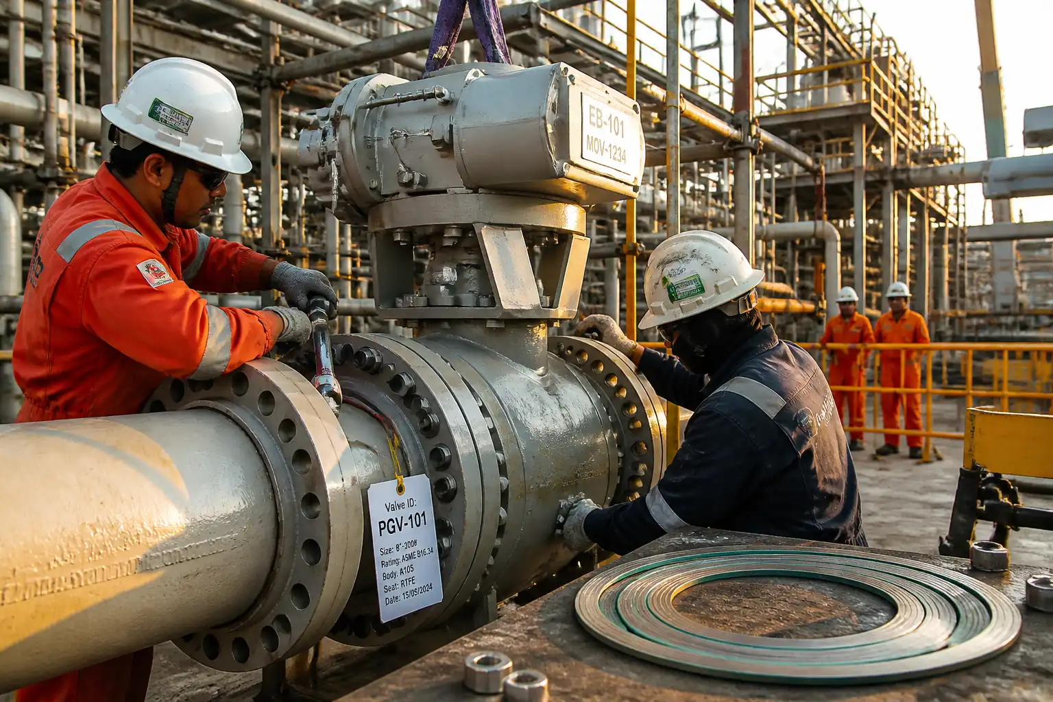
- Lifting/handling using certified rigging; installation into pipework or skid; alignment; gasket fit-up; controlled bolting per ASME PCC-1.
- Actuator interface per ISO 5211, bracket/coupling alignment, limit/torque stop setting, instrument air/hydraulic/electrical hook-up (terminations/testing coordinated with discipline leads).
- Functional stroking and leak checks; coordination of line/system pressure testing (hydrostatic/pneumatic) and valve seat/shell tests where specified.
- Marking/tagging, nameplates, flow arrows, lock-out provisions.
- QA/QC inspections, hold/witness points, records, and turnover dossiers.
Exclusions (unless noted by project)
- Fabrication/welding of new pipe spools beyond supports/connection details indicated by IFC drawings.
- Full commissioning or Cause & Effect testing of SIS/ESD systems (to be managed by commissioning team).
- Inline calibration of control valves/positioners beyond functional stroking and range checks.
Constraints/Interfaces
- Adherence to vendor IOM and project specs takes precedence for special-service valves (cryogenic, HIPPS, double block & bleed, severe-service trim).
References
| Document Type | Reference / Number | Revision | Notes |
|---|---|---|---|
| Code | ASME B31.3 – Process Piping (or applicable code of construction) | Pressure testing scope and allowable stresses; test pressure determination [Verify per project]. | |
| Standard | ASME B16.34 – Valves – Flanged, Threaded, and Welding End | Pressure/temperature ratings, materials, testing references. | |
| Standard | ASME B16.5 – Pipe Flanges and Flanged Fittings | Flange facing types, dimensions, bolting. | |
| Standard | ASME B16.10 – Face-to-Face and End-to-End Dimensions of Valves | Dimensional check of installed valves. | |
| Standard | ASME B16.20 – Metallic Gaskets; ASME B16.21 – Nonmetallic Gaskets | Spiral-wound, RTJ, and soft gaskets selection/acceptance. | |
| Guideline | ASME PCC‑1 – Guidelines for Pressure Boundary Bolted Flange Joint Assembly | Bolt-up procedures, tightening sequences, and documentation. | |
| Standard | API 598 – Valve Inspection and Testing; ISO 5208 – Pressure Testing of Metallic Valves | Shell/seat test criteria; leakage rates; certification. | |
| Standard | API 6D – Pipeline and Piping Valves | Use where specified for line valves in pipeline service. | |
| Standard | ISO 5211 – Industrial Valves – Part-turn Actuator Attachments | Mounting dimensions for actuators/gearboxes. | |
| Standard | NACE MR0175/ISO 15156 – Materials for H2S in Oil & Gas Production | Material/trim compliance for sour service [Verify per datasheet]. | |
| Standard | MSS SP‑25 – Standard Marking System for Valves, Fittings, Flanges | Tagging and permanent marking. | |
| Standard | MSS SP‑55 – Visual Method for Evaluation of Surface Irregularities | Castings/forgings surface acceptance (no injurious defects). | |
| Standard | ISO 9001 – Quality Management Systems | Supplier quality system and calibration traceability. | |
| Standard | ISO 8573‑1 – Compressed air quality classes | Recommended Class 3.4.3 or better for instrument air [Verify]. | |
| Project | IFC P&IDs, Line List, Valve Datasheets, 3D Model/Isometrics, Electrical/Instrumentation Drawings, Project Specs | Governing documents for selection and installation details. |
Responsibilities
| Role | Responsibility | Name / Party |
|---|---|---|
| Project Manager | Contractor Project Manager | Contractor |
| Supervisor | Piping Construction Supervisor | Contractor |
| Rigging Supervisor | Rigging Supervisor / Appointed Person | Contractor |
| QC | QC Inspector / QA Lead | Contractor |
| HSE | HSE Lead / HSE Officer | Contractor |
| Technicians | Pipefitters/Bolting Technicians | Contractor |
| E&I/Commissioning | Instrumentation/Mechanical Technician; Commissioning Engineer | Contractor |
| Vendor Rep | Valve/Actuator Vendor Representative | Supplier |
| Client Rep | Client/Engineer Representative | Client |
Resources
| Resource Type | Description | Quantity | Remarks |
|---|---|---|---|
| Labor | Pipefitters | 4–8 [Verify per workfront] | |
| Labor | Technician (torque/tension) | 2 | |
| Labor | Riggers & Banksman | 2–4 | |
| Labor | QC Inspector | 1 | |
| Labor | HSE Officer | 1 | |
| Labor | Instrumentation Technician | 1–2 | |
| Labor | Commissioning Engineer | 1 |
Materials
| Material | Specification / Grade | Quantity | Remarks |
|---|---|---|---|
| Valves | ASME B16.34/API 6D | As per valve schedule | |
| Gasket | ASME B16.20/B16.21 | Per joints | |
| Stud A193 B7/A320 L7; Nut A194 2H/7L [Verify] | ASME B16.5 bolting; project spec | Per flange | |
| Preservatives | Vendor IOM | As needed | |
| Paint | ISO 12944 [Verify] | As needed | |
| Steel | ASTM A36/A572 [Verify] | As per IFC |
Equipment
| Equipment | Capacity / Type | Quantity | Inspection Required |
|---|---|---|---|
| Torque wrench | Up to required torque | 2–3 | |
| Tensioner | Per stud size | Set | |
| Flange tools | Set | ||
| Rigging | Per lift plan | As required | |
| Measuring | Set | ||
| Testing | To test pressure | As required | |
| Access | As required |
Prerequisites
- Approved IFC drawings, P&IDs, line list, valve schedule, datasheets, isometrics, and 3D model where applicable.
- Approved ITP and Method Statement; risk assessment/JSA completed; Permit to Work (PTW) including Lifting Plan, Work at Height, Pressure Test, and Hot Work permits as applicable [Verify per project HSE plan].
- Vendor IOM/manuals and preservation instructions available; certificates (API 598/ISO 5208 test, MTRs, COC) verified.
- Calibrated tools/gauges available with valid certificates; bolting equipment set with target torque/tension calculations prepared.
- Access/Scaffolding erected and tagged; lighting as required.
- Utilities available: instrument air (ISO 8573-1 Class 3.4.3 or better [Verify]), hydraulic power unit/electrical as needed.
- Isolation and system status confirmed: spools depressurized, drained, cleaned, and blinded as needed; lock-out/tag-out (LOTO) in place.
- Materials inspected and accepted by QC (MIR closed). End caps intact; internal cleanliness verified (borescope where specified).
- Supports verified per drawings; any design changes issued via approved MOC.
- Coordination with commissioning for actuator settings and stroke/loop checks; client notified for hold/witness points.
- Environmental plan for testing media disposal (hydrotest water, nitrogen venting) approved.
Method Sequence
| Step | Activity | Description | Responsibility | Inspection / Hold Point |
|---|---|---|---|---|
| 1 | Pre-start briefing & PTW | Conduct toolbox talk covering lifting, bolting, pressure testing, and preservation. Confirm PTW, JSA, and permits in force. Establish exclusion zones and barricades. | Supervisor / HSE | Review JSA & PTW |
| 2 | Receiving inspection | Verify valve against PO/datasheet: type, size, class, materials, trim, end connection, NACE compliance where applicable. Check MSS SP-55 visual quality of bodies/bonnets, flange faces undamaged, RTJ grooves clean. Verify certificates (API 598/ISO 5208, MTRs). | QC / Storekeeper | Dimensional & visual |
| 3 | Preservation & storage | Fit/maintain end caps; apply vendor-approved VCI/oil if specified; add desiccants for long-term storage. Store indoors or covered, off the ground, temp 5–40°C, RH < 75% [Verify]. Rotate shafts quarterly; log preservation. | Storekeeper / QC | Periodic check |
| 4 | Pre-install verification | Confirm correct tag/line number, orientation (flow arrow), face-to-face (ASME B16.10), stem orientation (prefer stem vertical or horizontal-up; avoid downward in dirty service [Verify vendor IOM]). Verify support needs for heavy valves (>25 kg or per stress report) and thermal movement allowances. | Supervisor / QC | Check against P&ID/isometric |
| 5 | Prepare supports | Install or adjust pipe shoes/hangers/guides. For new welded supports, use approved WPS/WPQ per ASME IX; align to allow valve weight without overstressing pipe; allow thermal expansion (guided/sliding). | Pipefitter / Welder / QC | Fit-up and weld visual |
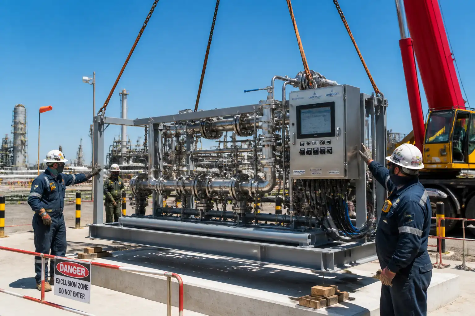
| 6 | Rigging & lift-in | Apply soft slings/spreader to body lifting lugs; protect flange faces. Maintain center-of-gravity control. No lifting via handwheels/actuators. Position valve between flanges/spool. | Rigging Supervisor / Riggers | Lift plan execution |
| 7 | Flange inspection & alignment | Clean flange faces and RTJ grooves. Check for dents/scratches beyond acceptance; lap only if approved. Align flanges: concentricity and parallelism using alignment pins/feeler gauges. | Pipefitter / QC | Face/bolt-hole check |
| 8 | Gasket selection & placement | Confirm gasket type/class and material per spec (e.g., Spiral-wound SS316/Graphite or RTJ ring). Ensure new, clean, undamaged. Insert gasket centered; for RTJ, correct profile and ring number. | Pipefitter / QC | Gasket verification |
| 9 | Studs/nuts installation | Verify stud length (2–3 threads protrusion beyond nut), grade, heat number. Clean/lubricate threads and nut bearing surfaces with approved compound. Install hardened washers if specified. | Bolting Tech / QC | Visual & ID check |
| 10 | Controlled bolt-up (torque/tension) | Tighten in at least three passes (cross/star pattern): 30%–60%–100% of target; final rotational pass clockwise. Determine target from bolt load (typically 45–60% of bolt proof load) using T = K·D·F with K per lubricant data [Verify per PCC‑1/project]. Mark bolts after final pass. | Bolting Tech / QC | Witness torque |
| 11 | Actuator mounting & interface | Verify ISO 5211 pattern; install bracket/coupling without side loads. Set mechanical stops. Align stem/coupling; run-out ≤ 0.5 mm TIR [Verify vendor]. Secure fasteners to specified torque with thread-locker if required. | Mech/Instrumentation Tech / Vendor Rep | Alignment check |
| 12 | Utilities hookup | Connect instrument air/hydraulic lines and electrical per drawings. Verify air quality class and supply pressure (e.g., 5.5–7.0 bar g for pneumatics [Verify]). Perform leak check (soap solution). Ensure hazardous area-rated equipment installed per zone/classification. | Instrumentation Tech / Supervisor | Leak/pressure check |
| 13 | Functional stroke check | Stroke valve min. 3 full cycles; verify open/close positions, travel time, limit switches/position feedback. For control valves, run 0–25–50–75–100% sweep and characterize as required. | Commissioning / Instrumentation / Vendor Rep | Functional test |
| 14 | Seat/shell test (if specified) | If project requires in-situ test beyond mill certs, isolate and test per API 598/ISO 5208. Pneumatic seat test with dry nitrogen (e.g., 6 bar g [Verify]) or hydrotest at specified differential. Use calibrated gauges; hold time per standard. | QC / Commissioning / Client | Pressure test |
| 15 | System pressure test coordination | Where line hydrotest is planned (ASME B31.3): confirm test boundaries, blinds, and valve test position (typically partially open or as specified). Protect actuators/positioners per vendor guidance. Drain/dry post-test. | Construction / QC / Commissioning | Boundary check |
| 16 | Restoration & cleanliness | Remove blinds/spools as planned; reinstall gaskets and re-bolt to spec. Clean valve externals; ensure internals free of debris. Reinstate preservation if not commissioned within 30 days [Verify]. | Supervisor / QC | Final check |
| 17 | Coating touch-up & insulation interface | Repair coating damage; verify DFT; mask stem/actuator. Reinstall insulation ensuring removable boxes around actuators/handwheels as specified. | Painting Crew / Insulation Crew | DFT/visual |
| 18 | Tagging & marking | Install permanent tag with valve number; verify MSS SP‑25 markings; apply flow arrow; install lockout hasp if required. | Supervisor / QC | Visual |
| 19 | Final QC & client walkthrough | Close punch items; verify documentation completeness; perform joint walkdown with client/engineer. | QC / Client Rep | Final IR |
| 20 | Handover records | Compile turnover dossier: certificates, bolt-up sheets, stroke/loop tests, preservation logs, as-builts, photos, permits, NCR closures. | QA Lead | Document review |
Health, Safety and Environment (HSE) – Safety Controls
Task-specific Hazards and Controls
1) Hazard: Lifting/rigging heavy valves
- Likely consequence: Crush injuries, dropped objects, equipment strike
- Engineering/procedural control: Engineered lifting plan; use certified slings/shackles/spreader bars; lift from OEM lugs; tag lines; establish exclusion zone; banksman control; pre-lift meeting.
- Required PPE: Hard hat with chin strap, gloves (cut-resistant), safety boots, eye protection, high-vis vest.
- Collective preventive measure: Barricades and spotters; load testing/certification tracking; proper storage of rigging.
- Inspection/permit/supervision: Approved lifting plan and PTW; daily rigging inspection; appointed person/banksman supervision [Verify per project HSE plan and local regulations].
2) Hazard: Pressurization during pneumatic/hydro tests
- Likely consequence: Component failure, projectile hazards, hearing damage
- Engineering/procedural control: Pressure test procedure; calibrated gauges; creep up pressure in increments; barricade test area; remote pressurization; use pressure relief; keep personnel out of line-of-fire.
- PPE: Face shield, hearing protection, gloves, safety boots.
- Collective measure: Physical barriers and signage; test boundary locks/keys control.
- Inspection/permit/supervision: Pressure test permit; QC witness; client hold point; supervisor present; emergency depressurization plan.
3) Hazard: Stored energy in spring-return actuators
- Likely consequence: Sudden movement causing pinching/impact
- Control: Follow OEM isolation; lock mechanical stops; depressurize; remove energy sources before mounting/coupling.
- PPE: Gloves, eye protection.
- Collective measure: LOTO procedures with tags; barriers during stroking tests.
- Inspection/permit/supervision: LOTO verification; permit to work; supervisor sign-off.
4) Hazard: Working at height (elevated valves)
- Likely consequence: Falls, dropped tools
- Control: Use certified scaffolds/MEWP; 100% tie-off where required; tool lanyards; proper access/egress.
- PPE: Full body harness, lanyard with shock absorber, helmet with chin strap.
- Collective measure: Guardrails, toe boards, netting.
- Inspection/permit/supervision: Scafftag/MEWP inspection; Work at Height permit; competent person supervision.
5) Hazard: Pinch points and hand injuries during bolting
- Likely consequence: Finger crush/cuts
- Control: Use flange spreaders/alignment pins; keep hands clear during torqueing; use impact guards; two-person communication.
- PPE: Impact-resistant gloves, eye protection.
- Collective measure: Exclusion zone; task sequencing to avoid simultaneous operations.
- Inspection/permit/supervision: Toolbox talk; supervisor monitoring.
6) Hazard: Hot work for support welding
- Likely consequence: Burns, fire, fumes
- Control: Hot Work Permit; fire watch; gas testing where required; fire blankets/screens; spark containment.
- PPE: Welding helmet, FR clothing, gloves, respirator as needed.
- Collective measure: Fire extinguishers, spark arresters, ventilation.
- Inspection/permit/supervision: Hot Work permit; gas test certificate; fire watch log; qualified welder.
7) Hazard: Nitrogen use for testing/actuators
- Likely consequence: Asphyxiation in poorly ventilated areas
- Control: Use in open/ventilated areas; monitor oxygen where enclosed; secure cylinders; regulator/flashback arrestors as specified.
- PPE: Eye protection, gloves, safety boots.
- Collective measure: Ventilation; barricades around vent points.
- Inspection/permit/supervision: Gas testing where required; cylinder inspection; supervisor sign-off.
8) Hazard: Electrical hazards from actuators/cabling
- Likely consequence: Shock, arc flash
- Control: Isolate circuits; test-before-touch; correct EEx rating; use competent electrician.
- PPE: Insulated gloves, eye protection; arc-rated PPE where required.
- Collective measure: Lockable isolators; barriers.
- Inspection/permit/supervision: Electrical permit; inspection of terminations; continuity/IR tests recorded.
9) Hazard: Chemical exposure (lubricants/solvents/paints)
- Likely consequence: Dermatitis, respiratory irritation
- Control: Use OEM-approved chemicals; follow SDS; use minimal quantity; provide ventilation.
- PPE: Nitrile gloves, goggles, half-mask respirator with appropriate cartridges when required.
- Collective measure: Spill kits; bunded storage.
- Inspection/permit/supervision: SDS available; COSHH/chemical permit where applicable.
10) Hazard: Confined/limited access around pipe racks
- Likely consequence: Strain injuries, entrapment
- Control: Good housekeeping; planned access routes; staged materials; mechanical aids for positioning.
- PPE: Standard site PPE.
- Collective measure: Access platforms.
- Inspection/permit/supervision: Supervisor checks; ergonomics briefing.
Environmental Controls
- Potential spill from lubricants/preservatives: Use drip trays and absorbents; store in bunded areas; dispose per waste streams. Record any spills and clean immediately.
- Hydrotest water discharge: Analyze/test as required; neutralize inhibitors; discharge to approved drains with permits; use filtration/sediment bags where needed [Verify per project environmental plan].
- Nitrogen venting: Vent to safe area downwind; control noise with mufflers; asphyxiation controls as in HSE section.
- Waste segregation: Collect used gaskets, damaged studs/nuts, and packaging separately; dispose/recycle per site waste management plan.
- Coating overspray/DFT checks: Mask adjacent equipment; contain overspray; collect contaminated wipes/filters as hazardous waste where applicable.
- Noise/vibration: Schedule high-noise activities; use acoustic barriers; hearing protection program.
- Dust/debris: Keep flange faces protected; use lint-free wipes; no wire-brushing RTJ grooves that may shed contaminants into system.
- Energy efficiency: Shut down idling equipment; use electric torque tools where feasible.
Quality Assurance / Quality Control
- ITP implementation with defined Hold (H), Witness (W), Surveillance (S) points for receiving, fit-up, bolt-up, actuator fit, stroke tests, and pressure tests.
- Material traceability: Verify valve body/trim materials, NACE compliance where applicable, gasket/bolting grades; retain MTRs/COCs.
- Dimensional checks: Face-to-face per ASME B16.10; flange compatibility per ASME B16.5; orientation/flow direction per datasheet.
- Flange joint integrity: Execute per ASME PCC-1; compute torque/tension targets; document passes; verify protrusion (2–3 threads), lubrication used, and final rotational pass.
- Instrument/actuator QA: Verify ISO 5211 interface, coupling fit, stop settings, feedback calibration, stroking cycles, and fail position; record stroke time and position accuracy (typ. ±2% or per vendor) [Verify].
- Testing: Accept valve factory certifications (API 598/ISO 5208) unless project requires in-situ tests; if testing, use calibrated gauges; define leakage class (e.g., ISO 5208 Rate A/B soft seat; Rate D metal) [Verify].
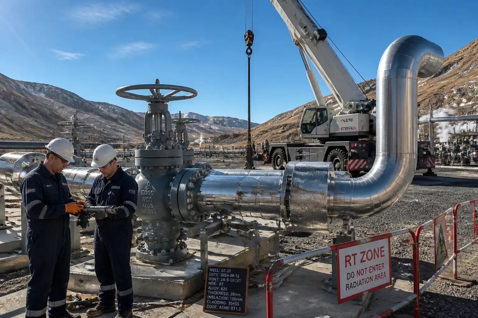
- Support verification: Confirm supports installed per drawings; welded supports to approved WPS/WPQ; NDE as per project.
- Coating QA: Touch-up per spec; DFT verified with calibrated gauge; color code/ID maintained.
- Documentation: IRs, MIRs, RFIs, bolt-up worksheets, test certificates, calibration certs, preservation logs, photos before/after installation. NCR raised for nonconformities; corrective action verified.
- Turnover: Compile signed checklists, ITRs, as-builts, redlines, and vendor reports into system turnover packages aligned with system/subsystem breakdown.
Attachments
- IFC P&IDs, isometrics, valve schedule, and line list
- Valve/actuator vendor IOMs and data sheets
- Approved Lifting Plans and Rigging Studies
- Bolting calculations and torque/tension tables (ASME PCC‑1 basis)
- Calibration certificates (torque tools, pressure gauges, DFT meters)
- WPS/PQR/WPQ for support welding; NDE reports
- Pressure test procedures and approved test packs
- HSE documents: PTW, JSA, SDS for lubricants/solvents/paints
- Preservation procedures and logs
- Inspection Reports (IR), Material Inspection Reports (MIR), RFIs, NCRs
- As-built redlines and photo records
This content is a read-only public reference. Download or customize to get an editable version.
ITP preview
The first inspection activities from the linked ITP for Method Statement: Oil & Gas Valve Installation and Testing:
| Activity | Inspection / Test | Acceptance Criteria | Responsibility | Record |
|---|---|---|---|---|
| Receiving inspection | Visual/dimensional; cert review | Matches datasheet/P&ID; markings per MSS SP‑25; no injurious defects (MSS SP‑55). | QC / Client (W/H) | MIR; IR; photo log |
| Storage/preservation check | Visual/internal cleanliness | End caps fitted; no corrosion/ingress; preservation log current. | QC | Preservation log; IR |
| Pre-install verification | Document check; visual | Correct valve tag/line; orientation; F-F per ASME B16.10; supports identified. | QC / Supervisor | Checklist; RFI (if client W) |
Showing 3 of 14 inspection activities. View full ITP →
Related Inspection and Test Plan
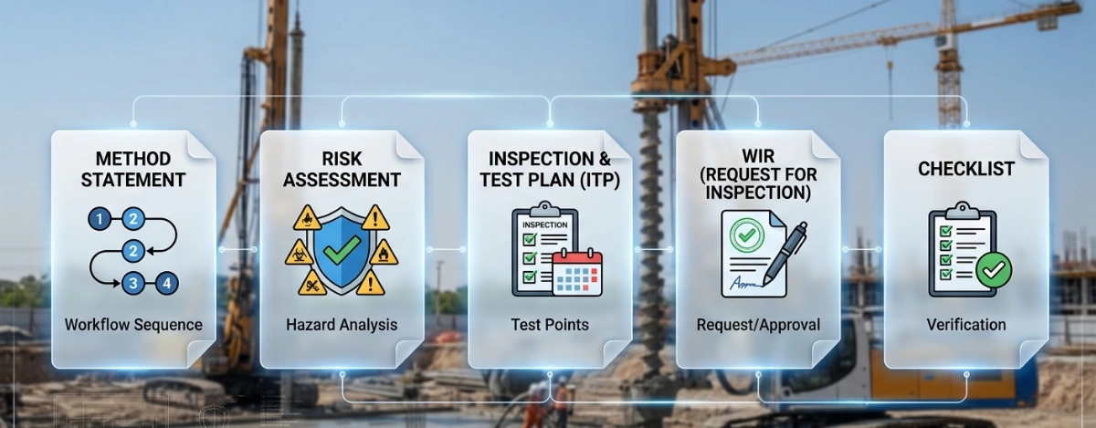
An Inspection and Test Plan (ITP) is available for Method Statement: Oil & Gas Valve Installation and Testing. The ITP defines the inspection activities, acceptance criteria, hold and witness points, responsible parties, and records required to verify the work described in this method statement.
View the Method Statement: Oil & Gas Valve Installation and Testing ITP →Frequently asked questions
Continue with related Quollnet resources connected to this method statement.