
Method Statement: Geothermal Production Wellhead Equipment and Piping Installation – Method Statement
AI-assisted method statement with matching ITP, PDF download, and Excel export.
More than a static template
Unlike a downloadable Word or PDF template, this method statement is an AI-assisted editable starting point connected directly to a matching Inspection and Test Plan. Every section is structured, project-adaptable, and ready to export.
- AI-assisted drafting — Customize every section with AI for your specific project scope.
- Linked ITP — A matching inspection and test plan is generated alongside the method statement.
- Multiple export formats — Download as a formatted PDF or editable Excel spreadsheet.
- Editable starting point, not a final document — Review, verify, and adjust all content against your project requirements before use.
Static template vs. Quollnet workflow
| Feature | Static template | Quollnet |
|---|---|---|
| Project-specific content | Manual fill-in required | AI-assisted customization |
| Linked ITP | Separate document, no link | Matching ITP included |
| Export formats | Usually PDF only | PDF and Excel |
| Structured sections | Free-form layout | 13 standardized sections |
| Saved to your account | Local file only | Cloud-saved, reusable |
| Content accuracy | You verify everything | AI-assisted, you still verify |
| Cost | Often free but time-intensive | Free to customize and download |
What you can customize
When you save this method statement to your account, every section becomes editable. The following 13 sections are included:
- Scope — Defines the activity and its boundaries.
- References — Standards, specifications, and drawings.
- Responsibilities — Roles and accountabilities.
- Resources — Labour, plant, and equipment summary.
- Materials — Materials and compliance requirements.
- Equipment — Tools and equipment details.
- Prerequisites — Hold points and pre-conditions.
- Method sequence — Step-by-step construction sequence.
- Safety controls — HSE risk controls and PPE.
- Environmental controls — Environmental mitigation measures.
- QA/QC — Quality inspection and test requirements.
- ITP — Inspection and Test Plan table (has its own page).
- Attachments — Referenced drawings and documentation.
Why this method statement is used
This method statement is used to define and communicate the approved procedure for carrying out method statement: geothermal production wellhead equipment and piping installation on site. It ensures the work is planned in advance, the correct resources and controls are in place, and all personnel understand responsibilities, sequence, quality requirements, and safety controls before work begins. It aligns site execution with the documented scope and acceptance expectations.
Who uses this method statement
This method statement is used by contractors, site supervisors, project engineers, QA/QC engineers, HSE officers, consultants, and client representatives. It serves as a shared reference for planning, execution, supervision, inspection, and approval of the activity on site.
When it is prepared and submitted
The method statement is prepared before the work activity starts and submitted as part of the pre-construction documentation package for review and approval.
Who reviews or approves it
The method statement is usually submitted to the client representative, consultant, resident engineer, or project management consultant for review and approval before the work commences.
Important approval note
This method statement is an AI-assisted editable starting point, not a pre-approved document. Before use on any project, all content must be reviewed and approved by the relevant parties (superintendent, principal contractor, or client representative) in accordance with your contract and project quality plan.
For example: if your specification requires a departure from a referenced standard, that departure must be documented and approved separately — this method statement will not capture that automatically. Always verify against your applicable drawings, specifications, and regulatory requirements.
Method statement content
Scope
Work Summary
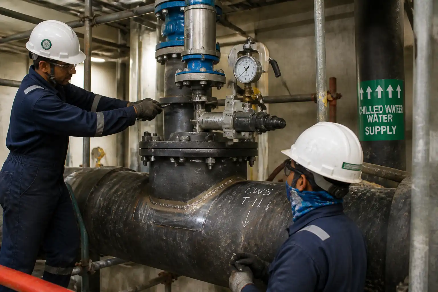
This method statement covers the contract execution requirements to install and commission geothermal production wellhead equipment and associated high-temperature piping. Major elements include:
- Receiving, inspection, and installation of API 6A wellhead/Christmas tree components, including master valve assembly
- Installation of high-temperature alloy gate/globe/stop-check valves and fittings
- Fabrication and erection of geothermal production piping, including expansion loops and supports
- High-integrity bolting, gasket installation, torque/tensioning
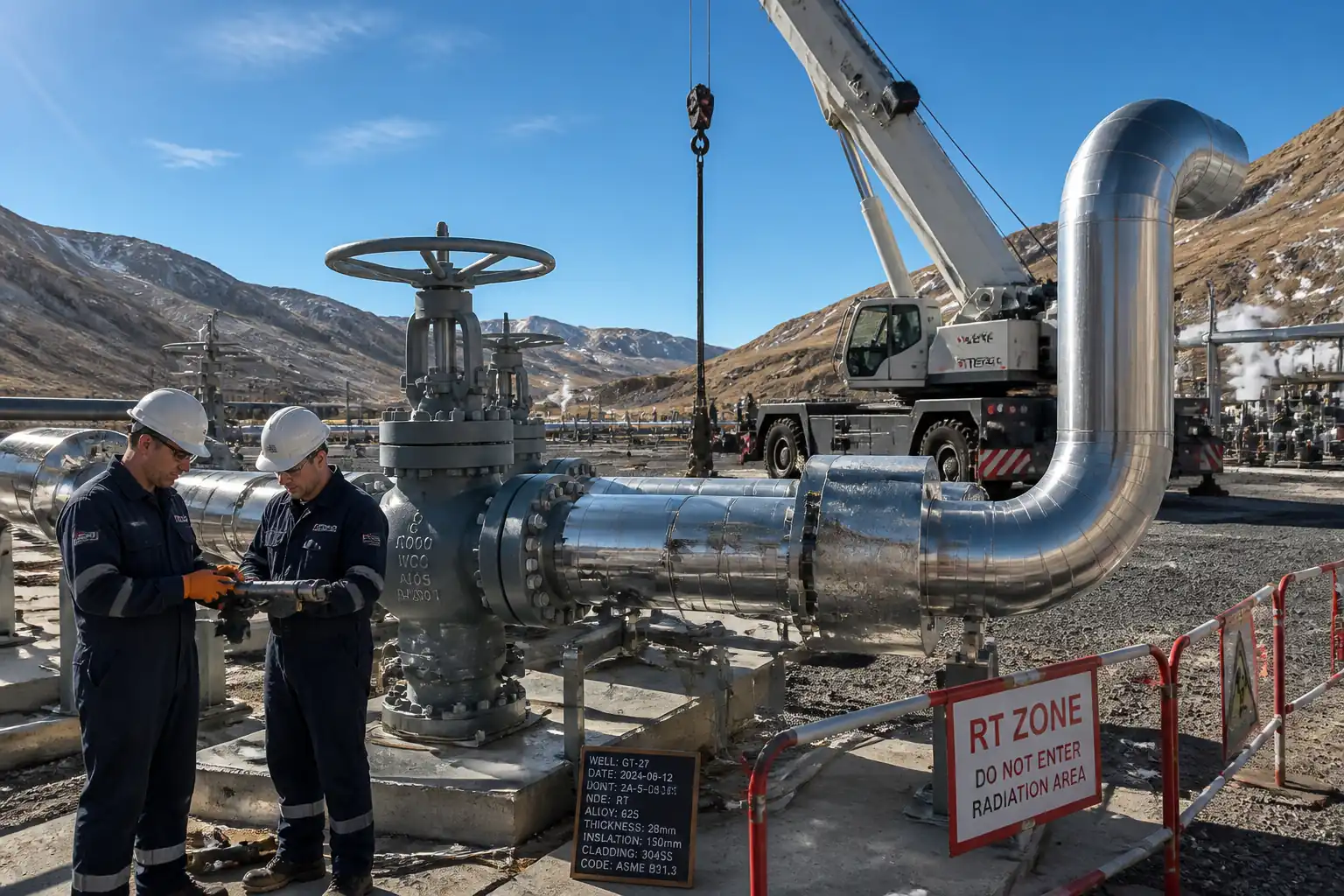
- Welding and NDE, including 100% radiographic examination of designated butt welds [Verify per project specifications]
- Pressure testing of piping systems per ASME B31.3 [Verify per project specifications]
- Thermal insulation and cladding of hot lines and equipment
- Functional testing, punch list clearance, and turnover documentation
Exclusions
- Drilling operations and subsurface completion
- Civil foundation construction beyond verification for equipment setting
- Process control system programming and DCS integration beyond loop functional checks
Deliverables
- Approved ITP with hold/witness points
- As-built drawings, weld maps, and NDE dossiers
- Hydrotest packs and reinstatement certificates
- Material traceability dossiers (MTCs, PMI)
- Torque/tensioning records and flange management reports
- Insulation data sheets and inspection reports
- HSE records (permits to work, lift plans, radiation safety logs)
Key Performance Criteria
- Leak-free startup at cold and hot conditions
- Dimensional tolerances met for alignment and support settings
- Compliance with welding/NDE acceptance criteria per code
- Proper accommodation of thermal growth without overstress
- All documentation complete and approved by Client
[All values marked "Verify per project specifications" shall be confirmed prior to works.]
References
| Document Type | Reference / Number | Revision | Notes |
|---|---|---|---|
| Standard | API 6A | Valve/equipment certification and pressure/temperature rating verification. | |
| Code | ASME B31.3 | Acceptance criteria for VT/RT, pressure test, materials and supports. | |
| Code | ASME BPVC Section IX | All welders and procedures to be qualified per alloy group/P-No. | |
| Code | ASME BPVC Section V | RT per Article 2; alternative ISO 17636-1/-2 permitted [Verify]. | |
| Standard | ASME B16.5 / API 6A | Flange facing, gasket types, pressure class compatibility [Verify]. | |
| Standard | ASME B16.20 | Gasket material compatibility with temperature and media. | |
| Standard | ASTM A193 / A194 | Grades B7/B16, A194 2H/7; verify temp limits and hardness. | |
| Standard | API RP 578 / ASTM E1476 | PMI extent for alloy materials; hardness control to prevent embrittlement. | |
| Standard | ASTM C533, ASTM C547, ASTM C411, ASTM C795, ASTM B209/A240 | Calcium silicate/mineral wool, hot-surface performance, CUI mitigation, aluminum/stainless cladding. | |
| Standard | ASME B30.5 / B30.9 | Lifting plans, rigging hardware, inspections. | |
| Standard | ISO 12944 / SSPC-SP | Surface prep grade and high-temp coating system [Verify]. |
Responsibilities
| Role | Responsibility | Name / Party |
|---|---|---|
| PM | Ensures approvals and resources | Contractor |
| CM | Implements method and schedule | Contractor |
| QA/QC | Approves ITP, WPS, NDE procedures | Contractor |
| WE | Ensures weldability and heat treatment controls | Contractor |
| LS | Controls lifting operations and communication | Contractor |
| NDE | Executes RT per code with radiation safety | Subcontractor |
| HSE | Implements task-specific controls | Contractor |
| Client | Approvals and verification | Client |
Resources
| Resource Type | Description | Quantity | Remarks |
|---|---|---|---|
| Personnel | Construction Manager, Site Engineers (2), Lifting Supervisor | 5 | |
| Personnel | Alloy piping and flange fit-up | 8 | |
| Personnel | GTAW/SMAW for high-temp alloys | 6 | |
| Personnel | RT Level II, film/digital | 3 | |
| Personnel | Insulators (4), Cladders (2) | 6 | |
| Personnel | Certified riggers and signallers | 4 |
Materials
| Material | Specification / Grade | Quantity | Remarks |
|---|---|---|---|
| As per drawings | |||
| As per MTO | |||
| As per MTO | |||
| As required | |||
| As required | |||
| As required | |||
| As per MTO | |||
| As per MTO |
Equipment
| Equipment | Capacity / Type | Quantity | Inspection Required |
|---|---|---|---|
| 50–80 t | 1 | Yes | |
| Up to 30,000 N·m | 2 sets | Yes | |
| 6 | Yes | ||
| 1 set | Yes | ||
| Up to [Verify] bar | 1 set | Yes | |
| 1 each | Yes | ||
| As required | Yes |
Prerequisites
- Approved IFC drawings, P&IDs, isometrics, support details, and expansion loop design calculations
- Approved Method Statement, ITP, WPS/PQR, NDE procedures, lift plans, and permits to work
- Material deliveries with MTCs; PMI plan approved; heat number mapping registers prepared
- Tools and instruments calibrated (torque tools, gauges, RT equipment, PMI, hardness)
- Foundation/skid elevation and anchor bolts surveyed and within tolerance: anchor bolt position ±3 mm, projection +10/−0 mm [Verify]
- Hazard assessment and task-specific JSA completed; emergency response plan for radiation and high-pressure testing in place [Verify per project HSE plan and local regulations]
- Area barricaded and access arranged; scaffolds/MEWPs inspected and tagged
- Isolation and lockout/tagout procedures agreed for existing live systems
- Weather and wind limits for lifting defined (e.g., wind speed ≤ 9 m/s for critical lift) [Verify]
- Pipe spools fabricated with dimensional tolerance: length ±3 mm, flange face parallelism ≤ 0.5 mm/100 mm, hi–lo ≤ 1.5 mm (butt joints) [Typical]
- Pre-test pack compiled: calibrated gauges, test boundaries, blinds, test fluid availability (deionized water, chloride ≤ 50 ppm for austenitic SS) [Verify]
Method Sequence
| Step | Activity | Description | Responsibility | Inspection / Hold Point |
|---|---|---|---|---|
| 1 | Material receipt and storage | Receive wellhead, valves, and alloy materials; verify MTCs; store on skids, protect machined faces with covers; segregate by heat numbers. | QC Inspector / Storekeeper | Incoming inspection |
| 2 | Foundation and anchor verification | Survey base elevations and anchor bolts; verify grout pads/plates level within ±2 mm per 1 m; clean bearing surfaces. | Site Engineer / Surveyor | Survey check |
| 3 | Pre-installation meeting | Review lift plan, PTW, sequence, hold points, and contingency; confirm all tools and spares (gaskets, studs) available. | Construction Manager | HSE/QA attendance |
| 4 | Lift and position wellhead master valve | Rig and lift per plan using spreader bar; align to studs/hub; set on gasket; avoid impact on sealing faces. | Lifting Supervisor / Riggers | Pre-lift inspection |
| 5 | Gasket installation | Confirm gasket type/size/class; clean faces with lint-free cloth; install new gasket only; apply anti-seize to studs if specified. | Pipefitter / QC | QC verification |
| 6 | Stud bolt installation and tightening | Install studs/nuts hand-tight; lubricate as specified; tighten in star pattern in 3–4 passes to specified torque/tension. | Pipefitter / Torque Technician | Witness torque |
| 7 | Valve function check | Cycle master valve fully open/close; verify position indicators; record operating torque/pressure for actuators if any. | Mechanical Supervisor | Function witness |
| 8 | Expansion loop spool fit-up | Offer-up prefabricated expansion loop; verify orientation, leg lengths, cold spring (if specified), and support locations. | Pipefitter / Site Engineer | Dimensional check |
| 9 | Pipe support installation | Install anchors, guides, springs/constant supports; set cold settings; lock-outs removed post-test per plan. | Pipe Support Crew | QC/Engineer check |
| 10 | Weld joint preparation | Bevel prep per WPS; clean to bright metal; confirm root gap 2–3 mm; hi–lo ≤ 1.5 mm; install purge dams for SS/Ni alloys. | Welder / Welding Inspector | Fit-up inspection |
| 11 | Preheat and welding | Apply preheat per WPS (e.g., 150–200°C for Cr-Mo; 50–100°C for high-strength SS) [Verify]; control interpass (e.g., ≤ 315°C for P5; ≤ 175°C for austenitic SS) [Verify]. GTAW root with inert purge; fill/cap per WPS. | Welder / Welding Engineer | In-process surveillance |
| 12 | Intermediate NDE | VT 100%; PT/MT of root or finished surface as specified for alloy/critical joints. | QC / NDE Tech | Hold point as ITP |
| 13 | Postweld heat treatment (if required) | PWHT per WPS/PQR and code; controlled thermal cycle with calibrated thermocouples; soak time per thickness. | Welding Engineer / Heat Treat Subcontractor | Witness setup |
| 14 | Radiographic testing (RT) | 100% RT on designated butt welds; technique per ASME V or ISO 17636; establish exclusion zone; film/digital IQI sensitivity ≤ 2% (wire 10–13). | NDE Level II/III | Hold/witness |
| 15 | Flange joint management before testing | Verify gasket compatibility, bolt load, and flange alignment; install blinds/test spades as per test limits. | QC / Pipefitter | Pre-test checklist |
| 16 | Pressure test (hydrostatic preferred) | Fill, vent, and pressurize system to test pressure per ASME B31.3: typically 1.5 × design pressure adjusted for allowable stress ratio [Verify]; hold ≥10 min strength, ≥30 min leak; temperature > 10°C and < 50°C. | Test Engineer | Hold/witness |
| 17 | Draining, drying, and reinstatement | Drain test water to approved facility; dry lines with oil-free air or nitrogen; reinstall blinds to service config; remove spring locks. | Mechanical Supervisor | Post-test inspection |
| 18 | Thermal insulation application | Verify dry, coated surfaces; apply insulation thickness per spec (e.g., 50–100 mm) [Verify]; stagger joints; secure with SS bands at ≤300 mm pitch on elbows. | Insulation Supervisor | In-process QA |
| 19 | Cladding installation | Install metal jacketing with overlaps (circumferential ≥ 50 mm; longitudinal ≥ 75 mm); expansion joints at 6–9 m or per design; sealants per spec. | Cladding Team | Visual |
| 20 | Hot alignment and hot torque (if specified) | After initial heat-up, verify supports travel; perform controlled hot torque on selected flanges per procedure. | Site Engineer / Torque Technician | Witness |
| 21 | System functional checks | Stroke test valves; verify bypasses, drains, and instrumentation impulse lines; confirm tagging and flow direction. | Mechanical/Commissioning Engineer | Witness |
| 22 | Final walkthrough and punch closure | Joint punch with Client; close actions; compile turnover dossier. | QA/QC Manager | Final inspection |
Safety Controls
Task-specific hazards and controls
1) Hazard: Heavy lifting of valves/wellhead components (crane operations)
- Likely consequence: Crushing, dropped load, rigging failure
- Engineering/procedural control: Engineered lift plan, certified crane/rigging, D/d ratio compliance, exclusion zone > 1.5 × load height, tagline control, wind limit ≤ 9 m/s [Verify]
- Required PPE: Helmet with chin strap, gloves, safety boots, eye protection, high-vis
- Collective preventive measure: Barriers and spotters; radio comms with dedicated banksman
- Inspection/permit/supervision: Pre-lift inspection, lift permit, Lifting Supervisor present
2) Hazard: Working at height on wellhead and piping
- Likely consequence: Fall from height
- Engineering/procedural control: Certified scaffold/MEWP, 100% tie-off to approved anchor, edge protection, tools tethered
- Required PPE: Full-body harness with double lanyard, helmet, non-slip boots
- Collective preventive measure: Guardrails and toe boards; fall arrest systems
- Inspection/permit/supervision: Scaffold tags (green), MEWP checks, Working at Height permit
3) Hazard: Hot work (welding, grinding)
- Likely consequence: Burns, fire, eye injury, fumes
- Engineering/procedural control: Hot work permit, fire watch, screens, fume extraction/local ventilation, fire-rated blankets
- Required PPE: FR clothing, welding helmet/face shield, heat-resistant gloves, respirator as required
- Collective preventive measure: Fire extinguishers and charged hose nearby; spark containment
- Inspection/permit/supervision: Hot work permit; continuous fire watch for 30 minutes post-work [Verify]
4) Hazard: Radiography (ionizing radiation)
- Likely consequence: Radiation exposure
- Engineering/procedural control: Controlled exclusion zone per calculation, barricades, warning beacons/signage, time–distance–shielding principles
- Required PPE: Personal dosimeter, alarming rate meter (RT crew)
- Collective preventive measure: Area evacuation and lockout, access control
- Inspection/permit/supervision: Radiation work permit; qualified Level II/III; regulatory licenses and source leak test certificates
5) Hazard: High-pressure testing
- Likely consequence: Hose whip, component rupture, projectile hazards
- Engineering/procedural control: Test boundary verification, test blinds rated ≥ test pressure, calibrated gauges, remote pressurization, barricaded zone
- Required PPE: Face shield, gloves, safety glasses, steel-toe boots
- Collective preventive measure: Exclusion zone, test shield/blankets, pressure relief valve
- Inspection/permit/supervision: Pressure test permit, checklist, competent Test Engineer oversight
6) Hazard: Exposure to geothermal gases/steam (H2S/CO2) during tie-ins
- Likely consequence: Toxic exposure, asphyxiation, burns
- Engineering/procedural control: Gas testing, continuous monitoring for H2S, positive isolation/LOTO, emergency shower/eyewash nearby
- Required PPE: H2S escape set, chemical goggles/face shield, heat-resistant gloves
- Collective preventive measure: Ventilation and controlled depressurization; muster points established
- Inspection/permit/supervision: Confined/controlled space entry permit if applicable; H2S training certificates
7) Hazard: Pinch points during flange alignment and torqueing
- Likely consequence: Hand injuries
- Engineering/procedural control: Flange spreading/alignment tools, hands-off tools, pinch-point awareness
- Required PPE: Cut-resistant gloves, eye protection
- Collective preventive measure: Job sequencing and clear communication
- Inspection/permit/supervision: Supervisor oversight; toolbox talks
8) Hazard: Insulation and cladding works (sharp edges, fiber dust)
- Likely consequence: Lacerations, respiratory/skin irritation
- Engineering/procedural control: Pre-cutting at ground, safe handling, dust suppression, vacuum extraction
- Required PPE: Cut-resistant gloves, long sleeves, safety glasses, P2/P3 respirator
- Collective preventive measure: Edge guards on cladding; housekeeping
- Inspection/permit/supervision: Task inspection; COSHH/SDS review
9) Hazard: Heat treatment/PWHT equipment
- Likely consequence: Burns, electrical shock
- Engineering/procedural control: Insulated mats, guarded heaters, lockable power supplies, temperature control interlocks
- Required PPE: Heat-resistant gloves, face shield, arc-rated clothing
- Collective preventive measure: Cordon off heated zone with thermal hazard signage
- Inspection/permit/supervision: Electrical inspection; permit for temporary power
[All measures to be verified per project HSE plan and local regulations].
Environmental Controls
- Hydrotest water management: Use clean water; cool before discharge; dechlorinate if necessary; route to approved containment; measure pH (6–9) and temperature (<35°C) prior to disposal [Verify]
- Potential NORM/scale: Geothermal scale may contain NORM or heavy metals; sample and classify; dispose via licensed facility if hazardous [Verify]
- Spill prevention: Drip trays beneath pumps and hydraulic tools; spill kits within 15 m; immediate cleanup and reporting
- Noise and vibration: Limit work hours near receptors; use acoustic blankets for RT generators/compressors where practicable; monitor per site plan
- Air emissions: Control welding fumes with local extraction; avoid Idling of plant; ensure generators meet emission standards
- Dust control: Cut insulation in controlled area; use HEPA vacuum; wet methods when feasible
- Waste segregation: Separate metal offcuts, gasket waste, insulation scraps; store mineral wool/calcium silicate dry; label hazardous waste
- Material protection: Keep alloy steel dry to prevent corrosion; protect insulation from rain prior to cladding
- Biodiversity/waterways: Maintain minimum 25 m buffer from watercourses for hydrotest and wash-down; deploy silt socks if required [Verify]
- Documentation: Maintain waste transfer notes, discharge permits, and environmental inspection checklists
QA/QC
Quality Assurance and Control Plan
- Document control: Use latest IFC drawings; redline as-built throughout; maintain weld maps linked to heat numbers
- Material traceability: 100% MTCs for pressure parts; PMI per approved plan focusing on alloy items, valves, flanges, and weld consumables
- Welder qualification: Valid per ASME IX for relevant P-No.; continuity maintained within 6 months [Verify]
- WPS/PQR: Qualified for base metal, thickness, position, heat input; purge details for stainless/nickel alloys; hardness limits where applicable
- Fit-up and alignment: Measured against code and WPS tolerances; use hi–lo gauges and calibrated tools
- NDE program: VT 100% of welds; RT extent per ITP (typically 100% for geothermal production butt welds) [Verify]; PT/MT where specified; acceptance per ASME B31.3
- PWHT: Per procedure with thermocouple locations recorded; calibrated charts retained in MDR
- Bolting QA: Calibrated torque tools; lubrication batch control; record torque/tension values and sequence
- Pressure testing: Test boundary drawings, calibrated gauges, vent/bleed points; chart recordings; acceptance per code
- Insulation/Cladding QA: Verify dry substrate, coating thickness (if specified), insulation thickness, proper overlaps, and weatherproofing details
- Nonconformance and corrective action: NCRs raised for deviations; corrective actions verified; re-inspection documented
- Handover: Complete MDR including ITP, WPS/PQR, welder logs, NDE, PWHT, PMI, hydrotest, torque sheets, coating/insulation reports, and as-built drawings
Attachments
- Marked-up P&IDs and isometric drawings with test limits
- Weld maps with line class and heat number traceability
- WPS/PQR register and welder qualification matrix
- NDE procedures and sample reports (RT technique sheets, IQI placement sketches)
- Lift plans and rigging studies for wellhead components
- Torque/tensioning procedures and flange management sheets
- Support schedules and spring hanger setting sheets
- Insulation details (spec sections, typical valve box details, expansion joint covers)
- Hydrotest procedure and sample test record with calculation of test pressure per ASME B31.3
- HSE permits: Hot Work, Radiography, Pressure Test, Working at Height, LOTO
- Manufacturer’s installation and O&M manuals for valves and wellhead equipment
This content is a read-only public reference. Download or customize to get an editable version.
ITP preview
The first inspection activities from the linked ITP for Method Statement: Geothermal Production Wellhead Equipment and Piping Installation:
| Activity | Inspection / Test | Acceptance Criteria | Responsibility | Record |
|---|---|---|---|---|
| Material receipt and PMI | Check MTCs, visual, PMI per plan | Materials match spec/grade/size; PMI within alloy range; documentation complete | QC Inspector / Client (W) | Receiving report, PMI log, MTCs |
| Foundation/anchor verification | Survey and level checks | Elevation and bolt positions within tolerance | Site Engineer / Client (W) | Survey report |
| Master valve installation | Face condition, gasket type, orientation | API 6A compatibility; correct gasket; no damage | QC Inspector / Client (H) | Inspection checklist |
Showing 3 of 12 inspection activities. View full ITP →
Related Inspection and Test Plan
An Inspection and Test Plan (ITP) is available for Method Statement: Geothermal Production Wellhead Equipment and Piping Installation. The ITP defines the inspection activities, acceptance criteria, hold and witness points, responsible parties, and records required to verify the work described in this method statement.
View the Method Statement: Geothermal Production Wellhead Equipment and Piping Installation ITP →Frequently asked questions
Continue with related Quollnet resources connected to this method statement.