Method Statement: Installation and Commissioning of Jockey Pump with Piping, Valves, and Pressure Switch Calibration – Method Statement
AI-assisted method statement with matching ITP, PDF download, and Excel export.
More than a static template
Unlike a downloadable Word or PDF template, this method statement is an AI-assisted editable starting point connected directly to a matching Inspection and Test Plan. Every section is structured, project-adaptable, and ready to export.
- AI-assisted drafting — Customize every section with AI for your specific project scope.
- Linked ITP — A matching inspection and test plan is generated alongside the method statement.
- Multiple export formats — Download as a formatted PDF or editable Excel spreadsheet.
- Editable starting point, not a final document — Review, verify, and adjust all content against your project requirements before use.
Static template vs. Quollnet workflow
| Feature | Static template | Quollnet |
|---|---|---|
| Project-specific content | Manual fill-in required | AI-assisted customization |
| Linked ITP | Separate document, no link | Matching ITP included |
| Export formats | Usually PDF only | PDF and Excel |
| Structured sections | Free-form layout | 13 standardized sections |
| Saved to your account | Local file only | Cloud-saved, reusable |
| Content accuracy | You verify everything | AI-assisted, you still verify |
| Cost | Often free but time-intensive | Free to customize and download |
What you can customize
When you save this method statement to your account, every section becomes editable. The following 13 sections are included:
- Scope — Defines the activity and its boundaries.
- References — Standards, specifications, and drawings.
- Responsibilities — Roles and accountabilities.
- Resources — Labour, plant, and equipment summary.
- Materials — Materials and compliance requirements.
- Equipment — Tools and equipment details.
- Prerequisites — Hold points and pre-conditions.
- Method sequence — Step-by-step construction sequence.
- Safety controls — HSE risk controls and PPE.
- Environmental controls — Environmental mitigation measures.
- QA/QC — Quality inspection and test requirements.
- ITP — Inspection and Test Plan table (has its own page).
- Attachments — Referenced drawings and documentation.
Why this method statement is used
This method statement is used to define and communicate the approved procedure for carrying out method statement: installation and commissioning of jockey pump with piping, valves, and pressure switch calibration on site. It ensures the work is planned in advance, the correct resources and controls are in place, and all personnel understand responsibilities, sequence, quality requirements, and safety controls before work begins. It aligns site execution with the documented scope and acceptance expectations.
Who uses this method statement
This method statement is used by contractors, site supervisors, project engineers, QA/QC engineers, HSE officers, consultants, and client representatives. It serves as a shared reference for planning, execution, supervision, inspection, and approval of the activity on site.
When it is prepared and submitted
The method statement is prepared before the work activity starts and submitted as part of the pre-construction documentation package for review and approval.
Who reviews or approves it
The method statement is usually submitted to the client representative, consultant, resident engineer, or project management consultant for review and approval before the work commences.
Important approval note
This method statement is an AI-assisted editable starting point, not a pre-approved document. Before use on any project, all content must be reviewed and approved by the relevant parties (superintendent, principal contractor, or client representative) in accordance with your contract and project quality plan.
For example: if your specification requires a departure from a referenced standard, that departure must be documented and approved separately — this method statement will not capture that automatically. Always verify against your applicable drawings, specifications, and regulatory requirements.
Method statement content
Scope
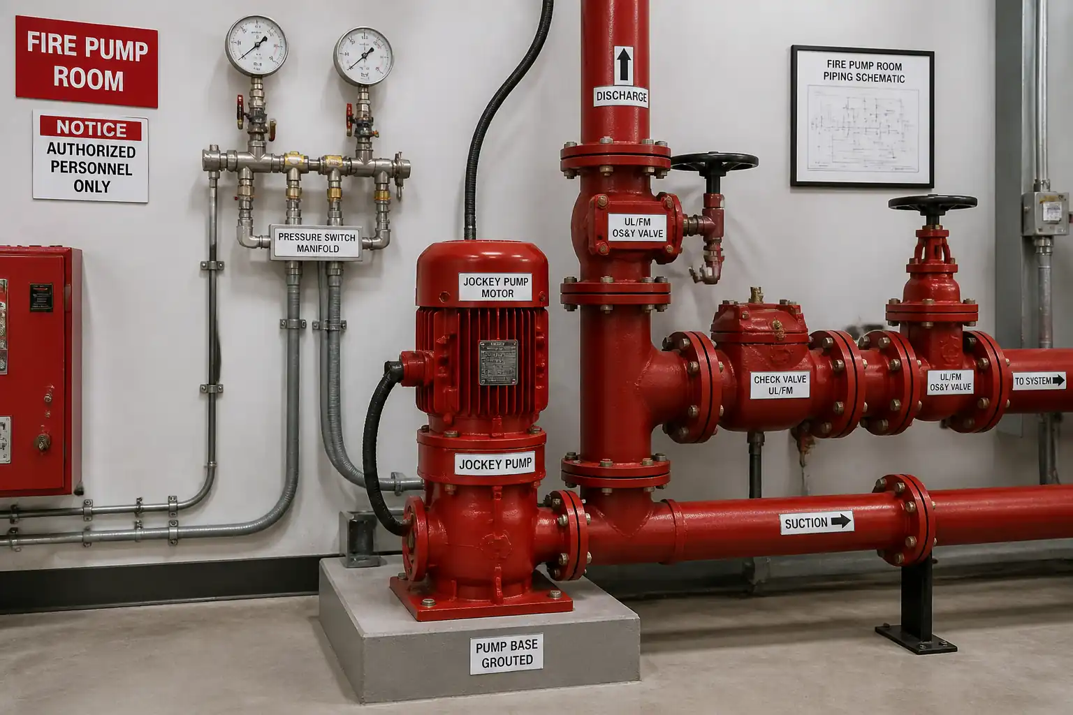
Work Summary
- Installation of jockey (pressure maintenance) pump set on housekeeping pad/baseplate including anchors and non-shrink grouting.
- Installation of suction and discharge piping spools, flexible connectors (if specified), check valve on discharge, isolation valves (OS&Y/butterfly) on suction and discharge, pressure gauges, pressure switch, and drains/vents.
- Electrical installation: termination to jockey pump controller/MCC, earthing/bonding, rotation check, functional interlocks per approved single-line diagrams.
- Hydrostatic pressure testing and flushing of connected sections as required by standards and project documents.
- Calibration of pressure switch cut-in/cut-out (HOLD POINT) with calibrated test gauge/manifold.
- Functional testing to verify auto start/stop, cut-in/cut-out pressures, absence of short cycling, and leak-free system.
- Documentation: inspection records, calibration sheets, test certificates, as-built redlines, O&M manuals for handover.
Exclusions/Interfaces
- Main fire pump installation/commissioning is by others but interface and setpoints must be coordinated to ensure jockey pump settings are above the main pump start and below relief limits [Verify per project specifications].
- BMS integration and remote monitoring points are covered by the controls contractor; terminations and I/O checks at the jockey pump controller interface form part of coordination.
Constraints and Considerations
- Maintain clearances required by manufacturer for maintenance access.
- Do not impose piping strain on the pump nozzles; align and support prior to final bolt-up.
- Pressure switch calibration is a formal HOLD point and must be witnessed by QA/QC and Client/Consultant as per ITP.
References
| Document Type | Reference / Number | Revision | Notes |
|---|---|---|---|
| Standard | NFPA 20 (latest adopted edition) | ||
| Standard | NFPA 13 (latest adopted edition) | ||
| Standard | NFPA 25 (latest adopted edition) | ||
| Standard | BS EN 12845 | Use where project specifies EN route; harmonize with NFPA if required [Verify per project specifications]. | |
| Standard | ASME B31.9 | ||
| Standard | MSS SP-58 / SP-69 | ||
| Standard | ASTM C1107 | ||
| Standard | NFPA 70 (NEC) / IEC 60364 | Select per project jurisdiction [Verify per project specifications]. | |
| Standard | EN 837-1 / ASME B40.100 | ||
| Standard | ISO/IEC 17025 |
Responsibilities
| Role | Responsibility | Name / Party |
|---|---|---|
| PM | Approve method/ITP, ensure procurement and manpower. | Contractor |
| CM/MEP | Supervise installation; verify interface readiness. | Contractor |
| QA/QC | Arrange hold/witness points; verify test instruments' calibration. | Contractor |
| HSE | Ensure HSE compliance and toolbox talks. | Contractor |
| Supervisor | Brief crew; verify method adherence. | Contractor |
| Electrician | Execute works per NEC/IEC; complete test sheets. | Contractor |
| Vendor Rep | Witness and sign off settings. | Supplier |
| Consultant | Review and approve settings and test outcomes. | Client/Consultant |
Resources
| Resource Type | Description | Quantity | Remarks |
|---|---|---|---|
| Labor | Install piping, valves, supports. | 2–4 | |
| Labor | Pump setting, alignment, grouting, coupling. | 2–3 | |
| Labor | Cabling, terminations, testing, rotation check. | 2–3 | |
| Staff | Permits, monitoring, toolbox talks. | 1 | |
| Staff | Inspections and ITP documentation. | 1 |
Materials
| Material | Specification / Grade | Quantity | Remarks |
|---|---|---|---|
| Pump | 1 set | ||
| Valve | 1 | ||
| Valve | 2–3 | ||
| Pipe/Fittings | As per BOQ | ||
| Flexible connector | As required | ||
| Grout | As required | ||
| Anchors | As required | ||
| Instrumentation | Per design |
Equipment
| Equipment | Capacity / Type | Quantity | Inspection Required |
|---|---|---|---|
| Chain block | ≥1 t | 1 | Yes |
| Level | 1 | Yes | |
| Alignment tool | 1 | Yes | |
| Torque wrench | 1–2 | Yes | |
| Test pump/manifold | Up to 20 bar / 300 psi | 1 | Yes |
| Test instruments | Set | Yes |
Prerequisites
- Approved shop drawings, vendor datasheets, material approvals, method statement, and ITP.
- Permits: Hot Work (if welding), Electrical LOTO, Pressure Testing, Confined Space (if applicable) [Verify per project HSE plan and local regulations].
- Housekeeping pad/base cast to correct elevation and dimensions; surface prepared and cured; anchors positioned per drawings or sleeves cast for post-installation.
- Calibrated instruments available: pressure gauges (class ≤1.0), alignment tools, torque wrench, electrical testers; calibration certificates valid (≤12 months) [Verify per project specifications].
- Utilities available: electrical supply, water for flushing/testing, drains identified for controlled discharge.
- Upstream/downstream system isolation confirmed; LOTO applied; system depressurized before any tie-in.
- Materials inspected and accepted; certificates and listings (UL/FM) verified.
- Access, lighting, housekeeping, and lifting arrangements prepared; lifting plan approved where required.
- Vendor/Manufacturer representative notified for commissioning support if required by warranty.
- Pre-commissioning checklists printed and briefed to the team.
Method Sequence
| Step | Activity | Description | Responsibility | Inspection / Hold Point |
|---|---|---|---|---|
| 1 | Receiving and Storage | Inspect jockey pump and accessories on delivery for damage, nameplate data, and UL/FM listings. Store indoors on skids, protected from moisture and dust. | Storekeeper / QA/QC | Material inspection |
| 2 | Base Preparation | Verify housekeeping pad levelness and dimensions. Position anchor bolts or drill and fix post-installed anchors as detailed. Dry fit base/frame and shim to achieve level within ±1 mm/m [Verify per project specifications]. | MEP Supervisor | Base check |
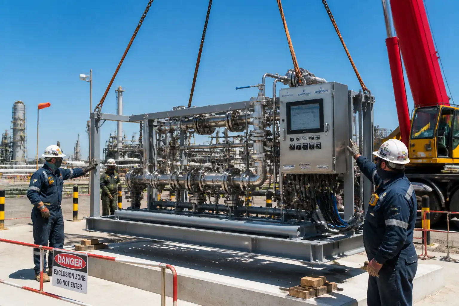
| 3 | Pump Positioning and Temporary Alignment | Lift pump/base with certified lifting gear; position on pad. Shim as required. For base-mounted sets, perform rough alignment of pump and motor; do not finalize until after grouting. | MEP Supervisor | Lifting supervision |
| 4 | Grouting of Base | Formwork/edge dams as needed. Mix and place non-shrink grout under baseplate continuously; avoid voids. Cure as per manufacturer. Do not torque anchors until grout reaches required strength (e.g., ≥70% in 24–48 h) [Verify]. | MEP Supervisor | Grout inspection |
| 5 | Final Alignment and Anchor Tightening | After grout cure, perform final pump/motor alignment using dial or laser per manufacturer tolerance (e.g., offset and angular misalignment within 0.05 mm TIR for small sets) [Verify]. Tighten anchor bolts to specified torque using calibrated torque wrench. | Mechanical Technician | Alignment check |
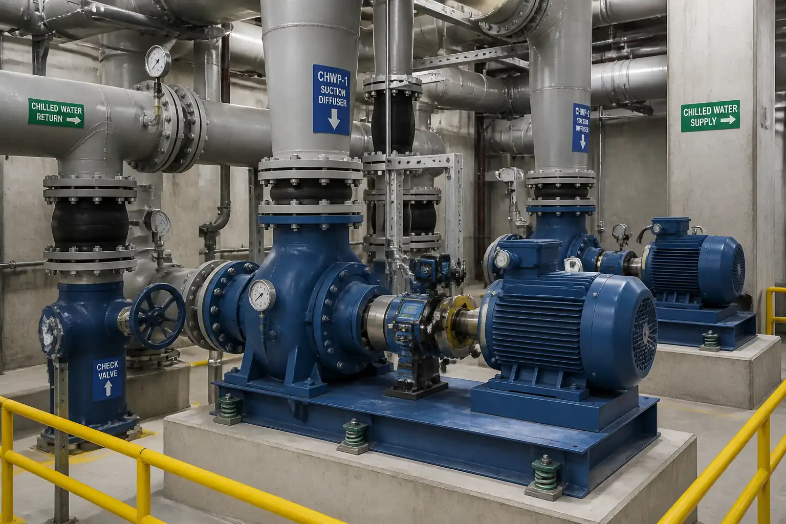
| 6 | Suction/Discharge Piping Installation | Install spools, flexible connectors (if specified), isolation valves (suction/discharge), and discharge check valve. Support piping independently before final nozzle connection (nozzle loads within OEM limits). Bolt-up with correct gasket and torque pattern. | Pipefitter | In-process inspection |
| 7 | Instrumentation Installation | Install pressure gauge(s) at discharge header and near pressure switch manifold. Install pressure switch with isolation valve, test tee, and bleed valve for calibration. Provide drain/vent points as detailed. | Pipefitter/Technician | Instrument check |
| 8 | Electrical Termination and Earthing | Install cables/conduits as per approved single-line and wiring diagrams. Terminate at jockey pump controller/MCC. Provide earthing/bonding. Verify overload/short-circuit protection and control logic per drawings. | Authorized Electrician | Electrical pre-check |
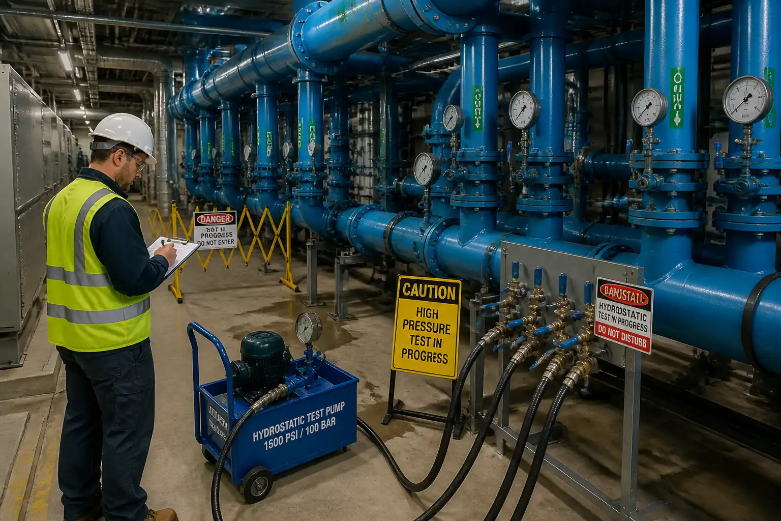
| 9 | Hydrostatic Testing (Local Sections) | Isolate and test new/modified piping sections. Pressurize to 200 psi (13.8 bar) or 50 psi (3.4 bar) above maximum system working pressure, whichever is greater, for 2 hours [Verify]. Monitor with calibrated gauge. | MEP Supervisor / QA/QC | Witness test |
| 10 | Flushing and Cleaning | Flush piping at required velocity per NFPA 13/BS EN 12845; discharge to approved drains with strainers. Ensure system free from debris before coupling to pump. | MEP Supervisor | Witness flush |
| 11 | Pre-Start Mechanical/Electrical Checks | Verify all fasteners torqued, guards in place, valves set (suction open, discharge open), vents primed, coupling guard fitted. Electrically verify LOTO status cleared, correct fuses/overloads, emergency stop functional. | Supervisor/Electrician | Checklist review |
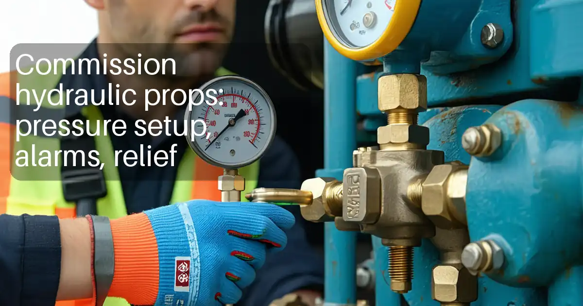
| 12 | Pressure Switch Calibration (HOLD POINT) | Isolate switch via test manifold. Using calibrated master gauge, adjust cut-in and cut-out setpoints: typical cut-in ≈ 10 psi (0.7 bar) below normal system pressure but ≥5 psi (0.35 bar) above main fire pump start; cut-out ≈ 10 psi (0.7 bar) above normal system pressure [Verify per project specifications]. Lock settings and apply tamper seal; label setpoints. | QA/QC + Vendor Rep | HOLD POINT – Client/Consultant witness |
| 13 | Initial Bump Test and Rotation Check | Jog motor to confirm correct rotation with coupling disengaged (if applicable). Correct phase if needed. Refit coupling/guard after confirmation. | Authorized Electrician | Witness |
| 14 | Functional Testing – Auto Start/Stop | With system pressurized to normal, slowly bleed pressure to trigger cut-in; observe auto start. Restore pressure to trigger cut-out; observe stop. Repeat thrice. Record pressures and times. | QA/QC + Supervisor | Witness test |
| 15 | Handover Documentation | Compile and submit records: material approvals, calibration sheets, hydrotest/flushing, alignment/torque, electrical tests, pressure switch certificate, functional test, as-builts, O&M manuals. | QA/QC Engineer | Document review |
Health, Safety, and Environment (HSE) – Safety Controls
Task-Specific Hazards and Controls
1) Hazard: Pressurized water release during testing or calibration
- Likely consequence: Injection injury, slips, equipment damage
- Engineering/procedural control: Install test manifold with isolation and bleed; depressurize before disconnecting; use rated hoses and fittings; set relief valve on test pump; barricade area and post signage
- Required PPE: Safety goggles/face shield, cut-resistant gloves, safety boots, long sleeves
- Collective preventive measure: Pressure testing permit; controlled discharge to drain; spill trays
- Inspection/permit/supervision: QA/QC to verify gauges and relief; Supervisor to enforce permit and LOTO; Consultant witness at hold point
2) Hazard: Electrical shock/arc during terminations and bump tests
- Likely consequence: Severe injury, burns, fatality
- Engineering/procedural control: LOTO for isolation; verify absence of voltage; use insulated tools; correct circuit protection; arc-flash boundaries [Verify per project HSE plan and local regulations]
- Required PPE: Electrically rated gloves, arc-rated face shield, arc-rated clothing, safety boots
- Collective preventive measure: Electrically competent persons only; barriers and signage; emergency stop tested
- Inspection/permit/supervision: Electrical work permit; Supervisor and HSE oversight; tool/tester calibration check
3) Hazard: Lifting and handling of pump/base and valves
- Likely consequence: Crush injuries, dropped loads
- Engineering/procedural control: Certified lifting gear and points; pre-lift meeting; taglines; keep clear of suspended loads
- Required PPE: Helmet with chin strap, gloves, safety boots, high-visibility vest
- Collective preventive measure: Exclusion zone; banksman/signaller control
- Inspection/permit/supervision: Lifting plan and inspection certificates; appointed person supervision
4) Hazard: Hot works (welding/brazing) if required for spools
- Likely consequence: Fire, fumes, burns
- Engineering/procedural control: Hot work permit; fire watch; fire blankets; ventilation; gas cylinder securing; gas leak checks
- Required PPE: Welding helmet, heat-resistant gloves, flame-resistant clothing, safety boots
- Collective preventive measure: Fire extinguishers and charged hose nearby; remove combustibles
- Inspection/permit/supervision: Hot work permit; fire watch for minimum 30 minutes post-work [Verify per project]
5) Hazard: Rotating equipment and pinch points at coupling
- Likely consequence: Lacerations, entanglement
- Engineering/procedural control: Guards installed before operation; no loose clothing; bump test with coupling uncoupled if required
- Required PPE: Safety glasses, gloves, fitted clothing
- Collective preventive measure: Interlocked/machine guarding where available; restricted access
- Inspection/permit/supervision: Pre-start checklist sign-off by Supervisor
6) Hazard: Chemical exposure from grout and cleaning agents
- Likely consequence: Skin/eye irritation, respiratory issues
- Engineering/procedural control: Follow SDS; wet curing methods; avoid dry mixing dust
- Required PPE: Chemical-resistant gloves, goggles, dust mask (P2/P3) as needed
- Collective preventive measure: Local ventilation; washing station
- Inspection/permit/supervision: SDS available on site; HSE inspections
7) Hazard: Confined or congested pump room work
- Likely consequence: Poor egress, heat stress, collision with plant
- Engineering/procedural control: Maintain clear escape routes; limit crew size; hydration plan; ventilation
- Required PPE: Helmet, gloves, boots
- Collective preventive measure: Housekeeping and floor marking; task zoning
- Inspection/permit/supervision: Supervisor walkdown; HSE monitoring of heat index
8) Hazard: Noise and vibration during functional tests
- Likely consequence: Hearing damage, hand-arm vibration
- Engineering/procedural control: Limit test duration; maintain equipment condition; distance where possible
- Required PPE: Hearing protection (earplugs/muffs)
- Collective preventive measure: Noise signage; scheduling to minimize exposure
- Inspection/permit/supervision: HSE to verify noise controls
9) Hazard: Inadvertent main fire pump start due to incorrect setpoints
- Likely consequence: Overpressure, system activation
- Engineering/procedural control: Coordinate setpoints; confirm main pump controller start pressure is below jockey cut-in by defined margin; isolate main pump during setting if permissible
- Required PPE: Standard PPE
- Collective preventive measure: Commissioning plan with interlocks and checks
- Inspection/permit/supervision: QA/QC and Consultant witness at calibration HOLD point
[All controls to be aligned with project HSE plan and local regulations.]
Environmental Controls
- Water discharge from flushing/testing: Route to approved drains with temporary hoses and strainers; prevent erosion and flooding; record discharge volumes if required by permit.
- Slurry and sediment: Capture debris with filter bags/strainers; dispose of solids as non-hazardous waste per local regulations.
- Chemical handling (grout/cleaners): Store in bunded area; avoid washout to drains; manage grout bags and contaminated PPE as construction waste.
- Noise: Schedule tests during permitted hours; use door closures; provide hearing protection and signage where levels exceed limits [Verify per local regulations].
- Waste management: Segregate metal offcuts, packaging, and general waste; recycle where facilities exist; maintain waste transfer notes.
- Energy use: Switch off lighting/tools when not in use; avoid idle running of test pumps.
- Spill prevention: Drip trays under pump during oil/grease application; spill kits available; report and log any spill.
- Indoor air quality: Provide ventilation during hot works or solvent use; maintain CO monitoring if combustion equipment is used [Verify per project HSE plan].
QA/QC
Inspection and Testing Requirements
- Instruments: Pressure gauges, torque wrenches, electrical testers to have valid calibration certificates (≤12 months) [Verify].
- Base Levelness: ±1 mm/m; record readings at four corners.
- Alignment: Within OEM limits; record dial/laser readings and temperature at time of measurement.
- Anchors: Torque to manufacturer values; record in torque sheet; chemical anchors pull-out tests if specified [Verify per project specifications].
- Piping: Verify support spacing per MSS SP-58 and drawings; ensure correct gasket type and bolt torque pattern.
- Hydrostatic Test: 200 psi (13.8 bar) or 50 psi above max working pressure (greater governs), hold 2 hours; no visible leakage or unacceptable pressure loss per NFPA 13/BS EN 12845 [Verify per project specifications].
- Electrical: Insulation resistance ≥2 MΩ at 500 VDC (motor power) and ≥1 MΩ (control circuits) unless OEM specifies otherwise [Verify]. Rotation correct; overload settings per motor FLA.
- Pressure Switch Calibration (HOLD): Cut-in/cut-out set to approved design values; tolerance ±2 psi (±0.14 bar). Apply tamper seal; label settings; record gauge serials and ambient conditions.
- Functional Test: Three successive auto start/stop cycles; no short cycling; current within nameplate; no abnormal noise/vibration; no leaks.
- Documentation: Maintain signed ITP checklists, calibration certificates, test reports, redlined drawings, and O&M manuals in the turnover dossier.
Acceptance
- All witness/hold points satisfied and signed by Client/Consultant.
- Deviations/NCRs closed with approved dispositions before handover.
Attachments
- Approved shop drawings (mechanical and electrical) for jockey pump installation and piping details.
- Manufacturer installation, operation, and maintenance (IOM) manuals.
- Material submittals and approvals (pump, valves, instruments, grout, anchors).
- Calibration certificates for gauges, torque wrenches, and electrical test instruments.
- Risk Assessment / Job Hazard Analysis (JHA) for this activity.
- Permits: Hot Work, Electrical LOTO, Pressure Testing, Confined Space (if applicable).
- Checklists: Base/Anchor, Piping Installation, Electrical Pre-Commissioning, Pre-Start, Functional Testing.
- ITP forms and sign-off sheets including HOLD/WITNESS point records.
- As-built redline markups of piping and instrumentation locations.
- Commissioning plan and start-up reports with vendor/consultant sign-offs.
This content is a read-only public reference. Download or customize to get an editable version.
ITP preview
The first inspection activities from the linked ITP for Method Statement: Installation and Commissioning of Jockey Pump with Piping, Valves, and Pressure Switch Calibration:
| Activity | Inspection / Test | Acceptance Criteria | Responsibility | Record |
|---|---|---|---|---|
| Materials receiving (pump, valves, instruments) | Verification of approvals, listings (UL/FM), certificates, and condition | Conforms to approved submittals; no damage; certificates available | QA/QC, Supplier Rep | Material Inspection Report |
| Base preparation and anchors | Level survey; anchor type/position check | Levelness ±1 mm/m; anchors per drawings/specs | QA/QC, MEP Supervisor | Base/Anchor Checklist |
| Grouting | Grout material compliance; placement and curing check | ASTM C1107 compliant; cure per manufacturer | QA/QC | Grout Inspection Report |
Showing 3 of 10 inspection activities. View full ITP →
Related Inspection and Test Plan
An Inspection and Test Plan (ITP) is available for Method Statement: Installation and Commissioning of Jockey Pump with Piping, Valves, and Pressure Switch Calibration. The ITP defines the inspection activities, acceptance criteria, hold and witness points, responsible parties, and records required to verify the work described in this method statement.
View the Method Statement: Installation and Commissioning of Jockey Pump with Piping, Valves, and Pressure Switch Calibration ITP →Frequently asked questions
Continue with related Quollnet resources connected to this method statement.