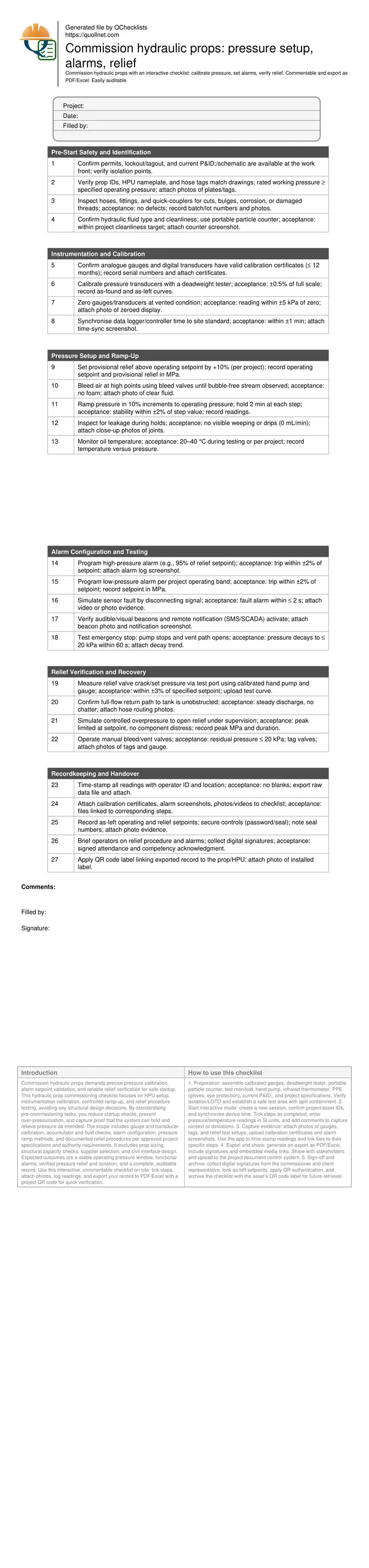
Commission hydraulic props: pressure setup, alarms, relief
Definition: Commission hydraulic props for construction and operations teams, focusing on pressure calibration, alarm configuration, logged readings, and relief verification, not structural design, to deliver safe startup and traceable performance.
- Calibrate set and operating pressures with certified gauges and logs.
- Configure and test alarms to protect equipment and workers.
- Record stable readings under load; capture time-stamped evidence and signatures.
- Interactive, commentable checklist with export and QR code verification.
Commission hydraulic props demands precise pressure calibration, alarm setpoint validation, and reliable relief verification for safe startup. This hydraulic prop commissioning checklist focuses on HPU setup, instrumentation calibration, controlled ramp-up, and relief procedure testing, avoiding any structural design decisions. By standardising pre-commissioning tasks, you reduce startup shocks, prevent over-pressurisation, and capture proof that the system can hold and relieve pressure as intended. The scope includes gauge and transducer calibration, accumulator and fluid checks, alarm configuration, pressure ramp methods, and documented relief procedures per approved project specifications and authority requirements. It excludes prop sizing, structural capacity checks, supplier selection, and civil interface design. Expected outcomes are a stable operating pressure window, functional alarms, verified pressure relief and isolation, and a complete, auditable record. Use this interactive, commentable checklist on site: tick steps, attach photos, log readings, and export your record to PDF/Excel with a project QR code for quick verification.
- Establishes a repeatable method to calibrate gauges and transducers, set operating and relief pressures, and validate alarms. Clear acceptance criteria and evidence prompts reduce rework, improve safety, and produce a defensible commissioning record suitable for audits and client turnover.
- Focuses on hydraulic performance only—pressure control, alarm behavior, and relief procedures—delivering a controlled ramp-up that avoids pressure shocks, protects seals and hoses, and confirms reliable depressurisation, without entering structural design or capacity calculations.
- Links measurements to people, place, and time. You capture serial numbers, calibration certificates, time-synchronised logs, and photos or videos. The result is a single source of truth that supports troubleshooting, warranty claims, and future maintenance planning.
- Interactive online checklist with tick, comment, and export features secured by QR code.
Pre-Start Safety and Identification
Instrumentation and Calibration
Pressure Setup and Ramp-Up
Alarm Configuration and Testing
Relief Verification and Recovery
Recordkeeping and Handover
Instrumentation calibration underpins reliable commissioning
Accurate instruments drive every decision when bringing hydraulic props online. Begin by confirming all gauges and transducers carry current calibration certificates and that their ranges suit expected pressures. Use a deadweight tester to verify linearity across the working range and to document as-found/as-left performance, then zero instruments with the circuit safely vented. Synchronise any data loggers or PLC clocks to site time so alarm events and pressure ramps align across records. Vent high points and test ports to remove entrained air that can distort readings or trigger false alarms. Place gauges at both the pump/manifold and near the prop to capture line losses during ramp-up. Only after instruments are trusted should you set provisional relief and start controlled pressurisation. These steps create defensible data, reduce misdiagnosis, and protect seals and hoses from unnecessary stress while you tune operating pressure and verify alarm behaviour.
- Use deadweight testing; target ±0.5% full-scale accuracy.
- Zero instruments; accept ±5 kPa at vented condition.
- Synchronise clocks to within one minute of site time.
- Position gauges to measure manifold and near-prop pressures.
- Purge air at high points before any ramp-up.
Controlled pressure ramp-up yields stable operation
With instruments validated, set a provisional relief above the intended operating pressure to provide a safety margin while avoiding nuisance lifts. Increase pressure in 10% increments, pausing at each step to observe stability, leaks, and temperature. Stability within a narrow band indicates sound hydraulic response; drift often points to air, bypassing, or temperature effects. Inspect all joints and hose interfaces under a bright light to catch weeping early. Maintain oil temperature within the band specified by the project so viscosity remains predictable. Document each hold with time-stamped readings at the manifold and near the prop to capture line loss; use these data to fine-tune the operating setpoint. A disciplined ramp-up reduces startup shock loads, prevents unexpected alarm trips, and proves the system’s ability to hold steady state before proceeding to relief and alarm verification testing.
- Ramp in 10% steps with 2-minute holds.
- Target stability within ±2% at each hold.
- No visible leaks; acceptable drip rate is zero.
- Keep oil temperature between 20–40 °C.
- Record manifold and near-prop pressures.
Relief, alarms, and safe depressurisation
Finalise settings by validating relief and alarms together. Measure relief crack pressure with a calibrated hand pump and gauge connected to the test port, then simulate a controlled overpressure to confirm the valve limits peak pressure at the setpoint. Verify the return path to tank is clear to avoid pressure spikes or chatter. Program high and low-pressure alarms with clear thresholds and test them, including sensor-fault detection, audible/visual indicators, remote notifications, and the emergency stop. A reliable vent path should reduce residual pressure to a safe near-zero level quickly so crews can isolate or service equipment. Record test traces, screenshots, and photos, and apply tamper seals or password protection to preserve as-left settings. Close by briefing operators on alarm response, relief procedure, and documentation access for rapid troubleshooting.
- Relief set within ±3% of target setpoint.
- High/low alarms trip within ±2% of thresholds.
- E-stop decays pressure to ≤ 20 kPa in 60 s.
- Confirm clear, unrestricted return-to-tank path.
- Secure settings with seals and passwords.
How to use this interactive hydraulic prop commissioning checklist
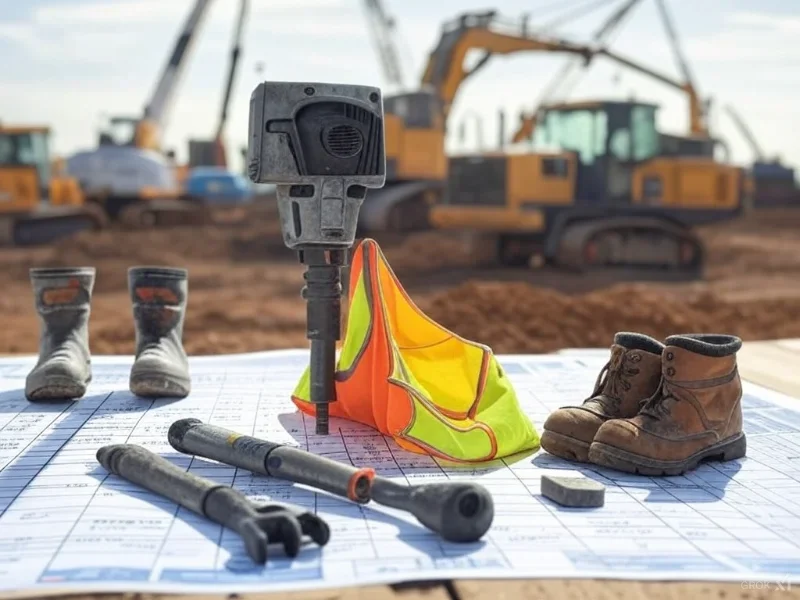
- Preparation: assemble calibrated gauges, deadweight tester, portable particle counter, test manifold, hand pump, infrared thermometer, PPE (gloves, eye protection), current P&ID, and project specifications. Verify isolation/LOTO and establish a safe test area with spill containment.
- Start interactive mode: create a new session, confirm project/asset IDs, and synchronise device time. Tick steps as completed, enter pressure/temperature readings in SI units, and add comments to capture context or deviations.
- Capture evidence: attach photos of gauges, tags, and relief test setups; upload calibration certificates and alarm screenshots. Use the app to time-stamp readings and link files to their specific steps.
- Export and share: generate an export as PDF/Excel, include signatures and embedded media links. Share with stakeholders and upload to the project document control system.
- Sign-off and archive: collect digital signatures from the commissioner and client representative, lock as-left setpoints, apply QR authentication, and archive the checklist with the asset’s QR code label for future retrieval.
Call to Action
- Start Checklist Tick off tasks, leave comments on items or the whole form, and export your completed report to PDF or Excel—with a built-in QR code for authenticity.
- Download Excel - Hydraulic Prop Commissioning Checklist
- Download PDF - Hydraulic Prop Commissioning Checklist
- View Image - Hydraulic Prop Commissioning Checklist
Cite & Embed
“Hydraulic Prop Commissioning Checklist by Quollnet”
with a link to
this source page.

FAQ
Question: What instruments do I need to commission hydraulic props accurately?
Question: How should I choose operating and relief pressures during commissioning?
Question: What acceptance criteria confirm a successful relief test?
Question: How do I document alarms and notifications effectively?
Question: Does this checklist include structural design of the props?
Related Articles
Broader reading and guidance connected to this checklist topic.


Is It Important To Customize Your Qr Code And How To Do It?
Related Checklists
Keep the workflow moving with nearby templates chosen from similar checklist content.