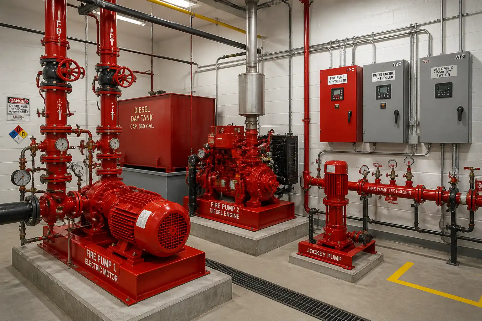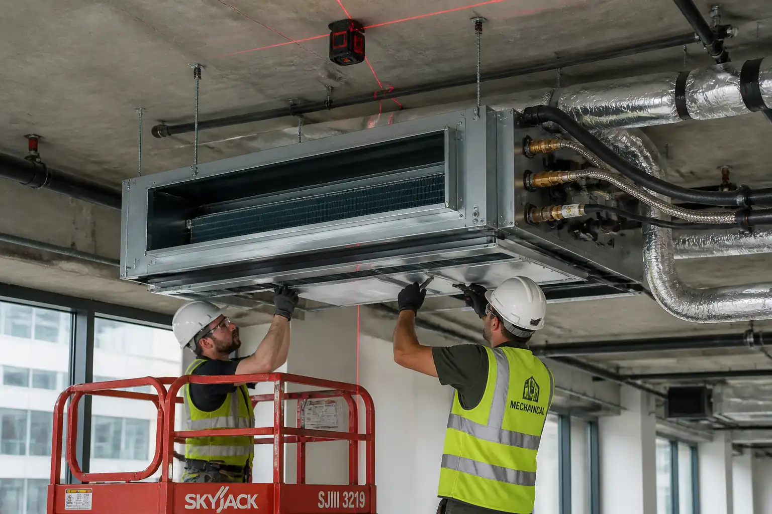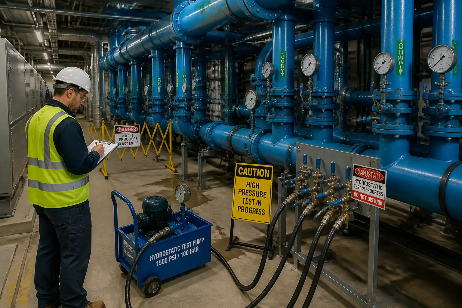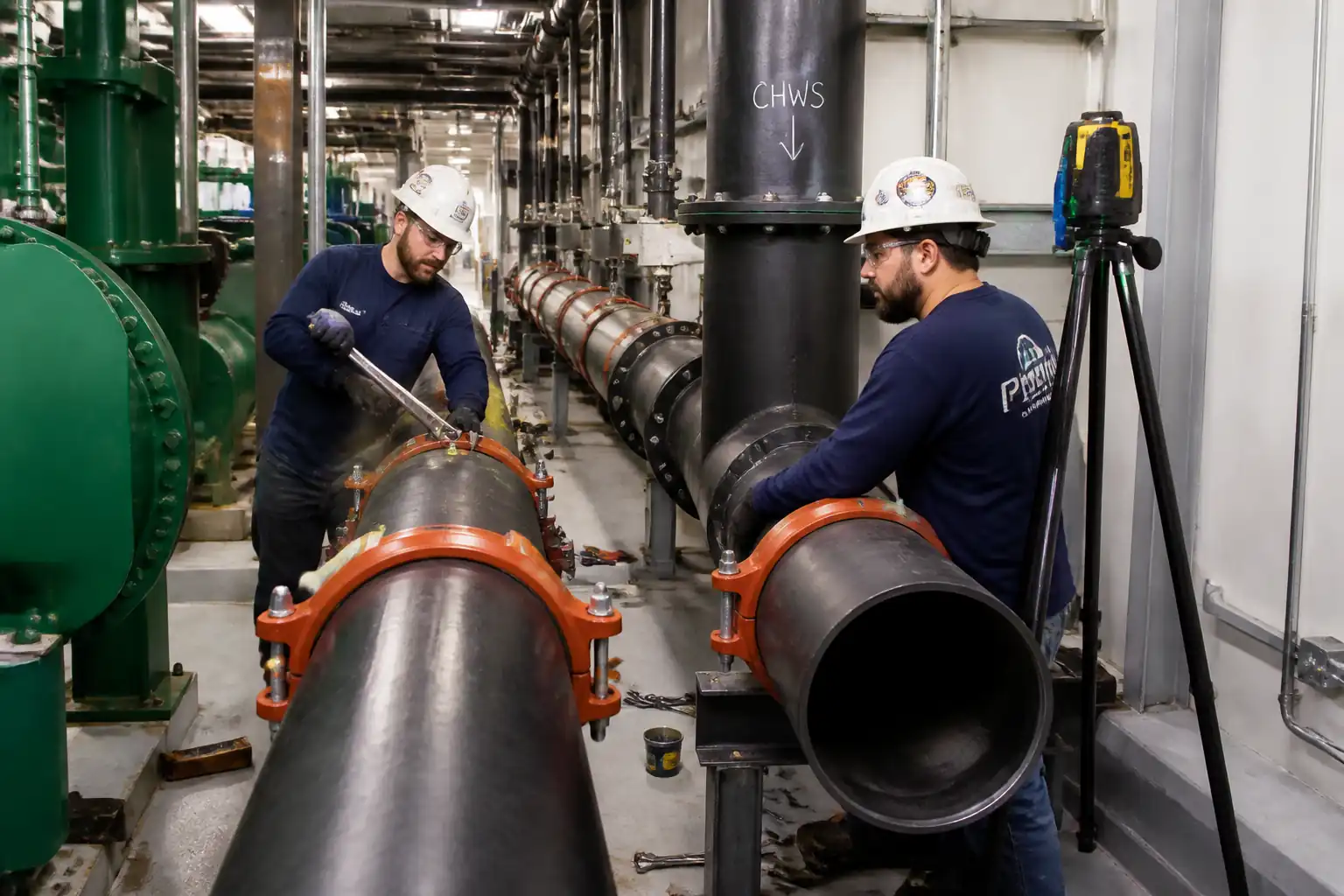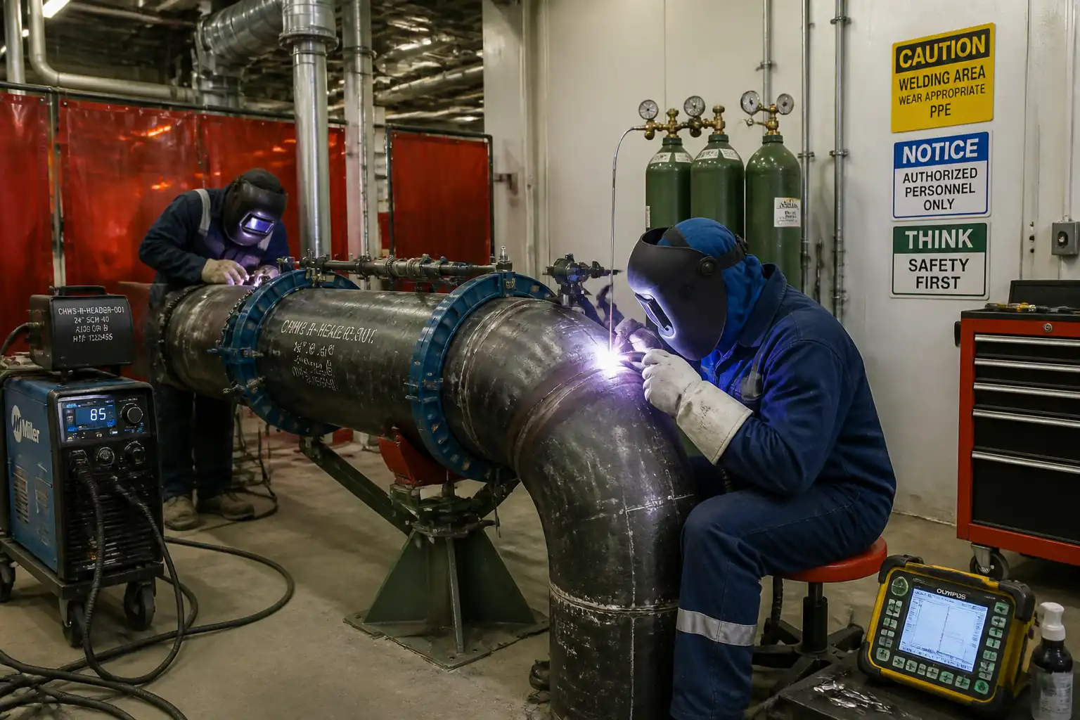

Method Statement – Installation of Chilled Water Pumps (End‑Suction and Split‑Case) – Method Statement
AI-assisted method statement with matching ITP, PDF download, and Excel export.
More than a static template
Unlike a downloadable Word or PDF template, this method statement is an AI-assisted editable starting point connected directly to a matching Inspection and Test Plan. Every section is structured, project-adaptable, and ready to export.
- AI-assisted drafting — Customize every section with AI for your specific project scope.
- Linked ITP — A matching inspection and test plan is generated alongside the method statement.
- Multiple export formats — Download as a formatted PDF or editable Excel spreadsheet.
- Editable starting point, not a final document — Review, verify, and adjust all content against your project requirements before use.
Static template vs. Quollnet workflow
| Feature | Static template | Quollnet |
|---|---|---|
| Project-specific content | Manual fill-in required | AI-assisted customization |
| Linked ITP | Separate document, no link | Matching ITP included |
| Export formats | Usually PDF only | PDF and Excel |
| Structured sections | Free-form layout | 13 standardized sections |
| Saved to your account | Local file only | Cloud-saved, reusable |
| Content accuracy | You verify everything | AI-assisted, you still verify |
| Cost | Often free but time-intensive | Free to customize and download |
What you can customize
When you save this method statement to your account, every section becomes editable. The following 13 sections are included:
- Scope — Defines the activity and its boundaries.
- References — Standards, specifications, and drawings.
- Responsibilities — Roles and accountabilities.
- Resources — Labour, plant, and equipment summary.
- Materials — Materials and compliance requirements.
- Equipment — Tools and equipment details.
- Prerequisites — Hold points and pre-conditions.
- Method sequence — Step-by-step construction sequence.
- Safety controls — HSE risk controls and PPE.
- Environmental controls — Environmental mitigation measures.
- QA/QC — Quality inspection and test requirements.
- ITP — Inspection and Test Plan table (has its own page).
- Attachments — Referenced drawings and documentation.
Why this method statement is used
This method statement is used to define and communicate the approved procedure for carrying out method statement – installation of chilled water pumps (end‑suction and split‑case) on site. It ensures the work is planned in advance, the correct resources and controls are in place, and all personnel understand responsibilities, sequence, quality requirements, and safety controls before work begins. It aligns site execution with the documented scope and acceptance expectations.
Who uses this method statement
This method statement is used by contractors, site supervisors, project engineers, QA/QC engineers, HSE officers, consultants, and client representatives. It serves as a shared reference for planning, execution, supervision, inspection, and approval of the activity on site.
When it is prepared and submitted
The method statement is prepared before the work activity starts and submitted as part of the pre-construction documentation package for review and approval.
Who reviews or approves it
The method statement is usually submitted to the client representative, consultant, resident engineer, or project management consultant for review and approval before the work commences.
Important approval note
This method statement is an AI-assisted editable starting point, not a pre-approved document. Before use on any project, all content must be reviewed and approved by the relevant parties (superintendent, principal contractor, or client representative) in accordance with your contract and project quality plan.
For example: if your specification requires a departure from a referenced standard, that departure must be documented and approved separately — this method statement will not capture that automatically. Always verify against your applicable drawings, specifications, and regulatory requirements.
Method statement content
Scope
Overview
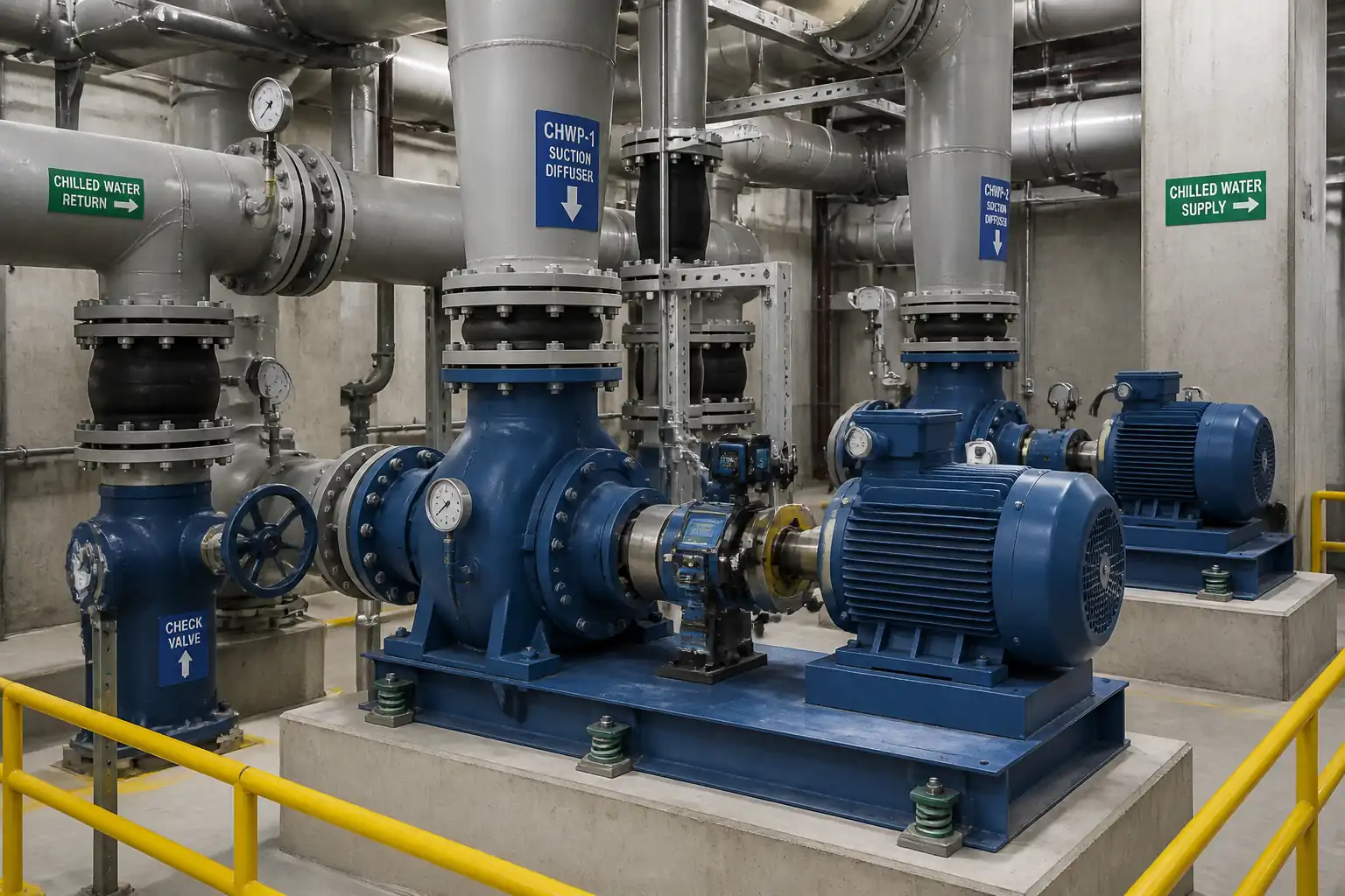
This method statement covers the complete installation of end‑suction and horizontal split‑case chilled water (CHW) pumps on inertia bases, including:
- Inertia base fabrication/placement and concrete pouring
- Installation of vibration isolators/seismic restraints [Verify per project specifications]
- Structural anchoring (cast‑in and/or post‑installed) and non‑shrink grouting
- Pump and motor placement, soft‑foot correction, laser alignment, and dial gauge verification
- Installation of suction diffusers, eccentric reducers, flexible connectors, discharge check/isolation valves
- Pipe strain prevention and verification at pump nozzles
- Electrical motor rotation check (uncoupled), coupling fitment, guarding
- Hydrostatic testing, flushing, and initial vibration measurements
- QA/QC documentation and approvals including anchor pull/proof tests and alignment/vibration reports
Out of Scope
- Full system chemical treatment program details (covered under separate procedures)
- Permanent control/automation programming (by controls contractor)
Key Objectives
- Deliver pumps installed to manufacturer’s tolerances, free from pipe strain
- Achieve alignment and vibration levels within ISO/HI recommendations
- Obtain QA/QC approvals for anchoring, grouting, alignment, and vibration prior to handover
References
| Document Type | Reference / Number | Revision | Notes |
|---|---|---|---|
| ASME B31.9 – Building Services Piping | Design, materials, hydrostatic test, and workmanship for CHW piping. | ||
| ACI 318 (Anchoring to Concrete provisions) and ACI 355.4 (Qualification of Post‑Installed Adhesive Anchors) [Verify edition per project] | Design and qualification of anchors; installation and approvals. | ||
| ASTM E488/E488M – Strength of Anchors in Concrete Elements | Field proof/pull testing methodology and acceptance referencing manufacturer data. | ||
| ASTM C1107 – Non‑Shrink Grout | Material properties and performance class for machinery base grouting. | ||
| ISO 20816‑3 (formerly ISO 10816‑3) – Vibration of rotating machinery; HI 9.6.4 – Pump vibration; ANSI/HI pump installation standards [Verify edition] | Vibration measurement/evaluation and installation best practice. | ||
| ISO 1940‑1 – Balance quality of rotating rigid bodies | Applicable where balancing verification is required. | ||
| ASTM F1554 (anchor rods), ASTM A307/A193 (bolting) [Verify per design] | Mechanical properties/grades for anchors and bolting. | ||
| ASHRAE Handbook – HVAC Systems and Equipment (Pumping and Hydronics) | Good practice for pump suction/discharge arrangements, NPSH, and commissioning. | ||
| ISO/IEC 17025 – Calibration and testing laboratories competence | Calibration traceability for alignment tools, gauges, torque wrenches. | ||
| Pump, motor, isolator, anchor, grout, suction diffuser, valve IOMs | IOM requirements supersede generic values where different. |
Responsibilities
| Role | Responsibility | Name / Party |
|---|---|---|
| PM | Ensures approved MS/ITP and materials; coordinates vendors. | Contractor |
| CM/SE | Verifies dimensions, sequencing, and tolerances; leads toolbox talks. | Contractor |
| QA/QC | Inspection requests, hold/witness points, test coordination, NCRs. | Contractor |
| HSE | Risk assessment, permits, monitoring, incident reporting. | Contractor |
| Rigger/Operator | Follow approved lifting plan and load charts. | Contractor |
| Fitters | Soft-foot correction, shimming, alignment, torqueing. | Contractor |
| TPI | Witness hold points (anchors, grouting, tests). | Independent |
| Engineer | Reviews IRs, approves milestones, punch list. | Engineer |
Resources
| Resource Type | Description | Quantity | Remarks |
|---|---|---|---|
| Manpower | Pump setting, alignment, bolting | 3–6 | |
| Manpower | Lifting & movement | 2–3 | |
| Manpower | Operate lifting equipment | 1 | |
| Manpower | Inertia base and grout | 3–5 | |
| Manpower | Inspections and records | 1 | |
| Manpower | Safety oversight | 1 |
Materials
| Material | Specification / Grade | Quantity | Remarks |
|---|---|---|---|
| Pump + Motor | As per BOQ | ||
| Inertia base | Per pump | ||
| Concrete | ASTM/EN mix design | As designed | |
| Grout | As required | ||
| Anchors | Per drawing | ||
| Isolators | Per pump | ||
| Fittings | Per layout | ||
| Valves | Per layout | ||
| Shims | Sets per pump |
Equipment
| Equipment | Capacity / Type | Quantity | Inspection Required |
|---|---|---|---|
| Crane/Forklift | Per lifting plan | As required | Yes |
| Rigging gear | Per plan | Sets | Yes |
| Laser aligner | 1 | Yes | |
| Dial gauges | 2 | Yes | |
| Level | 1 | Yes | |
| Torque wrenches | Set | Yes | |
| Mixers/Vibrators | As required | Yes | |
| Hammer drill | 1–2 | Yes | |
| Test pump | 1 set | Yes |
Prerequisites
- Approved IFC drawings, pump schedules, and coordinated layout/shop drawings
- Approved submittals for pumps, motors, isolators, anchors, grout, suction diffusers, valves
- Approved lifting plan and permits to work (lifting, hot work if any, chemical handling, concrete pour) [Verify per project HSE plan and local regulations]
- Anchor design calculations and layout issued; concrete strength of foundation verified via test reports (≥ 75% of f'c before drilling/post‑install; ≥ design f'c before proof testing) [Verify]
- Equipment calibration certificates current (laser aligner, torque wrenches, gauges)
- Plantroom access and housekeeping prepared; elevations and foundation dimensions surveyed
- Temporary power available for tools and test equipment; lighting and ventilation adequate
- Pre‑start coordination/TBT completed with all trades; exclusion zones demarcated
- Manufacturer IOMs available; thermal growth data or offsets obtained from OEM [Verify]
- Piping supports and guides installed/adjustable near pump nozzles prior to connection
- Isolation of live services in work area confirmed; LOTO plan prepared for rotation checks
- Environmental controls in place (washout bin, spill kits, wastewater management)
Method Sequence
| Step | Activity | Description | Responsibility | Inspection / Hold Point |
|---|---|---|---|---|
| 1 | Setting out and foundation verification | Survey foundation top; verify footprint, elevation, flatness ≤ 2 mm over base footprint [Verify]; confirm sleeves/openings and drain locations. | Site Engineer/Surveyor | Dimension and level check |
| 2 | Inertia base reinforcement, anchors, and formwork | Fix steel frame/rebar per approved drawing; position cast‑in anchors/jacking bolts; install formwork with chamfers and grout lips. | Construction Manager | Pre‑pour inspection (IR) |
| 3 | Inertia base concrete pour and curing | Place concrete (slump 75–100 mm [Verify]); vibrate to avoid voids; finish levelness ≤ 1 mm/m; cure min 7 days (or per mix/curing compound). | Concrete Crew | Concrete delivery and placement |
| 4 | Mount vibration isolators/seismic snubbers | Install isolators under inertia base or base frame; set leveling nuts to achieve target static deflection; install snubbers/restraints where specified. | Mechanical Fitters | Visual and level check |
| 5 | Place pump and motor on base | Rig and set pump skid; use shims/wedges to achieve preliminary level; check soft foot at motor using feeler gauges/laser. | Millwrights | Soft‑foot check |
| 6 | Baseplate/inertia base grouting | Prepare substrate (clean, roughened); pre‑wet 24 h; install head box; mix flowable ASTM C1107 grout; place from one side to avoid air; maintain min 25–50 mm thickness [Verify]; cure per data sheet (typically 24–48 h before torque). | Mechanical/Grout Crew | Witness grout placement (Hold) |
| 7 | Anchor installation and torque/proof testing | For post‑installed anchors: drill to depth with approved bit; clean holes (blow/brush/blow or vacuum) per ETA; inject adhesive; place studs with embedment marks; cure per temperature chart. Torque to manufacturer spec; conduct proof/pull tests per plan. | QA/QC + Fitters | Hold for witness |
| 8 | Piping connection – suction side | Install eccentric reducer (flat on top), flexible connector, suction diffuser/strainer per flow direction; maintain straight run to pump: typically ≥ 5D (may reduce per diffuser datasheet) [Verify]; support piping so no nozzle loads. | Piping Crew | Fit‑up inspection |
| 9 | Piping connection – discharge side | Install check valve then isolation valve per arrow; flexible connector as specified; provide supports/guides to prevent loads to pump. | Piping Crew | Fit‑up inspection |
| 10 | Preliminary cold laser alignment (uncoupled) | Rough set shims; perform laser alignment with coupling removed or loosened; compensate for anticipated thermal growth per OEM. | Millwrights | Alignment reading review |
| 11 | Dial indicator checks | Measure coupling face and rim Total Indicator Runout (TIR); confirm shaft runout within limits. | Millwrights | QC check |
| 12 | Pipe strain verification at nozzles | With flanges bolted finger‑tight, slacken bolts to observe movement; measure lift/shift with dial/feeler; adjust supports/guides until negligible. | Piping Crew + QA/QC | Witness test |
| 13 | Electrical connections and rotation check | Complete wiring and earthing; uncouple and bump motor ≤ 1 s to verify correct rotation; correct phasing if needed. | Electrical Team | LOTO and rotation sign‑off |
| 14 | Hydrostatic pressure test (connected piping) | Isolate pumps if required; test at 1.5× design pressure or per spec [Verify]; hold ≥ 2 h; protect equipment/valves as needed. | QA/QC + Piping Crew | Hold for test witness |
| 15 | Flushing and cleaning | Flush at velocity ≥ 1.5–2.0 m/s [Verify]; use temporary strainers; remove debris; record turbidity/clarity; reinstate final strainers. | Commissioning Team | Flow/velocity verification |
| 16 | Final coupling fitment and guard | Install coupling to OEM torque sequence; fit guard with interlocks (if any); affix labels. | Millwrights | Visual/torque check |
| 17 | Initial run and vibration measurement | Start pump; bleed air; stabilize temperature; record vibration at bearings in three axes using RMS velocity; record noise and temperature. | Commissioning Team | Witness test |
| 18 | Hot alignment verification (if required) | Shut down safely; re‑check alignment after thermal soak; adjust shims as needed and re‑verify. | Millwrights | QC review |
| 19 | Punch list and handover | Close NCRs/SNs; submit as‑built redlines, O&M, test certificates, guarantees. | QA/QC + PM | Final inspection |
Safety Controls
Task-specific risk controls
1) Hazard: Lifting pumps/inertia bases
- Likely consequence: Crush injuries, dropped loads, rigging failure
- Engineering/procedural control: Approved lifting plan; select lifting points per OEM; use certified slings/spreader; maintain exclusion zone; tag‑line control; pre‑lift meeting
- Required PPE: Hard hat, safety boots, gloves, eye protection, high‑vis
- Collective preventive measure: Barricades and banksman control; load path planning
- Inspection/permit/supervision: Lifting permit; daily crane/tackle inspection; competent rigger and operator; weather/wind check [Verify per project HSE plan and local regulations]
2) Hazard: Drilling/post‑installed anchors (silica dust, noise, ejection)
- Likely consequence: Respiratory harm, eye injury, hearing loss
- Engineering/procedural control: Integrated dust extraction; wet drilling if permitted; drill stops for depth; secure work area; use correct bit size
- Required PPE: FFP3/N95 respirator, safety glasses/face shield, hearing protection, gloves
- Collective preventive measure: Local exhaust ventilation; debris containment
- Inspection/permit/supervision: Tool PAT, bit condition check; SDS compliance; supervision for adhesive handling
3) Hazard: Epoxy/chemical adhesive exposure
- Likely consequence: Dermatitis, eye irritation, sensitization
- Engineering/procedural control: Follow SDS; mixing/applicator training; no skin contact; spill kits
- Required PPE: Chemical‑resistant gloves, goggles, long sleeves
- Collective preventive measure: Ventilation in plantroom; dedicated mixing area with tray
- Inspection/permit/supervision: Chemical handling permit; SDS on site; first‑aid eyewash
4) Hazard: Concrete/grout handling
- Likely consequence: Cement burns, slips on wet surfaces
- Engineering/procedural control: Controlled pour area; use head box; clean spills immediately; safe access/egress
- Required PPE: Waterproof gloves, eye protection, long sleeves, rubber boots
- Collective preventive measure: Wet area signage and barriers; non‑slip mats
- Inspection/permit/supervision: Pre‑pour checklist; curing area cordoned off
5) Hazard: Pinch/entanglement during alignment and coupling
- Likely consequence: Finger injuries, lacerations
- Engineering/procedural control: LOTO; keep guards installed except during alignment with equipment isolated; use proper tools and shims; hands‑off while rotating shafts manually
- Required PPE: Gloves, eye protection
- Collective preventive measure: Guarding reinstated immediately after checks
- Inspection/permit/supervision: LOTO permit; supervisor sign‑off before energization
6) Hazard: Uncontrolled energization/rotation check
- Likely consequence: Entanglement, electric shock
- Engineering/procedural control: Electrical LOTO; uncoupled bump test ≤ 1 s; confirm direction arrow; barriers around rotating parts
- Required PPE: Electrical‑rated gloves (if applicable), eye protection
- Collective preventive measure: Temporary guards/shields; lockable isolators
- Inspection/permit/supervision: Electrical permit; competent electrician; test documentation
7) Hazard: Pressure testing
- Likely consequence: Hose whip, component failure, water jets
- Engineering/procedural control: Calibrated gauges; rated hoses; gradual pressurization; evacuate non‑essential personnel; guard/blank off vents
- Required PPE: Eye/face protection, gloves, boots
- Collective preventive measure: Test bay barriers; warning signage
- Inspection/permit/supervision: Pressure test permit; hold point witness; leak rectification plan
8) Hazard: Confined/ congested plantroom, manual handling
- Likely consequence: Strains, trips, musculoskeletal injury
- Engineering/procedural control: Material staging; mechanical aids; clear walkways; weight limits observed
- Required PPE: Boots, gloves
- Collective preventive measure: Housekeeping regime; lighting enhancement
- Inspection/permit/supervision: Manual handling training; routine housekeeping inspections
9) Hazard: Noise and vibration exposure
- Likely consequence: Hearing damage
- Engineering/procedural control: Use hearing protection; limit exposure time; schedule noisy tasks
- Required PPE: Ear defenders/earplugs
- Collective preventive measure: Acoustic screens where practical
- Inspection/permit/supervision: Noise assessment as required
10) Hazard: Hot works (if any cutting/welding of supports)
- Likely consequence: Burns, fire, fumes
- Engineering/procedural control: Hot work permit; fire watch; spark containment; portable extinguishers
- Required PPE: Welding shield, gloves, FR clothing
- Collective preventive measure: Fire blankets; dedicated hot work zone
- Inspection/permit/supervision: Gas leak tests; fire watch 30 min post‑work [Verify per project rules]
Environmental Controls
- Concrete/grout washout: Use lined washout container; no discharge to drains; dispose via licensed handler [Verify per local regulations]
- Dust control: Vacuum extraction on drills; damp down sweeping; sealed waste bags for fines
- Chemical/epoxy waste: Store cartridges in trays; segregate hazardous waste; SDS-compliant disposal
- Flushing water: Capture/neutralize treatment chemicals (biocide/inhibitor) before discharge; sample and document per permit
- Noise management: Limit hours; maintain equipment; use acoustic barriers if near receptors
- Spill prevention: Drip trays under pumps during oil/grease application; spill kits accessible; immediate cleanup
- Material efficiency: Order grout/concrete to quantity; reuse shims where allowed; recycle packaging
- Energy use: Shut down idle plant; optimize crane picks to reduce running time
QA/QC
General
- Use approved materials and calibrated instruments (ISO/IEC 17025 traceability).
- Raise IRs for hold/witness points as listed in ITP.
Key acceptance criteria
- Foundation level/flatness within specified tolerances (≤ 1 mm/m finish; elevation ±3 mm) [Verify per project]
- Inertia base mass ratio 2–3× rotating mass [Verify]; anchors positioned ±3 mm
- Grout: ASTM C1107; full bearing; strength per data sheet (28‑day ≥ 50 MPa typical) [Verify]
- Anchors: Installation per ETA/ICC‑ES; torque per OEM; proof test sample ≥ 5% (≥ 3/lot) at manufacturer‑recommended proof load; displacement within limits [Verify]
- Soft foot corrected to ≤ 0.05 mm
- Laser alignment: Offset ≤ 0.05 mm; angular ≤ 0.05 mm/100 mm (or OEM) [Verify]
- Dial indicator TIR: Face/rim ≤ 0.05 mm; shaft runout per OEM (typ. ≤ 0.03 mm)
- Pipe strain: ≤ 0.5 mm movement at nozzle when bolts loosened [Verify]
- Hydrotest: 1.5× design pressure; hold ≥ 2 h; no leakage/pressure drop beyond gauge tolerance
- Flushing: Velocity ≥ 1.5–2.0 m/s; strainers cleaned; water clarity achieved
- Vibration: Within ISO 20816‑3/HI 9.6.4 and OEM limits (typ. ≤ 2.8–4.5 mm/s RMS depending on machine class) [Verify]
Records
- Delivery inspections; concrete/grout COCs and test results; anchor installation logs; pull test reports; alignment reports (cold/hot); hydrotest and flushing logs; vibration reports; torque sheets; IRs and approvals; as‑built redlines.
Nonconformance
- Record NCRs for out‑of‑tolerance results; implement corrective actions (re‑grout, re‑align, re‑support piping, replace anchors) and retest.
Hold/Witness (typical)
- Grouting placement (Hold), Anchor proof testing (Hold), Hydrotest (Hold), Initial vibration run (Witness).
Attachments
- Approved shop drawings and coordination layouts
- Lifting plan and rigging certificates
- Anchor design calculations and layout drawings; ETA/ICC‑ES reports
- Concrete/grout mix approvals; COCs and test results
- Manufacturer IOMs (pump, motor, isolators, anchors, grout, valves)
- Pre‑pour, grouting, and anchor installation checklists
- Anchor pull/proof test reports
- Laser alignment and dial indicator report templates (cold/hot)
- Hydrostatic test and flushing logs
- Vibration measurement report template (ISO 20816‑3/HI 9.6.4)
- HSE risk assessment, permits, and toolbox talk records
This content is a read-only public reference. Download or customize to get an editable version.
ITP preview
The first inspection activities from the linked ITP for Method Statement – Installation of Chilled Water Pumps (End‑Suction and Split‑Case):
| Activity | Inspection / Test | Acceptance Criteria | Responsibility | Record |
|---|---|---|---|---|
| Pre-installation verification | Check drawings, materials approvals, calibration | All approvals/calibration current; site ready | QA/QC, Site Engineer | IR, checklist |
| Foundation and setting out | Dimensions, levelness | Within drawing tolerance; finish ≤ 1 mm/m [Verify] | QA/QC, Surveyor | Survey report, IR |
| Inertia base rebar/anchors/formwork (pre‑pour) | Anchor position, rebar, cleanliness | Anchor position ±3 mm; cleanliness OK | QA/QC, Engineer, Consultant | IR with photos |
Showing 3 of 19 inspection activities. View full ITP →
Related Inspection and Test Plan
An Inspection and Test Plan (ITP) is available for Method Statement – Installation of Chilled Water Pumps (End‑Suction and Split‑Case). The ITP defines the inspection activities, acceptance criteria, hold and witness points, responsible parties, and records required to verify the work described in this method statement.
View the Method Statement – Installation of Chilled Water Pumps (End‑Suction and Split‑Case) ITP →Frequently asked questions
Continue with related Quollnet resources connected to this method statement.