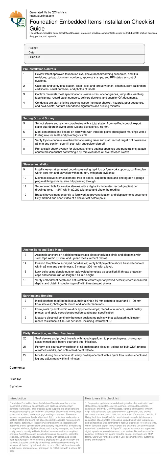
Foundation Embedded Items Installation Checklist
Definition: Foundation Embedded Items Installation Checklist guides site engineers installing sleeves, anchors, and earthing in foundations, confirming positions and fixity while excluding reinforcement checks.
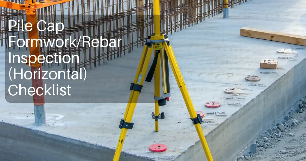
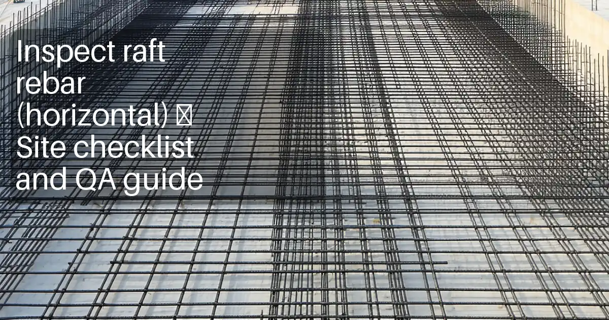
- Covers sleeves, anchor bolts, and earthing in concrete foundations.
- Prevents misalignment, rework, programme delays, and expensive core drilling.
- Survey-led methods, rigid templates, fixity controls, measurable acceptance tolerances.
- Interactive, commentable, export, QR code authenticated records and sign-offs.
Foundation Embedded Items Installation Checklist enables precise placement of sleeves, anchor bolts, and earthing components in concrete foundations. This practical guide supports site engineers and inspectors managing cast-in items, embedded sleeves and inserts, base plates and anchors, and earthing/grounding conductors. The scope focuses on positions, levels, alignment, fixity, protection, and evidence capture before and during the pour. It explicitly excludes reinforcement bar checks, detailing, or inspection; coordinate those separately per approved project specifications and authority requirements. By following survey-led methods, rigid templates, and bracing strategies, you’ll avoid costly rework, misaligned bolts, blocked services, and non-compliant earthing. Acceptance cues include dimensional tolerances, calibrated readings, continuity measurements, photos with scales, and signed hold-point releases. The outcome is predictable fit-up of steelwork and services, traceable continuity of earthing, and clean sleeves ready for services, all backed by authenticated records. Start in interactive mode to tick items, add comments, and export as PDF/Excel with a secure QR code.
- Ensure accurate sleeves, anchors, and earthing installation within defined tolerances using survey control, rigid templates, and independent bracing. Reduce misalignment, blocked openings, and rework by verifying positions, levels, and fixity before the pour and documenting everything with photos, reports, and calibrated readings.
- De-risk programme and downstream trades by validating bolt projections, plumbness, sleeve gradients, and clearances. Acceptance cues include total station deviations, inclinometer readings, torque logs where specified, and continuity tests. Evidence-based sign-offs support smooth steel erection and services routing upon formwork strike.
- Interactive online checklist with tick, comment, and export features secured by QR code. Capture photos, readings, and approvals in one place, then share authenticated PDFs/Excels across teams for traceable QA from set-out to pour readiness.
- Maintain tight scope control: embedded items only, excluding reinforcement checks or bar inspections. Coordinate any reinforcement interfaces through shop drawings and RFIs, but verify embedded items’ fixity, protection against concrete ingress, and survey as-builts per approved project specifications and authority requirements.
Pre-Installation Controls
Setting Out and Survey
Sleeves Installation
Anchor Bolts and Base Plates
Earthing and Bonding
Fixity, Protection, and Pour Readiness
Scope, Benefits, and Boundaries
This checklist focuses on embedded items in foundations: sleeves for services, anchor bolts and base plates, and earthing conductors. It helps site engineers achieve precise positions, levels, alignment, and fixity so downstream trades connect seamlessly. You will use survey control, rigid templates, independent bracing, and protective measures to avoid blocked penetrations, misaligned steelwork, and non-compliant earthing. The checklist excludes reinforcement checks, bar detailing, or rebar inspections; coordinate those separately per approved project specifications and authority requirements. Acceptance evidence includes photos with scales, stake-out and as-built CSVs, inclinometer readings, continuity measurements, and hold-point releases. When followed diligently, the result is predictable bolt fit-up, clear sleeves ready for services, durable protected threads, and traceable records from preparation to pour readiness. The structured flow mirrors real site stages to reduce risk and save time while enhancing accountability across teams.
- Embedded items only; reinforcement checks are excluded from scope.
- Use survey control and templates for accurate set-out.
- Independently brace to prevent movement during pour.
- Capture calibrated readings and photo evidence.
- Hold-point releases before any concrete placement.
Methods, Tolerances, and Acceptance Cues
Apply survey-led setting out using a calibrated total station, marking clear centerlines and offsets on formwork. For sleeves, target plan position within ±10 mm and elevation within ±5 mm, protecting internal diameters and maintaining any required gradients within ±0.2%. For anchors, verify bolt circle and spacing within ±2 mm, projection above finished concrete within ±3 mm, and plumbness ≤ 2 mm per 300 mm. Assemble using rigid templates and secure with double nuts or approved tack welds, then cap threads. For earthing, maintain adequate separation from sleeves and confirm continuity with a calibrated multimeter to a specified threshold. Acceptance is evidenced by stake-out and as-built reports, inclinometer screenshots, continuity readings, and timestamped photos showing scales and witness marks. A simple pre-pour recheck often prevents major rework; for example, a 4 mm bolt circle shift was detected and corrected before concrete placement, averting baseplate slotting and schedule impacts.
- Sleeves: ±10 mm plan, ±5 mm elevation.
- Anchors: ±2 mm spacing, ±3 mm projection.
- Plumbness within 2 mm per 300 mm height.
- Gradients within ±0.2% for sloped sleeves.
- Continuity at or below specified threshold.
Fixity, Pour Readiness, and Evidence Capture
Prevent movement during the pour with independent bracing to formwork, rigid anchor templates, protective caps, and sealed sleeves. Mark witness lines on templates and formwork to detect shifts. Right before concrete placement, complete a hold-point inspection, re-verify positions with a quick total station sweep, and ensure capped threads and sealed sleeves are intact. During the first lift, spot-check anchors and critical sleeves for displacement. For earthing, verify protected joints, applied corrosion coatings, and continuity readings are recorded. Capture evidence consistently: photos with scales, CSV exports from instruments, calibration certificates, batch numbers, and sign-offs. Store everything in a single source so supervisors and auditors can instantly trace decisions and approvals. This disciplined approach secures dimensional control, avoids expensive core drilling or baseplate modifications, and yields clean, verifiable records.
- Brace independently; avoid movement during pour.
- Mark witness lines to detect any shift.
- Seal sleeves and protect bolt threads.
- Complete hold-point checks pre-pour.
- Centralize photos, readings, and sign-offs.
How to Use This Checklist Effectively
- Preparation: gather approved drawings/schedules, calibrated total station/laser, templates, sleeves, anchors, earthing tape/clamps, caps/foam, and PPE. Confirm access, lighting, and weather window. Align hold-points and pour sequence with supervision, and preload document numbers, batch data, and instrument IDs into the checklist.
- Using the Interactive Checklist: start interactive mode, tick items as completed, attach photos with scales, upload CSVs from instruments, and log readings. Use comments to resolve clashes or RFIs in real time. When complete, export to PDF/Excel and share the QR-authenticated record with stakeholders.
- Sign-Off: capture inspector and supervisor digital signatures, record dates and pour section IDs, and archive the package. Distribute the signed report to design, steelwork, and MEP teams. Store QR-verified records in your document control system for audits and handover.
Call to Action
- Start Checklist Tick off tasks, leave comments on items or the whole form, and export your completed report to PDF or Excel—with a built-in QR code for authenticity.
- Download Excel - Foundation Embedded Items Installation
- Download PDF - Foundation Embedded Items Installation
- View Image - Foundation Embedded Items Installation
Cite & Embed
“Foundation Embedded Items Installation by Quollnet”
with a link to
this source page.

FAQ
Question: What tolerances should I apply to sleeves and anchor bolts in foundations?
Question: What evidence should I capture to prove positions and fixity before pouring?
Question: How do I handle earthing installation within the foundation pour?
Question: What if my set-out shows a clash between a sleeve and anchor group?
Related Articles
Broader reading and guidance connected to this checklist topic.


Requisition Form: Materials, Services, Budget Control, And Logs

Is It Important To Customize Your Qr Code And How To Do It?

Improve Your Project Handover Process With Snag List Tracking App
Related Checklists
Keep the workflow moving with nearby templates chosen from similar checklist content.