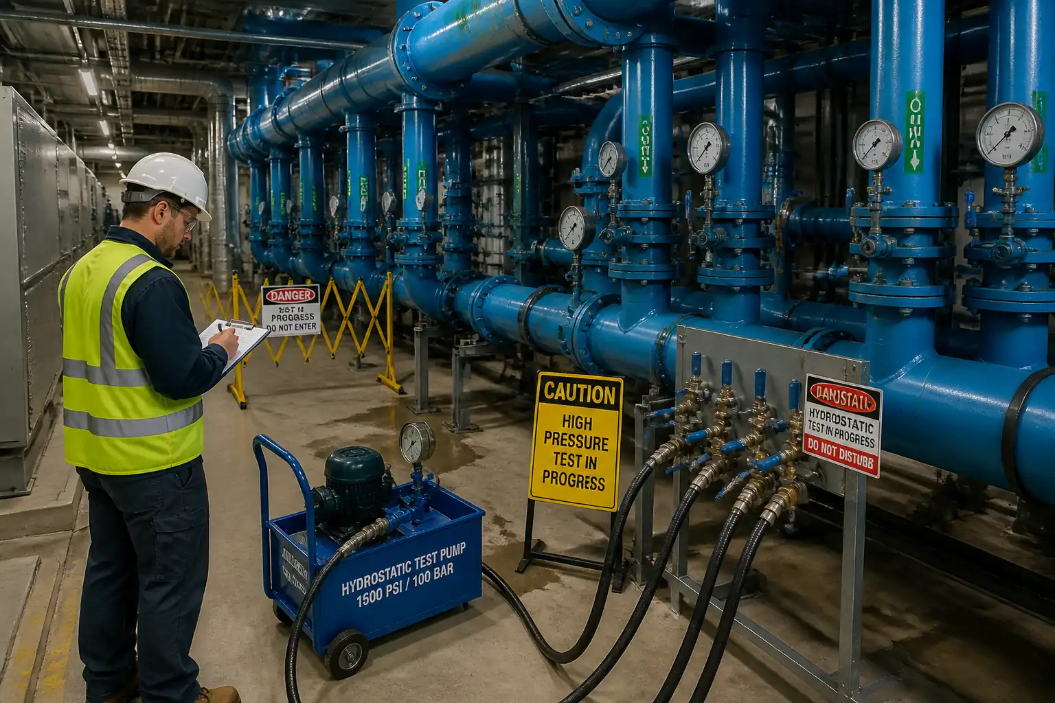

Method Statement: Hydrostatic Pressure Testing of Chilled Water (CHW) Piping Networks – Method Statement
AI-assisted method statement with matching ITP, PDF download, and Excel export.
More than a static template
Unlike a downloadable Word or PDF template, this method statement is an AI-assisted editable starting point connected directly to a matching Inspection and Test Plan. Every section is structured, project-adaptable, and ready to export.
- AI-assisted drafting — Customize every section with AI for your specific project scope.
- Linked ITP — A matching inspection and test plan is generated alongside the method statement.
- Multiple export formats — Download as a formatted PDF or editable Excel spreadsheet.
- Editable starting point, not a final document — Review, verify, and adjust all content against your project requirements before use.
Static template vs. Quollnet workflow
| Feature | Static template | Quollnet |
|---|---|---|
| Project-specific content | Manual fill-in required | AI-assisted customization |
| Linked ITP | Separate document, no link | Matching ITP included |
| Export formats | Usually PDF only | PDF and Excel |
| Structured sections | Free-form layout | 13 standardized sections |
| Saved to your account | Local file only | Cloud-saved, reusable |
| Content accuracy | You verify everything | AI-assisted, you still verify |
| Cost | Often free but time-intensive | Free to customize and download |
What you can customize
When you save this method statement to your account, every section becomes editable. The following 13 sections are included:
- Scope — Defines the activity and its boundaries.
- References — Standards, specifications, and drawings.
- Responsibilities — Roles and accountabilities.
- Resources — Labour, plant, and equipment summary.
- Materials — Materials and compliance requirements.
- Equipment — Tools and equipment details.
- Prerequisites — Hold points and pre-conditions.
- Method sequence — Step-by-step construction sequence.
- Safety controls — HSE risk controls and PPE.
- Environmental controls — Environmental mitigation measures.
- QA/QC — Quality inspection and test requirements.
- ITP — Inspection and Test Plan table (has its own page).
- Attachments — Referenced drawings and documentation.
Why this method statement is used
This method statement is used to define and communicate the approved procedure for carrying out method statement: hydrostatic pressure testing of chilled water (chw) piping networks on site. It ensures the work is planned in advance, the correct resources and controls are in place, and all personnel understand responsibilities, sequence, quality requirements, and safety controls before work begins. It aligns site execution with the documented scope and acceptance expectations.
Who uses this method statement
This method statement is used by contractors, site supervisors, project engineers, QA/QC engineers, HSE officers, consultants, and client representatives. It serves as a shared reference for planning, execution, supervision, inspection, and approval of the activity on site.
When it is prepared and submitted
The method statement is prepared before the work activity starts and submitted as part of the pre-construction documentation package for review and approval.
Who reviews or approves it
The method statement is usually submitted to the client representative, consultant, resident engineer, or project management consultant for review and approval before the work commences.
Important approval note
This method statement is an AI-assisted editable starting point, not a pre-approved document. Before use on any project, all content must be reviewed and approved by the relevant parties (superintendent, principal contractor, or client representative) in accordance with your contract and project quality plan.
For example: if your specification requires a departure from a referenced standard, that departure must be documented and approved separately — this method statement will not capture that automatically. Always verify against your applicable drawings, specifications, and regulatory requirements.
Method statement content
Scope
Work Scope
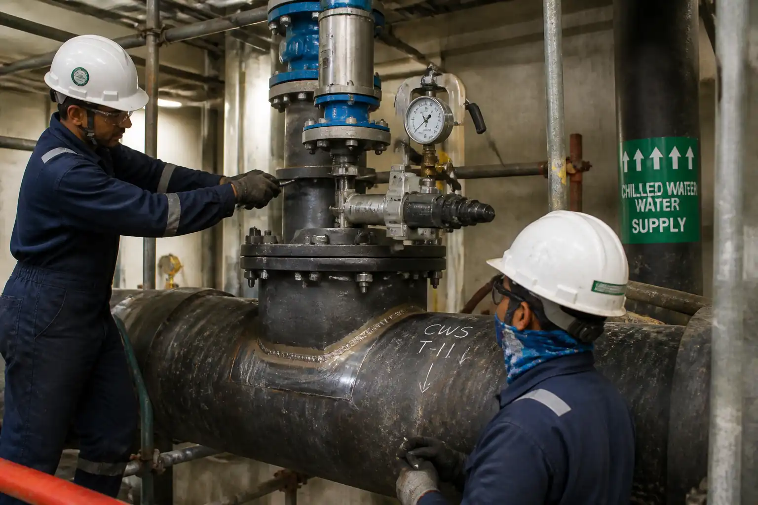
This method statement covers planning, preparation, execution, monitoring, and documentation of hydrostatic pressure testing of Chilled Water (CHW) supply and return piping networks, including:
- Sectional isolation of test boundaries (exclusion of coils/equipment not rated for test pressure).
- Provision and installation of high-point vents and low-point drains for complete air removal and controlled drainage.
- Filling, de-aeration, gradual pressurization to 1.5 × Working Pressure (WP) [Verify per project specifications], stabilization, and 24-hour hold with periodic readings.
- Monitoring using calibrated pressure gauges and temperature measurement for pressure correction.
- Identification and rectification of leaks, retesting as required.
- Consultant/Client witness at defined hold points.
- Safe drainage, environmental protection, and reinstatement post-test.
Exclusions
- Chemical cleaning/flush and passivation (covered under separate method: pre-commission cleaning per BSRIA BG 29).
- Insulation works (to occur after successful pressure testing unless otherwise approved).
References
| Document Type | Reference / Number | Revision | Notes |
|---|---|---|---|
| Standard | ASME B31.9 (latest) | ||
| Standard | EN 837-1; ASME B40.100 | ||
| Standard | ISO/IEC 17025 | ||
| Guidance | CIBSE Code W (latest) | [Verify regional applicability] | |
| Guidance | BSRIA BG 29; BG 50 | [Verify per project] | |
| Contract Docs |
Responsibilities
| Role | Responsibility | Name / Party |
|---|---|---|
| PM | Project Manager | Contractor |
| Engineer | Mechanical Engineer | Contractor |
| QA/QC | QA/QC Engineer | Contractor |
| HSE | HSE Officer | Contractor |
| Supervisor | Supervisor | Contractor |
| Cx Manager | Commissioning Manager | Contractor |
| Consultant | Consultant | Client |
Resources
| Resource Type | Description | Quantity | Remarks |
|---|---|---|---|
| Manpower | Assembly of blinds, vents, drains; tightening; leak rectification. | As required | |
| Manpower | Provides safe power supply to pumps and datalogging equipment. | 1 | |
| Manpower | Installs access for high-point vents/gauges where needed. | As required | |
| Manpower | Assists with heavy blinds/temporary headers handling. | As required |
Materials
| Material | Specification / Grade | Quantity | Remarks |
|---|---|---|---|
| Water | As required | ||
| As required | |||
| As required | |||
| As required | |||
| As required |
Equipment
| Equipment | Capacity / Type | Quantity | Inspection Required |
|---|---|---|---|
| Pump | Flow/Pressure per section | 1 | Yes |
| Gauges | ≥2 per section | Yes | |
| 1 | Yes | ||
| As required | No | ||
| As required | Yes | ||
| As required | Yes |
Prerequisites
Pre-Test Readiness
- Approved IFC drawings, pressure test calculations, and test packs available.
- Working Pressure (WP) and maximum allowable test pressure confirmed for each section. Equipment (coils, terminal units, pumps, heat exchangers) isolated or bypassed if rated below test pressure. [Verify per project specifications]
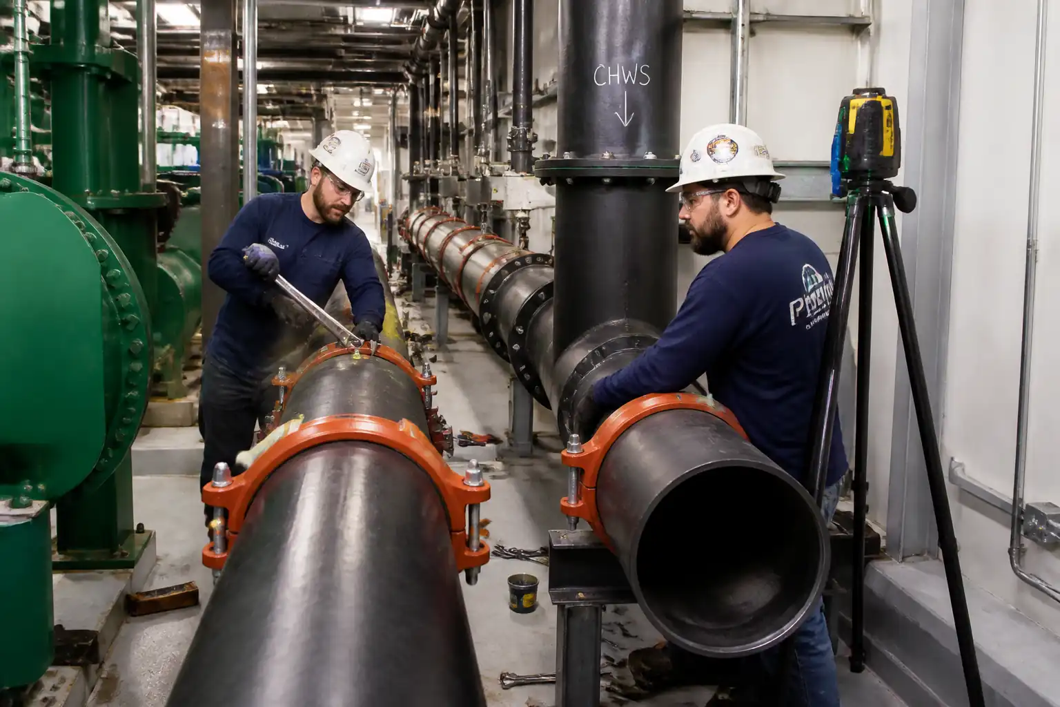
- Mechanical completion of test section: joints made, supports installed and tightened, temporary vents/drains installed, expansion devices neutralized/temporarily restrained as applicable per manufacturer.
- Valves positioned as per boundary plan; non-return valves made testable (e.g., by bypass or removal) or excluded.
- Instruments: pressure gauges and thermometers calibrated and labeled; certificates current (within 6–12 months) [Verify per project].
- Area secured: barricades and signage; escape routes kept clear; emergency plan briefed.
- PTW/Permit to Test issued and signed. Electrical supply to pump verified by electrician with RCD/ELCB protection.
- Flange bolts/grooved couplings torque-checked per manufacturer; witness marks applied.
- Drainage route identified; containment (tanks/IBC) and filtration available; environmental permission obtained where required.
- Consultant/Client notified of witness schedule (≥48 hrs notice or per contract).
Method Sequence
| Step | Activity | Description | Responsibility | Inspection / Hold Point |
|---|---|---|---|---|
| 1 | Define and Isolate Test Section | Install blinds/spades or disconnect spools; ensure all equipment not rated for test pressure is isolated; open vents at high points and drains at low points. | Mechanical Engineer / Supervisor | Boundary check vs. test isometric. |
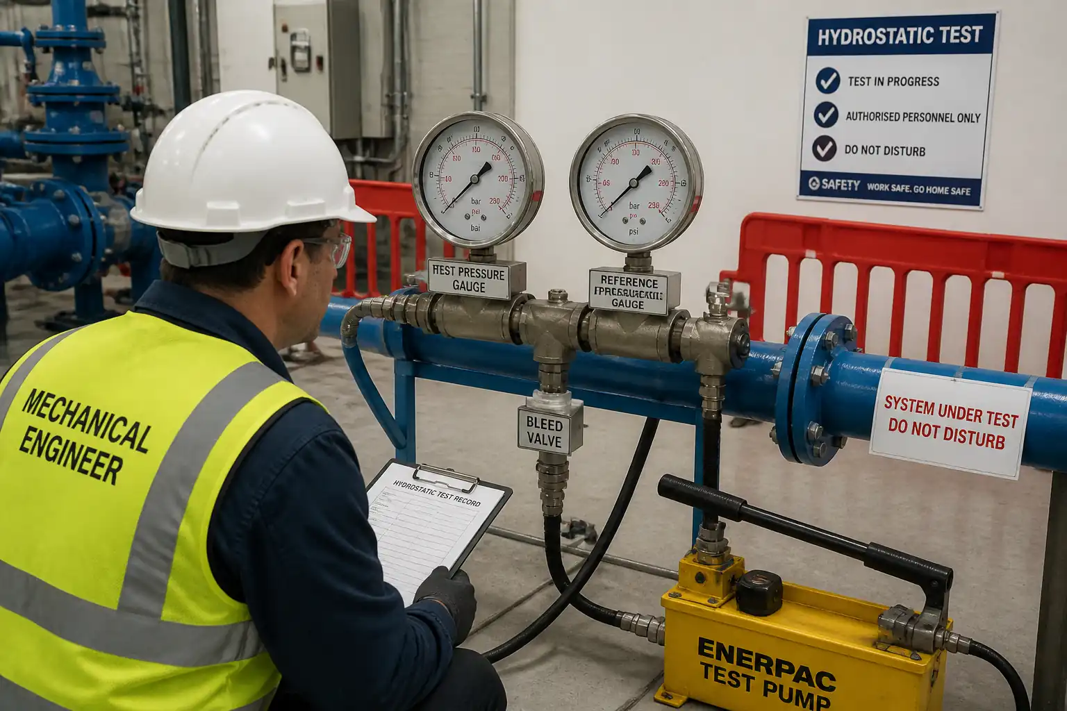
| 2 | Install Gauges and Relief | Install at least two calibrated gauges: one near pump and one at remote/high point; fit relief valve set at 1.1 × test pressure on manifold; fit NRV on pump discharge. | QA/QC / Supervisor | Gauge ID and cal cert check. |
| 3 | Filling and De-Aeration | Close drains; connect fill hose at low point; slowly fill (<1 m/s nominal) while progressively venting all high points until water free of air observed; maintain slightly above atmospheric pressure (~0.2–0.3 bar) to check for immediate leaks. | Supervisor | Visual inspection of vents/air release. |
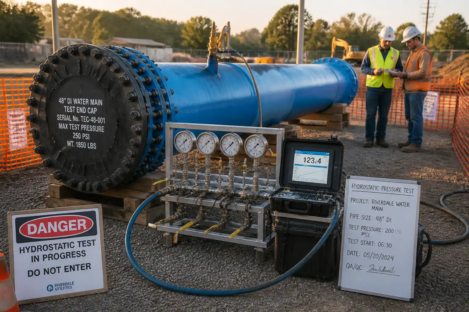
| 4 | Initial Pressurization (Staged) | Increase pressure in increments: 25%, 50%, 75%, 100% of WP; hold 10–15 min at each stage for inspection; then raise to test pressure (Pt = 1.5 × WP [Verify]). | Supervisor / QA/QC | Joint-by-joint walkdown at each stage. |
| 5 | Stabilization Soak | At full test pressure, isolate pump and allow stabilization 30–60 min to accommodate pipe strain and temperature equalization. Top-up if due to temperature drop only. | QA/QC | Temperature recorded at start/end of soak. |
| 6 | Official 24-h Hold and Monitoring | Commence 24-hour hold. Record pressure and temperature hourly at both gauges; if using datalogger, set 5–15 min interval. Investigate any trend beyond expected thermal effects. | QA/QC / Supervisor | Hourly readings; leak patrols. |
| 7 | Leak Rectification (if required) | Depressurize safely; drain local area; repair joint; re-fill, de-air, and re-test from Step 3. Record NCR if repeated failures occur. | Supervisor / QA/QC | Post-repair inspection. |
| 8 | Depressurization and Draining | After successful test, gradually release pressure via low-point drain to containment; prevent splash; open vents to admit air and avoid vacuum; capture and dispose/reuse per environmental plan. | Supervisor / HSE | Drain route/containment check. |
| 9 | Reinstatement | Remove blinds/end caps; reinstall spools; restore valves to design position; remove temporary vents/drains where not permanent; dry and protect system pending flushing/commissioning. | Supervisor | Punch list closeout walkdown. |
| 10 | Documentation and Acceptance | Compile signed ITP checklists, logs, calibration certs, isometrics as tested, and witness forms. Submit test report for approval. | QA/QC Engineer | Document review. |
Health, Safety and Environment (HSE) – Safety Controls
Task-Specific Hazards and Controls
- Hazard: Stored energy and pipe/hoses rupture under pressure.
- Likely consequence: Serious injury from projectile/whip, flooding, structural damage.
- Engineering/procedural control: Pressure-rated hoses with whip-checks; relief valve set to 1.1 × test pressure; staged pressurization; exclusion zone with hard barricades; inspect all connections before each pressure increment; no hot works during test.
- Required PPE: Hard hat, safety goggles/face shield, gloves (cut-resistant), steel-toe boots, hearing protection near pump.
- Collective preventive measure: Barriers and access control; emergency stop and depressurization plan; clear communication (radios) and test leader authority.
-
Inspection/permit/supervision: Permit to Test; pre-use inspection of pump/hoses; competent supervisor present; HSE walkdown.
-
Hazard: Uncontrolled water discharge/flooding.
- Likely consequence: Slip hazards, electrical shock, property damage.
- Engineering/procedural control: Plan drain route; use hoses to containment; isolate nearby electrical; install RCD/ELCB; absorbent barriers.
- PPE: Waterproof boots, gloves.
- Collective: Floor protection and bunds; housekeeping stations.
-
Inspection/permit: Drain procedure approved; electrician sign-off on temporary power.
-
Hazard: Working at height to access high-point vents/gauges.
- Consequence: Falls from height.
- Control: Use certified scaffold or MEWP; 3-point contact; no leaning from ladders; tool lanyards.
- PPE: Full body harness with double lanyard when required; helmet with chin strap.
- Collective: Guardrails/toeboards on platforms.
-
Inspection/permit: Scaffold tag (green); MEWP inspection; work-at-height permit.
-
Hazard: Contact with chemical inhibitors/biocides (if used).
- Consequence: Skin/eye irritation, inhalation hazard.
- Control: Follow SDS; closed dosing system; eyewash nearby; spill kit.
- PPE: Chemical-resistant gloves, goggles/face shield, apron.
- Collective: Ventilation in plantrooms; SDS briefing.
-
Inspection/permit: COSHH assessment; [Verify per project HSE plan and local regulations].
-
Hazard: Noise and vibration from pumps.
- Consequence: Hearing damage, hand–arm vibration.
- Control: Locate pump in ventilated area; anti-vibration pads; limit exposure time.
- PPE: Hearing protection as required by noise survey.
- Collective: Noise signage.
-
Inspection/permit: HSE monitoring if >80 dB(A).
-
Hazard: Confined/poorly ventilated plantrooms.
- Consequence: Heat stress, poor egress, emergency evacuation difficulty.
- Control: Keep exits clear; max occupancy; fans for ventilation.
- PPE: Lightweight PPE; hydration.
- Collective: Spotter at entry.
-
Inspection/permit: Confined space assessment if applicable; PTW.
-
Hazard: Manual handling of blinds/spools.
- Consequence: Musculoskeletal injury, pinch points.
- Control: Team lifts and mechanical aids; pinch-point awareness; gloves.
- PPE: Cut-resistant gloves, safety shoes.
- Collective: Use trolleys/lifters.
- Inspection/permit: Lifting plan for heavy items.
Note: Where exact controls depend on local law or the project HSE plan, apply them and record deviations/approvals. [Verify per project HSE plan and local regulations]
Environmental Controls
Environmental Risk Controls
- Water consumption and discharge
- Control: Estimate volume by section; plan reuse for flushing where permissible; discharge via sediment filter/mesh to prevent debris; sample if required by permit.
-
Acceptance: Discharge quality meets local authority limits for TSS, pH 6–9, temperature within ambient +/− 5 °C [Verify per local regulations].
-
Chemical handling (inhibitors/biocides if dosed)
- Control: Closed-loop dosing, secondary containment for drums; SDS-compliant storage; spill kits; trained personnel.
-
Acceptance: Zero uncontrolled spills; waste disposed via licensed handler.
-
Noise and energy
-
Control: Place pump away from receptors; daytime operation; fuel/electric efficiency consideration; shut down when not needed.
-
Waste management
-
Control: Collect damaged gaskets/consumables; segregate waste; maintain housekeeping; no discharge to storm drains.
-
Records and compliance
- Control: Keep discharge logs, volumes, and any test results; environmental permit/approval attached to test pack where required.
Quality Assurance and Quality Control
QA/QC Controls
- Test Pack Contents: Approved isometric with boundary marked, valve list and positions, WP/test pressure calculation, risk assessment, ITP, hold points, calibration certificates (ISO/IEC 17025 traceable), gauge IDs/locations, checklists, pressure/temperature logs, photos, witness forms.
- Instruments: Gauges accuracy class ≤1% F.S.; range 1.5–2.0 × test pressure; calibration valid; cross-check two gauges; optional digital logger.
- Test Conditions: Water temperature recorded at start/end; ambient conditions noted; soak 30–60 min before official hold.
- Acceptance Criteria (typical – verify per project):
1) No visible leaks, sweating, or permanent deformation.
2) After 24-h hold, pressure drop is within instrument tolerance and corrected for temperature effect; typical target ≤1% of test pressure or within gauge resolution, whichever is greater. [Verify per project specifications]
3) All joints/supports intact; no movement of anchors/restraints beyond design allowances. - Defect Management: If leakage found, depressurize, repair per approved procedure, and re-test full duration unless otherwise approved by Consultant.
- Documentation: All readings logged hourly minimum; any top-ups recorded with time/quantity and reason; final report signed by Contractor and Consultant.
- Traceability: Section ID and drawing references on every log page; instrument serial numbers on each sheet; photos geotagged/time-stamped where possible.
Attachments
- Approved test isometric with boundaries highlighted and unique section ID.
- Pressure test calculation sheet (WP and Pt) signed by responsible engineer.
- Instrument register: gauge IDs, ranges, accuracy, calibration certificates.
- Pre-test checklist and torque record for joints/couplings.
- Permit to Work/Permit to Test and HAZID/RA.
- Stage hold, soak, and 24-h monitoring logs (with temperature records).
- Consultant/Client witness forms and approvals.
- Environmental discharge plan/permit and drain log.
- Photographic record (before pressurization, at Pt, after hold, reinstatement).
This content is a read-only public reference. Download or customize to get an editable version.
ITP preview
The first inspection activities from the linked ITP for Method Statement: Hydrostatic Pressure Testing of Chilled Water (CHW) Piping Networks:
| Activity | Inspection / Test | Acceptance Criteria | Responsibility | Record |
|---|---|---|---|---|
| Review of IFC drawings, specs, and test calculations | Check WP, Pt = 1.5 × WP unless limited by component rating | Documents approved; pressures defined; boundaries identified [Verify per project] | QA/QC Engineer / Mechanical Engineer | Approved Test Pack |
| Calibration verification of gauges and thermometer | Validity, range, and accuracy class | ISO/IEC 17025 traceability; accuracy ≤1% F.S.; range 1.5–2.0 × Pt | QA/QC Engineer | Calibration Certificates |
| Pre-test installation inspection (vents, drains, supports, isolation) | Walkdown with checklist | All high points vented; low points drainable; equipment isolated; supports complete | Mechanical Engineer / Supervisor | Pre-Test Checklist & Photos |
Showing 3 of 9 inspection activities. View full ITP →
Related Inspection and Test Plan
An Inspection and Test Plan (ITP) is available for Method Statement: Hydrostatic Pressure Testing of Chilled Water (CHW) Piping Networks. The ITP defines the inspection activities, acceptance criteria, hold and witness points, responsible parties, and records required to verify the work described in this method statement.
View the Method Statement: Hydrostatic Pressure Testing of Chilled Water (CHW) Piping Networks ITP →Frequently asked questions
Continue with related Quollnet resources connected to this method statement.