
Method Statement: Installation of Carbon Steel Chilled Water Piping with Welded Joints – Method Statement
AI-assisted method statement with matching ITP, PDF download, and Excel export.
More than a static template
Unlike a downloadable Word or PDF template, this method statement is an AI-assisted editable starting point connected directly to a matching Inspection and Test Plan. Every section is structured, project-adaptable, and ready to export.
- AI-assisted drafting — Customize every section with AI for your specific project scope.
- Linked ITP — A matching inspection and test plan is generated alongside the method statement.
- Multiple export formats — Download as a formatted PDF or editable Excel spreadsheet.
- Editable starting point, not a final document — Review, verify, and adjust all content against your project requirements before use.
Static template vs. Quollnet workflow
| Feature | Static template | Quollnet |
|---|---|---|
| Project-specific content | Manual fill-in required | AI-assisted customization |
| Linked ITP | Separate document, no link | Matching ITP included |
| Export formats | Usually PDF only | PDF and Excel |
| Structured sections | Free-form layout | 13 standardized sections |
| Saved to your account | Local file only | Cloud-saved, reusable |
| Content accuracy | You verify everything | AI-assisted, you still verify |
| Cost | Often free but time-intensive | Free to customize and download |
What you can customize
When you save this method statement to your account, every section becomes editable. The following 13 sections are included:
- Scope — Defines the activity and its boundaries.
- References — Standards, specifications, and drawings.
- Responsibilities — Roles and accountabilities.
- Resources — Labour, plant, and equipment summary.
- Materials — Materials and compliance requirements.
- Equipment — Tools and equipment details.
- Prerequisites — Hold points and pre-conditions.
- Method sequence — Step-by-step construction sequence.
- Safety controls — HSE risk controls and PPE.
- Environmental controls — Environmental mitigation measures.
- QA/QC — Quality inspection and test requirements.
- ITP — Inspection and Test Plan table (has its own page).
- Attachments — Referenced drawings and documentation.
Why this method statement is used
This method statement is used to define and communicate the approved procedure for carrying out method statement: installation of carbon steel chilled water piping with welded joints on site. It ensures the work is planned in advance, the correct resources and controls are in place, and all personnel understand responsibilities, sequence, quality requirements, and safety controls before work begins. It aligns site execution with the documented scope and acceptance expectations.
Who uses this method statement
This method statement is used by contractors, site supervisors, project engineers, QA/QC engineers, HSE officers, consultants, and client representatives. It serves as a shared reference for planning, execution, supervision, inspection, and approval of the activity on site.
When it is prepared and submitted
The method statement is prepared before the work activity starts and submitted as part of the pre-construction documentation package for review and approval.
Who reviews or approves it
The method statement is usually submitted to the client representative, consultant, resident engineer, or project management consultant for review and approval before the work commences.
Important approval note
This method statement is an AI-assisted editable starting point, not a pre-approved document. Before use on any project, all content must be reviewed and approved by the relevant parties (superintendent, principal contractor, or client representative) in accordance with your contract and project quality plan.
For example: if your specification requires a departure from a referenced standard, that departure must be documented and approved separately — this method statement will not capture that automatically. Always verify against your applicable drawings, specifications, and regulatory requirements.
Method statement content
Scope
Overview
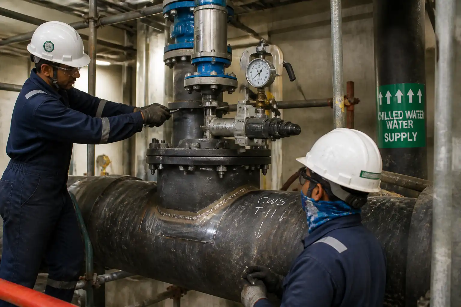
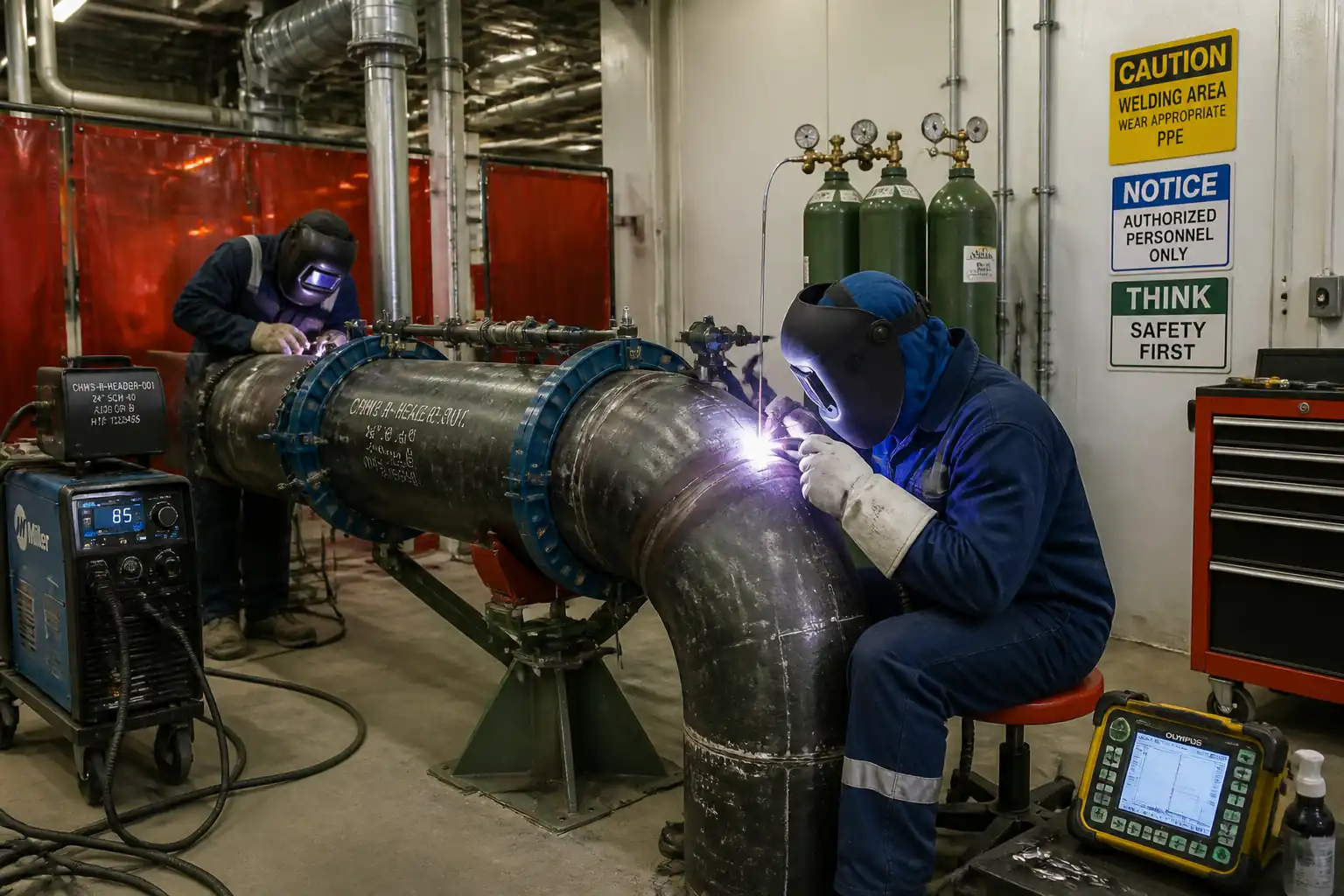
This method statement covers the complete installation of carbon steel chilled water (CHW) piping using welded butt joints and required fittings in plant rooms and services corridors. The scope includes material verification, pipe cutting, beveling, fit-up, welding (root and multi-pass), slag removal, weld inspection/NDT, hydrostatic testing, painting/touch-up at weld areas, and documentation.
Included Works
- Verification of IFC isometrics, line list, P&IDs, WPS/PQR, and welder qualifications.
- Handling, storage, and identification of pipes, fittings, and welding consumables.
- Pipe cutting and end preparation to ASME B16.25 or ISO equivalent.
- Alignment, fit-up, tack welding, and preheat/interpass control per approved WPS.
- Root pass inspection, multi-pass welding, interpass cleaning, and cap finishing.
- NDT coordination (VT 100%; RT/UT/MT extent per project specifications).
- Hydrostatic pressure testing, drying/draining, and reinstatement.
- Coating/painting touch-up at welded areas and final marking.
- As-built documentation, weld maps, and test records.
Exclusions
- Thermal insulation and jacketing.
- Chemical cleaning/flushing and water treatment beyond hydrostatic test water quality control (unless noted in project specs).
- Valve internals setting and actuator calibration.
Typical Limits
- Piping size: DN25–DN600 [Verify per project].
- Material: Carbon steel (e.g., ASTM A53/A106 Gr B or EN 10216/10255) [Verify per project].
- Design code: ASME B31.9 (Building Services Piping) or ASME B31.3 (if specified) [Verify per project].
References
| Document Type | Reference / Number | Revision | Notes |
|---|---|---|---|
| Code | ASME B31.9 / ASME B31.3 | Latest | |
| Code | ASME Section IX or ISO 15614-1 (WPS), ISO 9606-1 (Welder) [Verify per project] | Latest | |
| Standard | ASME B16.25 | Latest | |
| Standard | ASTM A53/A106; ASME B16.9 (fittings); ASME B16.5 (flanges) or EN/BS equivalents [Verify per project] | Latest | |
| Standard | ASME Section V or ISO 17635/17637(VT)/17638(MT)/17640(UT)/17636(RT) [Verify per project] | Latest | |
| Standard | ASME B31.9/B31.3 acceptance criteria or ISO 5817 Level C [Verify per project] | Latest | |
| Standard | ISO 8501-1 (surface prep), ISO 12944 (protective paint) [Verify per project] | Latest | |
| Code | ASME B31.9 (test pressure typically 1.5 × design) [Verify per project] | Latest |
Responsibilities
| Role | Responsibility | Name / Party |
|---|---|---|
| PM | Project Manager | Contractor |
| CM | Construction Manager | Contractor |
| Engineer | Site Engineer | Contractor |
| Welding Engineer | Welding Engineer | Contractor |
| QA/QC | QA/QC | Contractor |
| HSE | HSE | Contractor |
| NDT | NDT Subcontractor | Approved Lab |
| Supervisor | Piping Supervisor | Contractor |
Resources
| Resource Type | Description | Quantity | Remarks |
|---|---|---|---|
| Manpower | ASME IX or ISO 9606-1 certified for relevant positions (1G–6G) | 4–8 | Maintain continuity logs |
| Manpower | Experience with CS piping fit-up and alignment | 4–8 | |
| Manpower | Certified rigging and signaling | 2–4 | |
| Manpower | Level II minimum for MT/UT/RT | As needed |
Materials
| Material | Specification / Grade | Quantity | Remarks |
|---|---|---|---|
| Carbon Steel | Size: DN25–DN600; Sch 40/80 [Verify] | As per BOQ | ASTM A53/A106 Gr B or EN 10216/10255 [Verify] |
| CS | ASME B16.9 | As per BOQ | |
| CS | ASME B16.5, Class 150/300 [Verify] | As per BOQ | |
| E7018, E6010, ER70S-2/6 | AWS A5.1/A5.18 | As required | Low hydrogen control required |
| Argon | 99.99% purity [Verify] | As required | |
| Epoxy/alkyd system | ISO 12944 compatible [Verify] | As required | |
| Compressed fiber/EPDM; ASTM A193/A194 bolts [Verify] | As required |
Equipment
| Equipment | Capacity / Type | Quantity | Inspection Required |
|---|---|---|---|
| Welding Power Source | Up to 300 A | 4–8 | Yes |
| Rod Oven | 120–400°C | 1 store + 2 portable | Yes |
| Cold Cutter/Beveler | DN25–DN600 | As required | Yes |
| Clamps & Gauges | As required | Yes | |
| 1–3 t chain blocks | Up to 3 t | As required | Yes |
| Measuring tools | Sets | Yes | |
| NDT instruments | As required | Yes | |
| Hydro pump & gauges | Up to required test P | 1 set/test pack | Yes |
Prerequisites
- Approved method statement, risk assessment, and ITP.
- IFC isometrics, P&IDs, support drawings, and weld maps available on site.
- Approved material submittals (pipes, fittings, consumables) and MTCs.
- Approved WPS/PQR; welder qualifications (WPQ) valid for position/thickness/material group; continuity log updated.
- Calibrations valid for welding machines, gauges, UT/MT/RT equipment, pressure gauges.
- PTW issued for hot works, lifting, confined space (if any), and radiography [Verify per project HSE plan and local regulations].
- Work area cleared, scaffold/MEWP inspected, lifting plan approved where applicable.
- Temporary supports/hangers planned to avoid weld distortion and overloading.
- NDT subcontractor availability and hold/witness points agreed with Consultant.
- Hydrotest test packs prepared: line list, test boundaries, blinds, vents, test medium, acceptance criteria.
- Fire watch and firefighting equipment available for all hot works.
Method Sequence
| Step | Activity | Description | Responsibility | Inspection / Hold Point |
|---|---|---|---|---|
| 1 | Material Receipt & Verification | Receive and inspect pipes/fittings/consumables. Check MTCs, heat numbers, size/schedule, damages, coating condition. Segregate by line class. | QA/QC, Storekeeper | Visual; document check |
| 2 | WPS/WPQ Verification | Confirm approved WPS/PQR covers material, thickness, position, process (GTAW/SMAW). Verify welder qualifications current and within scope. | Welding Engineer, QA/QC | Document check |
| 3 | Cutting & End Preparation | Measure and mark as per spool/iso. Use cold cutting. Bevel ends to ASME B16.25: 37.5° ±2.5°; root face 1.6 mm ±0.8 mm; root gap at fit-up 3.0 mm ±1.0 mm [Verify per WPS]. Deburr and clean to bare metal 25 mm from edge. | Pipe Fitter | Dimensional check |
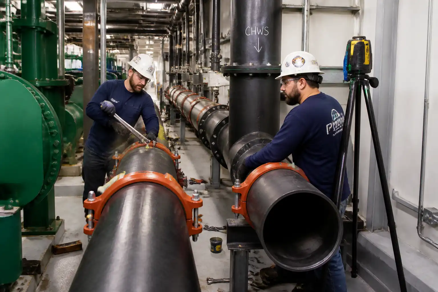
| 4 | Fit-Up & Alignment | Set with internal/external clamps. Verify root gap and hi-lo using gauge. Use spacers/dogs if required. Tack weld using qualified process/filler; grind tacks if they remain in weld. Install temporary supports to maintain alignment. | Pipe Fitter, Welder | Visual/dimensional |
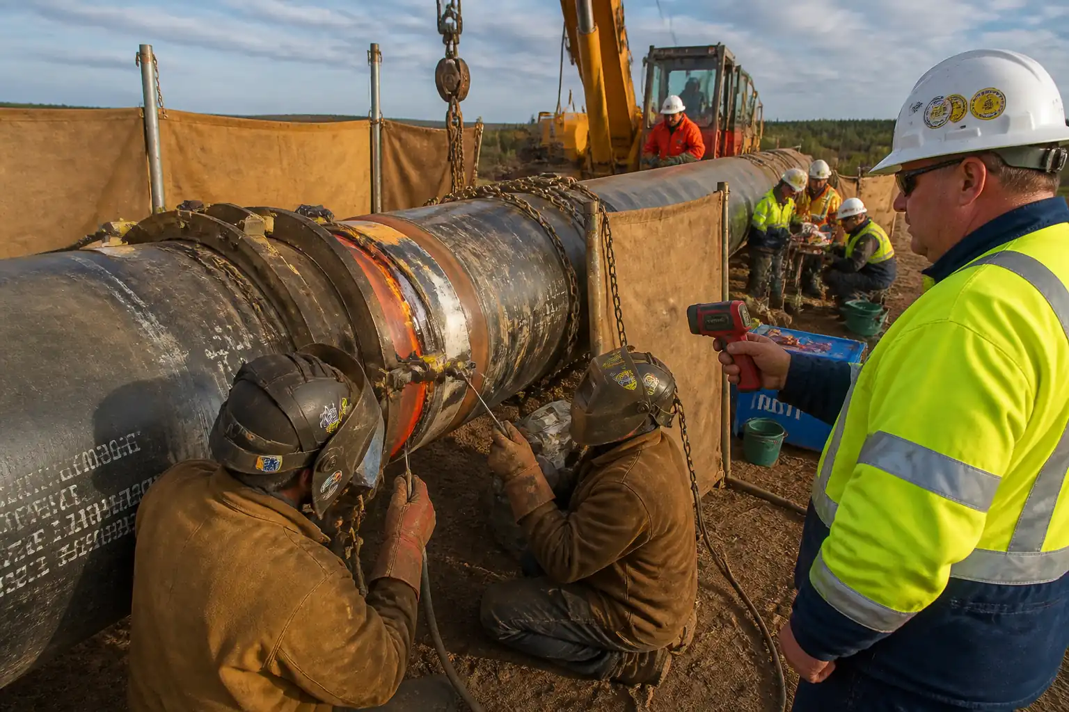
| 5 | Preheat & Interpass Control | Preheat per WPS using temp sticks/IR thermometer. Typical preheat: 50–100°C depending on thickness/CE [Verify per WPS]. Maintain interpass ≤250°C [Verify per WPS]. Shield joint from drafts. | Welder, Welding Eng. | Measurement |
| 6 | Root Pass Welding | Execute root using GTAW (ER70S-2/6) or SMAW (E6010 where permitted). Control heat input/travel as per WPS. Clean and grind root as needed to sound metal. | Welder | In-process |
| 7 | Root Pass VT (and MT if specified) | After cleaning, perform VT of root (internal via borescope if accessible). MT may be required for accessible external surfaces per ITP. | QA/QC, NDT | VT/MT |
| 8 | Hot Pass, Fill & Cap | Deposit hot pass and subsequent layers (SMAW E7018 or GTAW) with interpass cleaning. Use stringer or weave per WPS. Finish cap slightly convex 1–3 mm reinforcement. | Welder | In-process |
| 9 | Interpass Cleaning & Slag Removal | Remove slag and spatter thoroughly between passes using chipping and wire brush. Clean with solvent only if approved and fully evaporated. | Welder | Visual |
| 10 | Final Visual & Dimensional Inspection | VT after cap: check profile, reinforcement, undercut, arc strikes, dimensional compliance to isos/spools, support locations and clearances. | QA/QC, Site Eng. | VT/dimensional |
| 11 | NDT (RT/UT/MT as per ITP) | Carry out NDT extent per project (e.g., 10% RT/UT of butt welds minimum, more for critical lines) [Verify]. Coordinate radiography safety zones or UT access. | NDT Technician, QA/QC | RT/UT/MT |
| 12 | Repair (if required) | Mark/plan repair, remove defect by grinding/gouging, re-weld per WPS. Re-inspect same method and extent as original or as ITP requires. | Welder, QA/QC | VT + NDT |
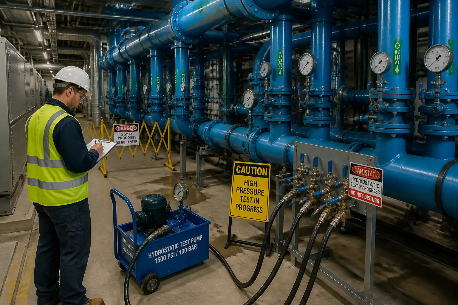
| 13 | Hydrostatic Pressure Test | Prepare test pack; install blinds; fill with clean water (with inhibitor if specified); vent air; pressurize to 1.5 × design pressure [Verify]; hold 30–60 min [Verify]; examine for leaks/pressure drop. | QA/QC, Site Eng. | Witness |
| 14 | Draining, Drying & Reinstatement | Depressurize, drain to approved point, blow out with clean dry air where required, remove blinds, reinstall components, restore vents/drains. | Site Eng., Supervisor | Visual |
| 15 | Coating/Paint Touch-Up at Welds | Prepare surface (St 2/3), apply primer and topcoat per TDS to specified DFT. Mark line number, flow, and identification. | Painting Supervisor | DFT checks |
| 16 | Documentation & Handover | Compile weld map, material traceability, NDT, hydrotest, repairs, painting, and as-built marked isometrics; submit dossier. | QA/QC | Review |
Safety Controls
For each significant hazard, the following items are defined: hazard, likely consequence, engineering/procedural control, required PPE, collective preventive measure, and inspection/permit/supervision requirement.
1) Hot works (welding, grinding)
- Consequence: Burns, fire, eye injury.
- Controls: Hot work PTW; remove combustibles 10 m; non-sparking mats; fire blankets; dedicated fire watch with extinguisher and charged hose.
- PPE: FR coveralls, welding helmet with correct shade, leather gloves/apron, safety boots, safety glasses, ear protection.
- Collective measures: Welding screens to protect others; spark containment.
- Inspection/Permit/Supervision: PTW; daily fire watch log; HSE inspection before start and after shift.
2) Fumes and gases (welding smoke, argon)
- Consequence: Respiratory irritation, asphyxiation in poorly ventilated/confined spaces.
- Controls: Local exhaust ventilation; avoid shielding gas accumulation; continuous gas monitoring in confined spaces.
- PPE: Respiratory protection P2/P3 if ventilation inadequate; standard PPE as above.
- Collective measures: Mechanical ventilation/air movers.
- Inspection/Permit/Supervision: Confined space permit; atmospheric testing records; HSE oversight.
3) Radiography (if RT used)
- Consequence: Radiation exposure.
- Controls: Prefer UT where feasible. If RT required, restrict area with barriers 25 m or as calculated; warning lights/signage; licensed radiography team.
- PPE: Dosimeters for RT crew; standard PPE for others outside exclusion zone.
- Collective measures: Controlled access and spotter.
- Inspection/Permit/Supervision: RT permit; survey meter readings; RPO supervision; records retained.
4) Lifting and handling of pipes/spools
- Consequence: Crush injuries, dropped loads.
- Controls: Approved lifting plan, certified gear, tag lines, exclusion zones.
- PPE: Helmet with chin strap, gloves, boots, hi-vis.
- Collective measures: Banksman control; barricades.
- Inspection/Permit/Supervision: Pre-lift checklist; gear certificates; competent rigger/banksman.
5) Grinding/cutting operations
- Consequence: Flying particles, noise, hand injuries.
- Controls: Guards in place; correct discs; two-handed operation; sparks directed away.
- PPE: Face shield over safety glasses, gloves, hearing protection.
- Collective measures: Grinding booths/screens.
- Inspection/Permit/Supervision: Tool pre-use checks; HSE spot checks.
6) Pressure testing
- Consequence: Component rupture, fluid injection injury.
- Controls: Test boundaries barricaded; pressurize gradually; stand clear; use calibrated gauges; relief valve fitted to pump.
- PPE: Face shield, gloves, boots.
- Collective measures: Exclusion zone; signage.
- Inspection/Permit/Supervision: Test permit; QA/QC witness; Supervisor present.
7) Electrical hazards (welding sets)
- Consequence: Shock, arc flash.
- Controls: PAT-tested equipment; dry leads; intact insulation; isolation when servicing; 30 mA RCD.
- PPE: Dry gloves, FR clothing, dielectric boots where needed.
- Collective measures: Cable management to avoid water/traffic.
- Inspection/Permit/Supervision: Electrical inspection log; competent electrician.
8) Working at height (pipe racks/MEWPs)
- Consequence: Falls.
- Controls: Scaffolds tagged “green”; MEWP harness/anchor; 3-point contact; tools tethered.
- PPE: Full body harness with lanyard; helmet with chin strap.
- Collective measures: Guardrails; toe boards.
- Inspection/Permit/Supervision: Scaffold inspection tags; MEWP inspection; PTW if required.
9) Heat stress and burns
- Consequence: Dehydration, heat-related illness.
- Controls: Work-rest cycles; hydration; shade; handle hot workpieces with tongs.
- PPE: Heat-resistant gloves, FR clothing.
- Collective measures: Cooling fans; shaded rest area.
- Inspection/Permit/Supervision: HSE monitoring; first aid availability.
10) Noise and illumination
- Consequence: Hearing loss; poor visibility leading to incidents.
- Controls: Hearing protection zones; task lighting ≥200 lux at weld area.
- PPE: Earplugs/earmuffs; safety glasses.
- Collective measures: Light towers; signage.
- Inspection/Permit/Supervision: Noise survey (if required); lighting checks.
Note: Where exact controls depend on local law or project HSE plan, verify per project HSE plan and local regulations.
Environmental Controls
- Welding fumes and dust: Use LEV; select low-fume electrodes; avoid excessive grinding. Maintain air quality below occupational limits [Verify per local regs].
- Electrode stubs and slag: Collect in designated metal bins; dispose as non-hazardous waste unless contaminated; record quantities.
- Solvent use and paint touch-up: Use low-VOC where possible; prevent spills; secondary containment for cans; follow SDS; segregate hazardous waste.
- Hydrotest water: Use clean water; add corrosion inhibitor only if specified; discharge to approved drainage after turbidity/pH check and filtration as needed [Verify per permit].
- NDT chemicals (MT): Use aerosol catch mats; prevent overspray; collect wipes as hazardous waste.
- Noise and light spill: Use acoustic screens and welding curtains; limit work hours per permit.
- Energy and gas cylinders: Close valves when not in use; store upright, segregate full/empty; leak test with approved solution.
- Housekeeping: Keep walkways clear; immediate cleanup of spatter and metal offcuts to prevent contamination of drains.
- Spill response: Spill kits at workface; train crew; report and document incidents.
- Environmental monitoring: Maintain waste transfer notes, water discharge logs, and monthly environmental checklist.
QA / QC
General
- Applicable codes: ASME B31.9 (or B31.3 if specified), ASME Section IX/ISO 15614-1/ISO 9606-1 for welding qualifications, ASME Section V/ISO 17635 series for NDT [Verify per project].
- Hold/witness points as per ITP; no work to proceed past hold points without approval signatures.
Welding Controls
- WPS/PQR: Use only Client-approved WPSs; parameters recorded on weld logs (current, voltage, travel speed or heat input range) [Per WPS].
- Preheat/interpass: Measure using temp sticks or IR thermometer; typical preheat 50–100°C; interpass ≤250°C unless WPS states otherwise [Verify].
- Joint prep: Bevel angle 37.5° ±2.5°, root face ~1.6 mm ±0.8 mm, root gap 3.0 mm ±1.0 mm unless WPS differs.
- Consumables: Low hydrogen control for E7018: baking as per manufacturer; holding oven 120–150°C; issue in heated quivers; record batch/heat and welder ID.
- Welder continuity: Update monthly; suspension after lapse per ASME IX/Project requirement.
- Arc strikes: Prohibited on base metal outside groove; if present, grind and MT check.
Inspection & NDT
- VT: 100% of welds per ISO 17637 immediately after cleaning each critical stage (root and final).
- NDT extent: Typical baseline 10% RT or UT of full penetration butt welds; 100% for critical joints/tie-ins as specified; MT on surface where required [Verify per ITP/spec].
- Acceptance criteria: ASME B31.9/B31.3 or ISO 5817 Level C for imperfections [Verify per project].
- Repairs: Same WPS; record defect type/location; NDT re-test same method and extent.
Pressure Testing
- Test pressure: 1.5 × design pressure, hold 30–60 minutes [Verify per project]; two calibrated gauges in 1.5–4 × test pressure range; gauge agreement within 5%.
- Acceptance: No leakage/pressure drop; joints dry and tight; document vent/drain points and reinstatement.
Records
- Weld map and numbering; welder IDs; heat numbers per spool; material receiving inspection; fit-up and VT reports; NDT reports and films; repair logs; hydrotest pack (gauges certs, permits, sketches); coating/DFT logs; calibration certificates; as-built isometrics; NCRs and close-outs.
Attachments
- Approved WPS/PQR and register.
- Welder qualifications (WPQ) and continuity logs.
- IFC isometrics, P&IDs, line list, and weld map.
- Material approvals (MAS), MTCs, consumable COCs.
- Calibration certificates (welding sets, gauges, NDT equipment, DFT meters).
- ITP and signed ITRs at each stage.
- NDT procedures and reports (VT/MT/UT/RT) including films and interpretations.
- Hydrostatic test packs (sketches, gauge certs, permits, reports).
- Coating system TDS/SDS and DFT reports.
- NCRs, corrective actions, concessions (if any).
- As-built drawings and final turnover dossier.
This content is a read-only public reference. Download or customize to get an editable version.
ITP preview
The first inspection activities from the linked ITP for Method Statement: Installation of Carbon Steel Chilled Water Piping with Welded Joints:
| Activity | Inspection / Test | Acceptance Criteria | Responsibility | Record |
|---|---|---|---|---|
| Material receipt and identification | Verify grade, size, MTCs, heat numbers | Correct material per approved submittals; traceable; free from damage | QA/QC, Consultant | Material receiving report, MTCs |
| WPS/PQR/WPQ verification | Document review | Approved and valid for process, position, thickness, material | Welding Eng., QA/QC, Consultant | Approved WPS/PQR/WPQ copies |
| Joint preparation and fit-up | Bevel angle/land; root gap; hi-lo check | As per WPS/ASME B16.25; hi-lo ≤10% WT (max 1.5 mm); root gap 3±1 mm | QA/QC, Consultant | Fit-up report with photos |
Showing 3 of 10 inspection activities. View full ITP →
Related Inspection and Test Plan
An Inspection and Test Plan (ITP) is available for Method Statement: Installation of Carbon Steel Chilled Water Piping with Welded Joints. The ITP defines the inspection activities, acceptance criteria, hold and witness points, responsible parties, and records required to verify the work described in this method statement.
View the Method Statement: Installation of Carbon Steel Chilled Water Piping with Welded Joints ITP →Frequently asked questions
Continue with related Quollnet resources connected to this method statement.