Method Statement – Oil & Gas Pipeline Welding Works (WPS, Welder Qualification, Fit-Up, Preheat, Welding, NDT, Repairs, Traceability) – Method Statement
AI-assisted method statement with matching ITP, PDF download, and Excel export.
More than a static template
Unlike a downloadable Word or PDF template, this method statement is an AI-assisted editable starting point connected directly to a matching Inspection and Test Plan. Every section is structured, project-adaptable, and ready to export.
- AI-assisted drafting — Customize every section with AI for your specific project scope.
- Linked ITP — A matching inspection and test plan is generated alongside the method statement.
- Multiple export formats — Download as a formatted PDF or editable Excel spreadsheet.
- Editable starting point, not a final document — Review, verify, and adjust all content against your project requirements before use.
Static template vs. Quollnet workflow
| Feature | Static template | Quollnet |
|---|---|---|
| Project-specific content | Manual fill-in required | AI-assisted customization |
| Linked ITP | Separate document, no link | Matching ITP included |
| Export formats | Usually PDF only | PDF and Excel |
| Structured sections | Free-form layout | 13 standardized sections |
| Saved to your account | Local file only | Cloud-saved, reusable |
| Content accuracy | You verify everything | AI-assisted, you still verify |
| Cost | Often free but time-intensive | Free to customize and download |
What you can customize
When you save this method statement to your account, every section becomes editable. The following 13 sections are included:
- Scope — Defines the activity and its boundaries.
- References — Standards, specifications, and drawings.
- Responsibilities — Roles and accountabilities.
- Resources — Labour, plant, and equipment summary.
- Materials — Materials and compliance requirements.
- Equipment — Tools and equipment details.
- Prerequisites — Hold points and pre-conditions.
- Method sequence — Step-by-step construction sequence.
- Safety controls — HSE risk controls and PPE.
- Environmental controls — Environmental mitigation measures.
- QA/QC — Quality inspection and test requirements.
- ITP — Inspection and Test Plan table (has its own page).
- Attachments — Referenced drawings and documentation.
Why this method statement is used
This method statement is used to define and communicate the approved procedure for carrying out method statement – oil & gas pipeline welding works (wps, welder qualification, fit-up, preheat, welding, ndt, repairs, traceability) on site. It ensures the work is planned in advance, the correct resources and controls are in place, and all personnel understand responsibilities, sequence, quality requirements, and safety controls before work begins. It aligns site execution with the documented scope and acceptance expectations.
Who uses this method statement
This method statement is used by contractors, site supervisors, project engineers, QA/QC engineers, HSE officers, consultants, and client representatives. It serves as a shared reference for planning, execution, supervision, inspection, and approval of the activity on site.
When it is prepared and submitted
The method statement is prepared before the work activity starts and submitted as part of the pre-construction documentation package for review and approval.
Who reviews or approves it
The method statement is usually submitted to the client representative, consultant, resident engineer, or project management consultant for review and approval before the work commences.
Important approval note
This method statement is an AI-assisted editable starting point, not a pre-approved document. Before use on any project, all content must be reviewed and approved by the relevant parties (superintendent, principal contractor, or client representative) in accordance with your contract and project quality plan.
For example: if your specification requires a departure from a referenced standard, that departure must be documented and approved separately — this method statement will not capture that automatically. Always verify against your applicable drawings, specifications, and regulatory requirements.
Method statement content
Scope
Overview
This method statement defines the procedures and controls for onshore oil and gas carbon steel pipeline girth welding from fit-up to final acceptance, including:
- WPS/PQR approval and welder qualification control
- Joint preparation, line-up and fit-up
- Preheat, interpass, and environmental controls
- Welding execution and sequence (mainline and tie-ins)
- Welding consumable handling, storage, and traceability
- Weld numbering, mapping, and documentation
- Coordination and execution of NDT (VT, RT/AUT, MT/PT, UT as applicable)
- Repair welding (defect removal and rewelding)
- QA/QC hold and witness points, records, and acceptance for release to coating
Inclusions
- Mainline girth welds, tie-in welds, and repair welds on API 5L line pipe
- Associated temporary works (line-up clamps, welding shelters, preheat equipment)
- Integration with NDT subcontractors and coating teams for release sequencing
Exclusions
- Station/piping shop fabrications beyond right-of-way scope
- Field joint coating application methods (addressed in separate method statement)
- Hydrostatic testing and commissioning (separate procedures)
Constraints/Assumptions
- Base materials: Carbon-manganese pipeline steels (e.g., API 5L Grades X42–X70) [Verify per project specifications]
- Welding processes: SMAW, GMAW/FCAW, GTAW for root (if specified), and mechanized welding where applicable [Verify per WPS]
- Extent of NDT: Typically 100% RT or AUT for mainline girth welds; tie-in extent per project specification [Verify per project specifications]
References
| Document Type | Reference / Number | Revision | Notes |
|---|---|---|---|
| Standard | API Std 1104 | Primary reference for WPS/WPQT, welding, and acceptance for pipelines [Verify project specs] | |
| Code | ASME B31.4 | If applicable to liquids [Verify per project] | |
| Code | ASME B31.8 | If applicable to gas [Verify per project] | |
| Code | ASME Section IX | Use only if project specifies ASME IX for PQR/WQT [Verify] | |
| Standard | ISO 9606-1 | If project governed by ISO system [Verify] | |
| Standard | ISO 3834 | Quality system for welding activities | |
| Standard | ISO 17637 (or API 1104 visual criteria) | Use acceptance per API 1104 unless project calls ISO/EN | |
| Standard | ISO 17636 / API 1104 | Technique per ISO or ASME V; acceptance per API 1104 [Verify] | |
| Standard | ISO 17640, ISO 10863, ISO 11666 | Acceptance levels per API 1104 Annex or project [Verify] | |
| Standard | ASTM E1444 (MT), ASTM E165 (PT) | Personnel per SNT-TC-1A or ISO 9712 [Verify] | |
| Standard | AWS A5.x series / ISO 2560 / ISO 14341 | Select per WPS and base metal grade | |
| Standard | SSPC-SP1 / ASTM D4285 | Oil/grease removal and compressed air cleanliness |
Responsibilities
| Role | Responsibility | Name / Party |
|---|---|---|
| Construction Manager | Construction Manager | Contractor |
| Welding Engineer | Welding Engineer | Contractor |
| Welding Supervisor | Welding Supervisor | Contractor |
| QC Inspector | QC Inspector (CSWIP/ISO 9712 visual) | Contractor |
| NDT Level II/III | NDT Contractor | Subcontractor |
| HSE Officer | HSE Officer | Contractor |
| Engineer/Client Rep | Client/Engineer Representative | Client/Engineer |
Resources
| Resource Type | Description | Quantity | Remarks |
|---|---|---|---|
| Personnel | Lead welder + assistant + grinder man per station | As per shift plan | |
| Personnel | Line-up clamp operator, pipe fitters | As required | |
| Personnel | QC Inspector (VT), NDT Level II, Level III (as needed) | Per ITP coverage | |
| Personnel | HSE Officer and fire watch during hot works | Per crew/location |
Materials
| Material | Specification / Grade | Quantity | Remarks |
|---|---|---|---|
| Carbon steel pipe | API 5L PSL2 [Verify] | As per BOQ | |
| Welding electrodes/wires | Per approved WPS | Per production | |
| Welding electrodes | Per approved WPS | Per production | |
| Wire & gas | Per WPS | Per production | |
| Solvents | Low-residue, approved | As required | |
| NDT supplies | Per NDT procedure | As required |
Equipment
| Equipment | Capacity / Type | Quantity | Inspection Required |
|---|---|---|---|
| SMAW/GMAW/FCAW machines | Duty cycle ≥ 300 A continuous [Verify] | Per welding station | |
| Clamps | Per pipe OD [Verify] | As needed | |
| Lifting equipment | SWL adequate for pipe sections | Per spread | |
| Preheat units | Achieve 75–150°C [Verify] | Per weld | |
| Ovens | Holding 100–150°C; rebake 300–350°C [Verify] | Workshop + portable | |
| Bevellers/Grinders | As required | ||
| Measuring devices | Per QC/welding crew |
Prerequisites
- IFC drawings, approved weld joint details, and latest revision of this method statement available at site.
- Approved WPS and supporting PQRs specific to pipe grade, wall thickness, and position; NDT and acceptance levels defined.
- Welders qualified to API 1104 (or ASME IX/ISO 9606-1 if specified) for each process/position; current continuity logs maintained.
- Approved ITP with identified Hold/Witness/Surveillance points; roles and notifications defined.
- Consumable batch certificates available; ovens commissioned and calibrated; exposure limits posted at point of issue.
- Pre-job briefing/toolbox talk conducted; JSA completed; permits to work (hot work, excavation if applicable) in place [Verify per project HSE plan and local regulations].
- Equipment calibration certificates valid; volt/amp meters, thermometers, dew point meter checked.
- NDT contractor procedures approved; radiography safety plan and exclusion zones established (if RT used).
- Environmental controls organized: wind shields, welding shelters, drip trays, fire extinguishers, spill kits.
- Weather constraints understood: no welding when base metal temperature is below 0°C without qualified preheat plan; surface temperature at least 3°C above dew point; wind speed controls per WPS [Verify per project specifications].
- Pipe support/line-up plan established to prevent ovality and stress during welding; internal clamp availability confirmed.
- Weld numbering sequence and weld mapping template prepared; weld traceability pack assembled.
Method Sequence
| Step | Activity | Description | Responsibility | Inspection / Hold Point |
|---|---|---|---|---|
| 1 | Material verification and joint preparation | Verify pipe heat numbers, grade, wall thickness, bevel angle (typically 30°±5°), land (1.6±0.8 mm), and cleanliness (SSPC-SP1). Remove burrs/laminations; check ovality within project tolerance [Verify]. | QC Inspector / Welding Supervisor | Material and bevel check |
| 2 | Fit-up and alignment | Position pipes on rollers; insert internal line-up clamp; set root opening typically 2.0–3.0 mm [Verify]; control high–low (internal misalignment) ≤1.6 mm [Verify]; ensure Hi-Lo measured at 4 quadrants. | Fitters / Welding Supervisor | Fit-up inspection |
| 3 | Preheat and environmental check | Measure ambient, surface, and dew point. Preheat both pipe bevels and 75 mm each side to the WPS min (typ. 75–150°C) and ensure interpass max (typ. 230–250°C) not exceeded. Shield from wind; maintain surface temp ≥3°C above dew point. | Welder / QC Inspector | Temperature verification |
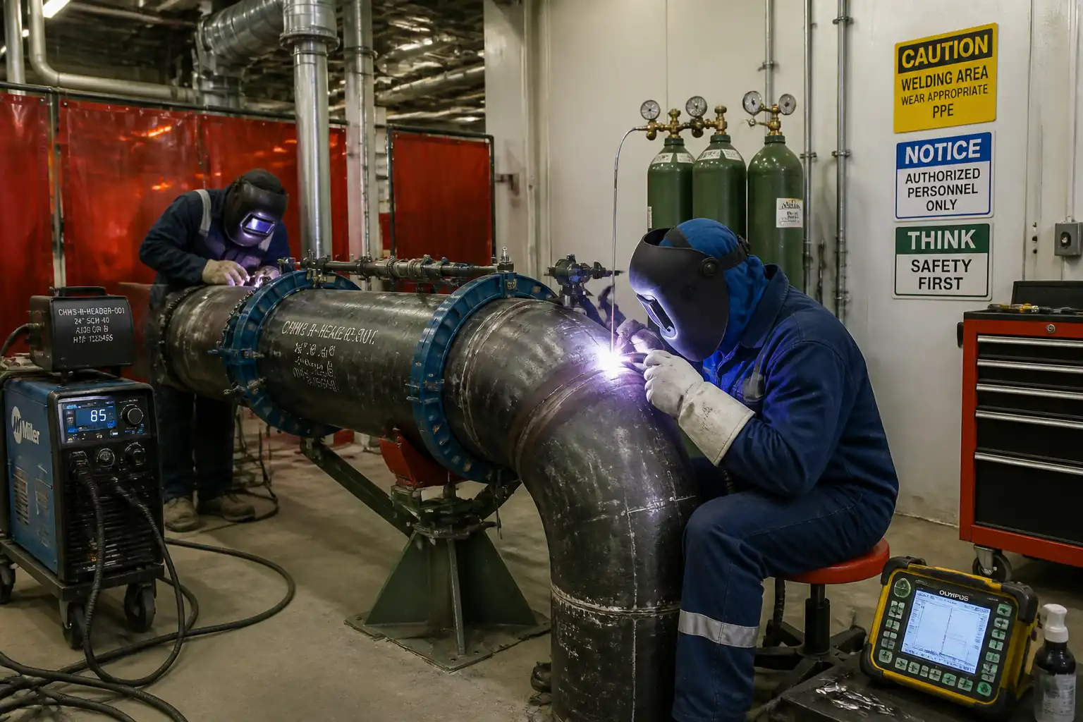
| 4 | Root pass welding | Weld root by approved process (e.g., SMAW E6010 or GTAW) with parameters within WPS ranges. Monitor heat input and travel speed. Ensure internal reinforcement and full penetration. Remove internal clamp after adequate root support. | Welder / Welding Supervisor | In-process surveillance |
| 5 | Hot pass and fill passes | Deposit hot pass to remove internal slag and support subsequent layers; proceed with fill passes in sequence to control distortion. Maintain interpass temp and stagger start/stop positions. | Welder / Welding Supervisor | In-process surveillance |
| 6 | Cap pass and visual inspection (VT) | Complete cap with uniform width and height; grind/feather stop-starts; remove surface spatter and clean. Perform VT after cooling to ambient or as per WPS. | QC Inspector | Visual Testing |
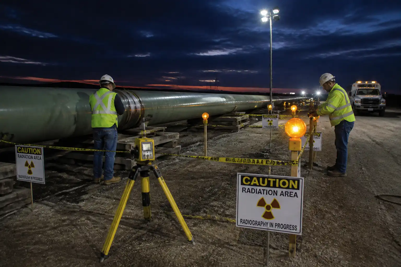
| 7 | NDT (RT/AUT and surface methods) | Perform RT or AUT to specified extent (typically 100% for mainline). Use MT/PT on surface indications or repairs as directed. Control radiography safety zones. | NDT Level II / QC | NDT execution |
| 8 | Repair welding (if required) | Mark defect extents; remove by grinding/gouging at a 3:1 taper; MT/PT to confirm removal. Apply preheat (often +25°C above original WPS [Verify]). Reweld to approved repair WPS. Limit number of repairs (e.g., max 2) before NCR/engineering disposition. | Welding Supervisor / QC / NDT | Defect removal verification |
| 9 | Weld numbering and mapping | Stamp/paint unique weld ID; update weld map showing chainage, heat numbers, WPS, welder IDs, date, NDT status, and repair history. | QC Inspector | Document review |
| 10 | Release to coating | Confirm weld accepted by VT and required NDT; verify bevel clean and dry for coating; ensure required dwell time (if PWHT or hydrogen hold, when applicable) [Verify]. | QC Inspector / Client Rep | Release check |
Health, Safety, and Environment – Safety Controls
Key task-specific hazards and controls
1) Hazard: Hot work (burns, fire, explosion)
- Likely consequence: Severe burns, ignition of ROW vegetation or nearby hydrocarbons
- Engineering/procedural control: Hot Work Permit; segregate flammables; maintain 2 x 9 kg ABC extinguishers per station; fire watch during and 30 min after welding; combustible clearance ≥10 m or fire blankets
- PPE: Flame-resistant clothing (EN ISO 11612), welding helmet with appropriate shade, leather gloves, spats, eye protection, hearing protection
- Collective measure: Designated hot work zones with barriers and signage; wind shields to contain sparks
- Inspection/permit/supervision: Hot Work PTW approval each shift; HSE inspections; supervisor sign-off [Verify per project HSE plan and local regulations]
2) Hazard: Radiography exposure (ionizing radiation, if RT used)
- Likely consequence: Radiation overexposure
- Engineering/procedural control: Licensed RT contractor; controlled exclusion zone with barricades and dosimetry; use of area monitors and time–distance–shielding principles
- PPE: As required by RT procedure; personal dosimeters for RT crew
- Collective measure: Night RT or isolated timing to minimize personnel; radio communication and spotters
- Inspection/permit/supervision: Radiation work permit; RSO oversight; signage and logbooks [Verify regulatory requirements]
3) Hazard: Fumes and shielding gases (oxy-fuel, CO2/Argon) and inadequate ventilation
- Likely consequence: Respiratory irritation, asphyxiation
- Engineering/procedural control: Use local ventilation in shelters; avoid gas accumulation in low spots; monitor oxygen if in partially enclosed areas
- PPE: Respiratory protection if ventilation inadequate (as per monitoring), FR clothing
- Collective measure: Open-side shelters; gas cylinder restraint and leak checks
- Inspection/permit/supervision: Gas storage per code; periodic air quality checks
4) Hazard: Preheat/induction equipment and open flames
- Likely consequence: Burns, fire, hose flashback
- Engineering/procedural control: Flashback arrestors; leak test; secure hoses; maintain clear area around burners; thermal blankets to protect ground
- PPE: Heat-resistant gloves, FR sleeves, face shield for burner operators
- Collective measure: Fire-resistant mats; drip trays for fuel
- Inspection/permit/supervision: Daily equipment checks; PTW validation
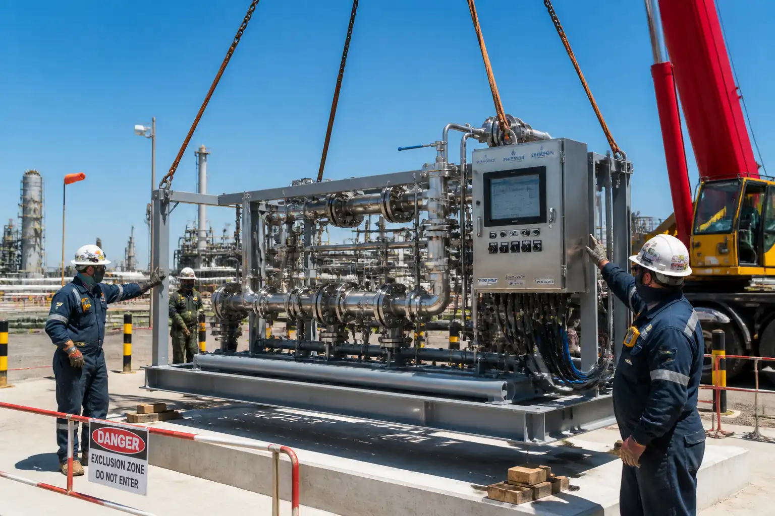
5) Hazard: Line-up clamp and moving pipe/plant
- Likely consequence: Crush injuries, pinch points
- Engineering/procedural control: Exclusion zone around clamp operations; tag-out before clamp removal; certified lifting appliances and slings; signalers
- PPE: Hard hat, safety boots with metatarsal protection, gloves, high-visibility vest
- Collective measure: Banksman control; radio comms; spotters at each end
- Inspection/permit/supervision: Lifting plans; operator certification; pre-use inspection
6) Hazard: Grinding and arc strikes
- Likely consequence: Eye injury, lacerations, fires
- Engineering/procedural control: Guards in place; spark containment; correct discs; no unauthorized arc strikes
- PPE: Face shield + safety glasses, cut-resistant gloves, hearing protection
- Collective measure: Spark curtains; fire watch
- Inspection/permit/supervision: Tools PAT/inspection; permits as required
7) Hazard: Weather (wind, rain, lightning, extreme heat/cold)
- Likely consequence: Poor weld quality, slips, heat stress
- Engineering/procedural control: Stop welding during rain/lightning; wind shields when wind affects gas coverage; hydration program and shaded rest
- PPE: Weather-appropriate FR layers; insulated gloves in cold
- Collective measure: Shelters; non-slip mats
- Inspection/permit/supervision: Supervisor weather checks; work suspension criteria posted
8) Hazard: Noise and vibration
- Likely consequence: Hearing damage
- Engineering/procedural control: Maintain equipment; schedule noisy tasks; use dampening mats
- PPE: Ear plugs/muffs (SNR/NPR per risk)
- Collective measure: Noise signage; rotate crews
- Inspection/permit/supervision: Periodic noise surveys
9) Hazard: Confined or partially enclosed spaces (tie-ins at trenches)
- Likely consequence: Asphyxiation, limited egress
- Engineering/procedural control: Confined space assessment; continuous gas monitoring; rescue plan
- PPE: Harness if required, respirators if specified
- Collective measure: Attendant and entry permits; retrieval system
- Inspection/permit/supervision: Confined Space Entry Permit; supervisor authorization [Verify per local regulations]
Environmental Controls
- Welding shelters/wind screens positioned to minimize spark travel and dust spread.
- Fuel/oxy-fuel cylinders stored on drip trays with spill protection; maintain minimum separation distances; no storage in watercourses or drainage paths.
- Prevent soil contamination: use fire-resistant mats and trays under preheat stations; collect slag/grinding debris for proper disposal.
- Manage noise by scheduling RT generators and welding plants away from sensitive receptors; maintain equipment to reduce noise.
- Air quality: avoid open burning; ensure solvents are low-VOC and used sparingly; lids closed when not in use.
- Waste management: segregate waste (metal offcuts, spent electrodes, used wipes) into labeled containers; dispose per approved waste plan.
- Water protection: prohibit washing solvents into ground; contain water used for cleaning; protect nearby watercourses with silt barriers if trench work nearby.
- Wildlife/vegetation: maintain fire breaks; have extinguishers and water sprayers ready during dry seasons.
- Emergency spill response: spill kits at each welding station; trained personnel; report and document any spills immediately.
- Compliance: adhere to project CEMP and local environmental regulations [Verify per project HSE plan and local regulations].
Quality Assurance and Quality Control
QA/QC Controls
- WPS/PQR: Use only Client-approved WPS with supporting PQRs qualified to API 1104 (or ASME IX/ISO as specified). WPS must list essential variables, heat input limits, preheat/interpass, and acceptance references.
- Welder qualifications: Verify current qualifications for process/position and maintain continuity records with no lapse beyond project limit [Verify per project specifications].
- Consumables: Low-hydrogen electrodes stored in holding ovens 100–150°C; exposure time at ambient not exceeding 4 hours (typical) before re-bake at 300–350°C for 1–2 h [Verify per manufacturer/WPS]. Issue by batch number; log returns.
- Equipment calibration: Welding machines, ammeters/voltmeters, IR thermometers, dew point meters—valid calibration (typically ≤12 months) with daily function checks recorded.
- Environmental criteria: Do not weld if surfaces are wet or temperature is within 3°C of dew point. Wind speed limits for GMAW/GTAW as per WPS; provide wind breaks as required.
- Fit-up tolerances: Root gap 2.0–3.0 mm; hi-lo ≤1.6 mm unless otherwise qualified; bevel angle 30°±5°; land 1.6±0.8 mm [Verify per WPS].
- Interpass cleaning: Remove slag/oxides between passes; grind starts/stops; no peening unless WPS qualified.
- Visual inspection: 100% VT with acceptance per API 1104. Record reinforcement, undercut, surface discontinuities.
- NDT: Extent per project (typ. 100% RT/AUT mainline). MT/PT for suspect indications and after defect removal.
- Repairs: Execute to approved repair WPS, with enhanced preheat if specified; limit repair cycles (typ. ≤2) before NCR/concession.
- Records & traceability: Weld map linking joint ID to pipe heat numbers, WPS, welders, parameters, NDT outcome, and repairs. Retain records for turnover.
- Hold/Witness points: Key holds at fit-up, post-VT pre-NDT, and final acceptance/release to coating; witness at preheat checks and mapping.
Document Control
- All forms to carry project, line, chainage, weld ID, date/time, and signatures.
- Retain original NDT films/data and calibration certificates in turnover dossier.
- NCR and concession procedures per project QMS; corrective actions tracked to closure.
Attachments
- Sample WPS summary sheet and supporting PQR abstracts
- Welder Qualification Test Records (WQTR) and continuity log template
- Fit-up inspection checklist and weld parameter log sheet
- Preheat/interpass temperature log sheet
- Weld mapping template and traceability matrix
- NDT request form and reporting templates (RT/AUT/MT/PT)
- Repair welding procedure template and repair log
- Equipment calibration register (weld machines, meters, thermometers)
- Oven temperature log and consumable issue/return log
- Hot Work Permit, JSA template, and RT radiation safety plan outline
This content is a read-only public reference. Download or customize to get an editable version.
ITP preview
The first inspection activities from the linked ITP for Method Statement – Oil & Gas Pipeline Welding Works (WPS, Welder Qualification, Fit-Up, Preheat, Welding, NDT, Repairs, Traceability):
| Activity | Inspection / Test | Acceptance Criteria | Responsibility | Record |
|---|---|---|---|---|
| Material verification and joint prep | Visual/dimensional check of pipe grade, bevel, heat marks | Matches IFC; bevel geometry per WPS; cleanliness SSPC-SP1 | QC Inspector | Material/JPC checklist and photos |
| Fit-up inspection (Hold) | Gap/hi-lo using gauges; alignment at 4 quadrants | Root gap 2–3 mm; hi-lo ≤1.6 mm or per WPS; joint ID marked | QC Inspector; Witness: Client Rep | Fit-up report (H) |
| Preheat/interpass verification | IR thermometer/temp crayons; dew point measurement | Preheat ≥ WPS; interpass ≤ WPS; surface ≥3°C above dew point | Welder / QC Inspector | Preheat log; environmental checklist |
Showing 3 of 10 inspection activities. View full ITP →
Related Inspection and Test Plan
An Inspection and Test Plan (ITP) is available for Method Statement – Oil & Gas Pipeline Welding Works (WPS, Welder Qualification, Fit-Up, Preheat, Welding, NDT, Repairs, Traceability). The ITP defines the inspection activities, acceptance criteria, hold and witness points, responsible parties, and records required to verify the work described in this method statement.
View the Method Statement – Oil & Gas Pipeline Welding Works (WPS, Welder Qualification, Fit-Up, Preheat, Welding, NDT, Repairs, Traceability) ITP →Frequently asked questions
Continue with related Quollnet resources connected to this method statement.