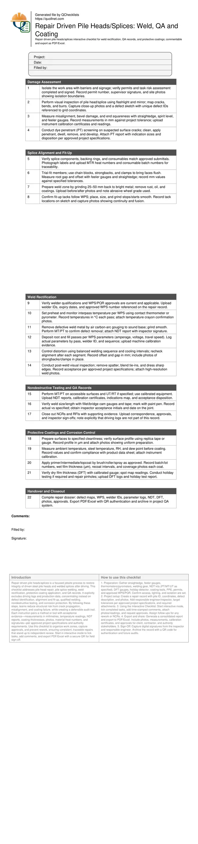
Repair Driven Pile Heads/Splices: Weld, QA and Coating
Definition: Repair driven pile heads/splices checklist for site engineers and inspectors, covering damage assessment, weld rectification, QA documentation, and protective coatings, while excluding production pile driving logs.
- Identify and record damage with measurable evidence and photos.
- Align and rectify splices using WPS-driven methods and NDT acceptance.
- Seal repairs with compliant protective coatings and traceable batch records.
- Interactive, commentable, export options with QR code verification.
Repair driven pile heads/splices is a focused jobsite process to restore integrity of driven steel pile heads and welded splices after driving. This checklist addresses pile head repair, pile splice welding, weld rectification, protective coating application, and QA records. It explicitly excludes driving logs and production data, concentrating instead on defect identification, alignment and fit-up, qualified welding, nondestructive testing, and corrosion protection. By following these steps, teams reduce structural risk from crack propagation, misalignment, and coating failure, while creating a defensible audit trail. Each instruction pairs a method or tool with acceptance evidence—measurements in millimetres, temperature readings, NDT reports, coating thicknesses, photos, material heat numbers, and signatures—per approved project specifications and authority requirements. Use this checklist to organize work zones, capture approvals, and prevent rework, ensuring consistent, traceable repairs that stand up to independent review. Start in interactive mode to tick tasks, add comments, and export PDF/Excel with a secure QR for field sign-off.
- Ensure damaged pile heads and splices are restored with controlled alignment, qualified weld rectification, and validated protective coatings. Each action captures measurable evidence and traceable approvals, reducing rework and strengthening compliance without mixing in pile driving logs or production metrics.
- Document welds with WPS/PQR references, welder IDs, preheat and interpass temperatures, and calibrated NDT. Visual, MT/PT, and UT where specified provide objective acceptance, while NCR closures and RFIs are consolidated into a single QA record ready for client review.
- Seal repaired zones with correctly prepared surfaces, verified profile, and coating systems applied to data sheet requirements. Environmental conditions, wet and dry film thicknesses, holiday testing, and batch numbers produce a corrosion-control record that supports long-term durability in aggressive environments.
- Interactive online checklist with tick, comment, and export features secured by QR code.
Damage Assessment
Splice Alignment and Fit-Up
Weld Rectification
Nondestructive Testing and QA Records
Protective Coatings and Corrosion Control
Handover and Closeout
Assess Damage and Prepare Pile Heads/Splices
Start by safely isolating the work area and confirming permits are in place. Thoroughly inspect the pile head and splice using visual methods, mirrors, and lighting to identify cracks, lamination, and deformation from driving. Quantify misalignment, root gaps, and end squareness with a straightedge, feeler gauges, and level; log measurements in millimetres against project tolerances. Where surface cracking is suspected, apply dye penetrant to reveal indications before any grinding. Remove contamination—rust, mill scale, oil, and old coatings—within 25–50 mm of the intended weld area by controlled grinding. Clearly tag the repair with a unique ID and sketch its location relative to survey grid lines so teams can coordinate access and materials. This disciplined front-end assessment prevents chasing hidden defects or welding over contamination, both of which cause rework. Evidence is essential: take clear photos, note instrument serial numbers, and collect signatures to build a defensible QA record per approved project specifications and authority requirements.
- Isolate, permit, and document the work zone.
- Map defects with photos and unique IDs.
- Measure misalignment and gaps in millimetres.
- Use PT to reveal surface cracking early.
- Grind 25–50 mm to bright metal.
Rectify Welds and Control Alignment
Execute weld rectification under an approved WPS using qualified welders. Verify preheat and interpass temperatures with calibrated devices and document readings for each pass. Remove unsound metal by air carbon-arc gouging, then grind smooth and confirm soundness with MT/PT before rewelding. For fit-up, hold alignment with strongbacks and clamps; use a balanced weld sequence to limit distortion and remeasure offsets throughout. Log actual parameters—amperage, voltage, travel speed—and the welder ID on every pass. After welding, perform thorough visual inspection, blending starts and stops and removing spatter. Apply NDT as specified: MT/PT on surfaces and UT or RT where required. Acceptance is based on the project specification; record pass/fail decisions with signatures. This methodical approach safeguards load transfer through the splice and prevents long-term fatigue issues caused by misalignment or residual defects.
- Follow WPS with qualified welders.
- Record preheat and interpass temperatures.
- Gouge, grind, and verify defect removal.
- Balance welding to reduce distortion.
- Document NDT results and acceptances.
Protective Coatings and Quality Records
After acceptance, protect repaired areas against corrosion. Prepare surfaces to the specified cleanliness and verify surface profile using replica tape or a profile gauge; record the profile in micrometres. Check environmental conditions—steel temperature, ambient temperature, relative humidity, and dew point—ensuring they meet coating data sheet limits. Apply the specified system by brush, roller, or spray, documenting batch numbers, wet film thickness, and recoat intervals. Measure dry film thickness at multiple points, mapping results and repairing any low readings. Perform holiday testing where required and retest after touch-ups. Finally, consolidate the QA package: WPS/PQR references, welder and inspector credentials, parameter logs, NDT reports, coating logs, photos, NCR closures, and approvals. Export the verified dossier to PDF/Excel and secure with a QR code to authenticate the record trail.
- Verify surface profile in micrometres.
- Record environmental conditions before coating.
- Log batch numbers and film thicknesses.
- Map DFT readings and repair lows.
- Export a QR-secured QA dossier.
How to Use This Interactive Repair Checklist
- Preparation: Gather straightedge, feeler gauges, thermometers/pyrometers, welding gear, NDT kits (PT/MT/UT as specified), DFT gauges, holiday detector, coating tools, PPE, permits, and approved WPS/PQR. Confirm access, lighting, and isolation are set.
- Project setup: Create a repair record with pile ID, coordinates, defect description, and photos. Add responsible engineer/inspector, target tolerances per approved project specifications, and required attachments.
- Using the Interactive Checklist: Start interactive mode, tick completed tasks, add time-stamped comments, attach photos/readings, and request approvals. Assign follow-ups for any rework or NCRs.
- Export and share: Generate a consolidated report and export to PDF/Excel. Include photos, measurements, calibration certificates, and approvals for client, contractor, and authority stakeholders.
- Sign-Off: Capture digital signatures from the inspector and responsible engineer. Archive the record with a QR code for authentication and future audits.
Call to Action
- Start Checklist Tick off tasks, leave comments on items or the whole form, and export your completed report to PDF or Excel—with a built-in QR code for authenticity.
- Download Excel - Driven Pile Head/Splice Repair Checklist
- Download PDF - Driven Pile Head/Splice Repair Checklist
- View Image - Driven Pile Head/Splice Repair Checklist
Cite & Embed
“Driven Pile Head/Splice Repair Checklist by Quollnet”
with a link to
this source page.
FAQ
Question: What defects typically require weld rectification at driven pile heads or splices?
Question: How do I choose between grinding out a small defect and removing the entire weld segment?
Question: What environmental limits should I observe before applying protective coatings?
Question: Which QA records are essential to close a pile head/splice repair?
Related Articles
Broader reading and guidance connected to this checklist topic.


Improve Your Project Handover Process With Snag List Tracking App

Related Checklists
Keep the workflow moving with nearby templates chosen from similar checklist content.