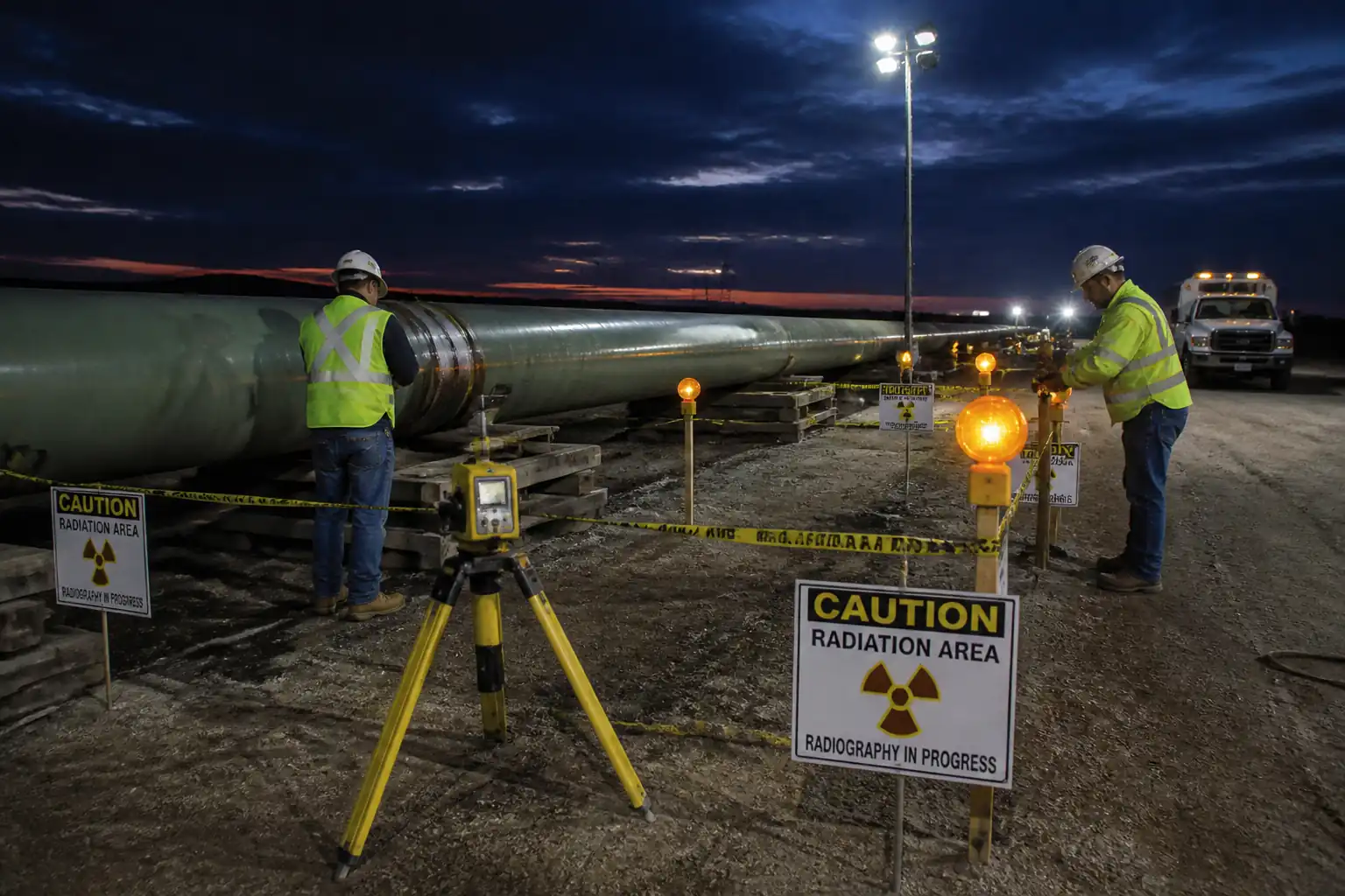

Inspection and Test Plan for Method Statement: Coordination and Execution of NDT for Oil & Gas Pipeline Welds (RT/UT)
AI-assisted inspection and test plan connected to a method statement, with PDF and Excel export.
More than a static template
Unlike a downloadable Word or PDF template, this ITP is an AI-assisted editable starting point directly connected to its method statement. Every inspection activity, hold point, and acceptance criterion is structured and ready to adapt to your project.
- AI-assisted customization — Tailor inspection activities and acceptance criteria to your specific project scope.
- Linked method statement — This ITP is connected to the corresponding method statement describing the work sequence.
- Multiple export formats — Download as a formatted PDF or editable Excel spreadsheet.
- Editable starting point, not a final document — Review and verify all content against your project specifications and standards before use.
What you can customize
When you save this ITP to your account, every inspection row becomes editable. You can add, remove, or modify:
- Inspection activity — Description of what is being inspected.
- Inspection type — Hold point (H), Witness point (W), Review (R), or Monitor (M).
- Responsibility — Contractor, subcontractor, engineer, or client.
- Frequency — How often the inspection occurs.
- Acceptance criteria — Referenced standard or specification requirement.
- Records — Forms, test reports, or checklists required as evidence.
Why this ITP is used
To control and verify NDT activities meet contractual, code, and safety requirements for pipeline weld integrity.
Who uses this inspection and test plan
Contractor QC, NDT subcontractor, Client/Engineer, and HSE teams during construction and pre-commissioning.
When this ITP is prepared and submitted
From pre-mobilization through execution of NDT and until final turnover of the NDT dossier.
Who receives or approves this ITP
Client/Engineer per contract for review/approval.
Inspection scope
Procedure approvals, equipment calibration, weld identification, VT hold point, RT/UT setup and execution, interpretation, repairs, retesting, and dossier review.
Typical hold, witness, and review points
Pre-NDT VT (H), RT setup boundary check (W), UT calibration (W), results disposition (H), final dossier (H).
Typical inspection records
Approved procedures, permits, calibration sheets, VT/NDT reports, images, repair logs, retest reports, survey logs, MDR index.
Important approval note
This ITP is an AI-assisted editable starting point, not a pre-approved document. Before use on any project, all inspection activities, hold points, and acceptance criteria must be reviewed and approved by the relevant parties (superintendent, principal contractor, or client representative) in accordance with your contract and project quality plan.
Always verify acceptance criteria against your applicable drawings, specifications, and regulatory requirements. Hold points must be confirmed with the relevant authority before work proceeds past that point.
Inspection and test plan
| Activity | Inspection / Test | Acceptance Criteria | Responsibility | Record |
|---|---|---|---|---|
| Procedure approvals (RT/UT) and personnel qualifications | Review and approval | Procedures signed by Level III and approved by Client; personnel certifications valid per ISO 9712/SNT-TC-1A. | Contractor QC / NDT Level III / Client Rep | Approved procedures, approval letters, certs |
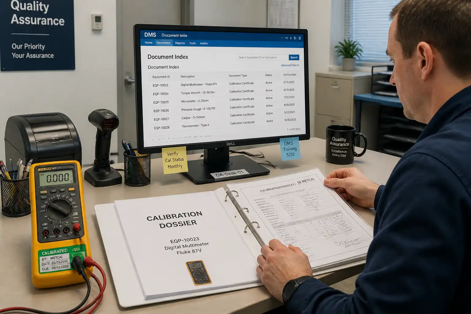
| Equipment calibration and validity | Calibration verification | Calibration in date; daily function checks recorded; survey meters and densitometer verified. | NDT Level II / QC | Cal certs, daily checks |
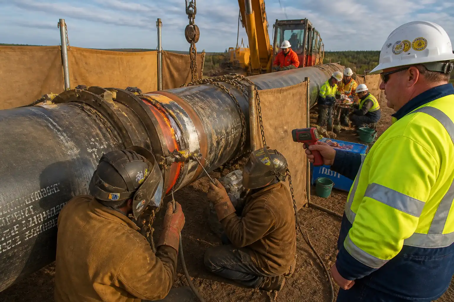
| Weld identification and mapping | Document/field check | Unique weld IDs; mapping accuracy within specified tolerances. | QC / Surveyor | Weld tally, maps |
| Pre-NDT VT hold point | VT | VT acceptable per code; cleanliness and readiness confirmed. | QC Inspector / Client Rep | VT report, release for NDT |
| NDT Request issuance | Document review | Correct method, extent, welder/day randomization traceable. | QC Manager | NDT Request |
| RT technique setup and boundary check | Technique verification and dose survey | Technique as per standard; boundary dose within limits; IQI and markers correct. | Radiographer / RPO / Client Rep | Technique sheet, survey log |
| RT exposure and film/CR processing | Density/IQI check | Density range and IQI sensitivity met; image quality acceptable; IDs visible. | Radiographer Level II | RT images, density log |
| RT interpretation and disposition | Evaluation | Acceptance per API 1104/Project; report completed and signed. | Radiographer Level II / Level III / QC | RT report |
| UT calibration and sensitivity set-up | Calibration check | Valid DAC/TCG; reference reflectors met; coverage plan approved. | UT Level II / Client Rep | UT calibration sheet |
| UT scanning and evaluation | UT examination | 100% coverage of weld volume [Verify]; acceptance per contract code; indications sized and located. | UT Level II / QC | UT report |
| Repair verification (VT) | VT | Repaired area acceptable for retesting; WPS parameters followed. | QC Inspector / Welding Supervisor | VT record, repair log |
| Retesting after repair (RT/UT) | RT/UT | Repaired area plus ≥50 mm each side free of unacceptable indications. | NDT Level II / QC / Client Rep | Retest report/images |
| Final dossier and MDR submission | Document audit | Complete, indexed, signed and approved; traceability confirmed. | QC Manager / Document Controller | NDT dossier, MDR index |
This table is a read-only public reference. Download the PDF or Excel version, or customize this ITP to edit it for your project.
Frequently asked questions
Related method statement
This Inspection and Test Plan is associated with the Method Statement: Coordination and Execution of NDT for Oil & Gas Pipeline Welds (RT/UT) method statement, which describes the step-by-step construction sequence, resources, materials, equipment, safety controls, and environmental controls for this activity.
View the Method Statement: Coordination and Execution of NDT for Oil & Gas Pipeline Welds (RT/UT) method statement →Continue with related inspection, method statement, article, and checklist resources.