Inspection and Test Plan for Method Statement: Metering Skid Installation for Oil & Gas Service
AI-assisted inspection and test plan connected to a method statement, with PDF and Excel export.
More than a static template
Unlike a downloadable Word or PDF template, this ITP is an AI-assisted editable starting point directly connected to its method statement. Every inspection activity, hold point, and acceptance criterion is structured and ready to adapt to your project.
- AI-assisted customization — Tailor inspection activities and acceptance criteria to your specific project scope.
- Linked method statement — This ITP is connected to the corresponding method statement describing the work sequence.
- Multiple export formats — Download as a formatted PDF or editable Excel spreadsheet.
- Editable starting point, not a final document — Review and verify all content against your project specifications and standards before use.
What you can customize
When you save this ITP to your account, every inspection row becomes editable. You can add, remove, or modify:
- Inspection activity — Description of what is being inspected.
- Inspection type — Hold point (H), Witness point (W), Review (R), or Monitor (M).
- Responsibility — Contractor, subcontractor, engineer, or client.
- Frequency — How often the inspection occurs.
- Acceptance criteria — Referenced standard or specification requirement.
- Records — Forms, test reports, or checklists required as evidence.
Why this ITP is used
To control quality and ensure compliance with codes, vendor requirements, and contractual specifications at defined hold and witness stages.
Who uses this inspection and test plan
Contractor QC, Site Engineers, Client/Engineer, and Vendor Representatives use the ITP to verify and witness activities.
When this ITP is prepared and submitted
From material receipt through placement, anchoring, E&I works, testing, proving, and final turnover.
Who receives or approves this ITP
Client/Engineer for approval and witnessing.
Inspection scope
Covers receipt, foundations, lifting readiness, placement, anchoring, grouting, torque, E&I terminations, pneumatic tests, functional checks, proving, and final dossier.
Typical hold, witness, and review points
Holds: Pre-grout, pneumatic pressure test, proving/calibration. Witness: Receipt, foundation survey, lifting, placement, torque, E&I tests, final walkdown.
Typical inspection records
Receiving IRs, survey reports, anchor/grout logs, torque sheets, pressure test certs, ITRs, calibration reports, MDR index.
Important approval note
This ITP is an AI-assisted editable starting point, not a pre-approved document. Before use on any project, all inspection activities, hold points, and acceptance criteria must be reviewed and approved by the relevant parties (superintendent, principal contractor, or client representative) in accordance with your contract and project quality plan.
Always verify acceptance criteria against your applicable drawings, specifications, and regulatory requirements. Hold points must be confirmed with the relevant authority before work proceeds past that point.
Inspection and test plan
| Activity | Inspection / Test | Acceptance Criteria | Responsibility | Record |
|---|---|---|---|---|
| [H] Review of IFC, vendor manuals, lift plan, and ITP | Documents verified current and approved | All documents approved for construction/use; revisions match site issue | Contractor QC / Client | Document review checklist, approvals |
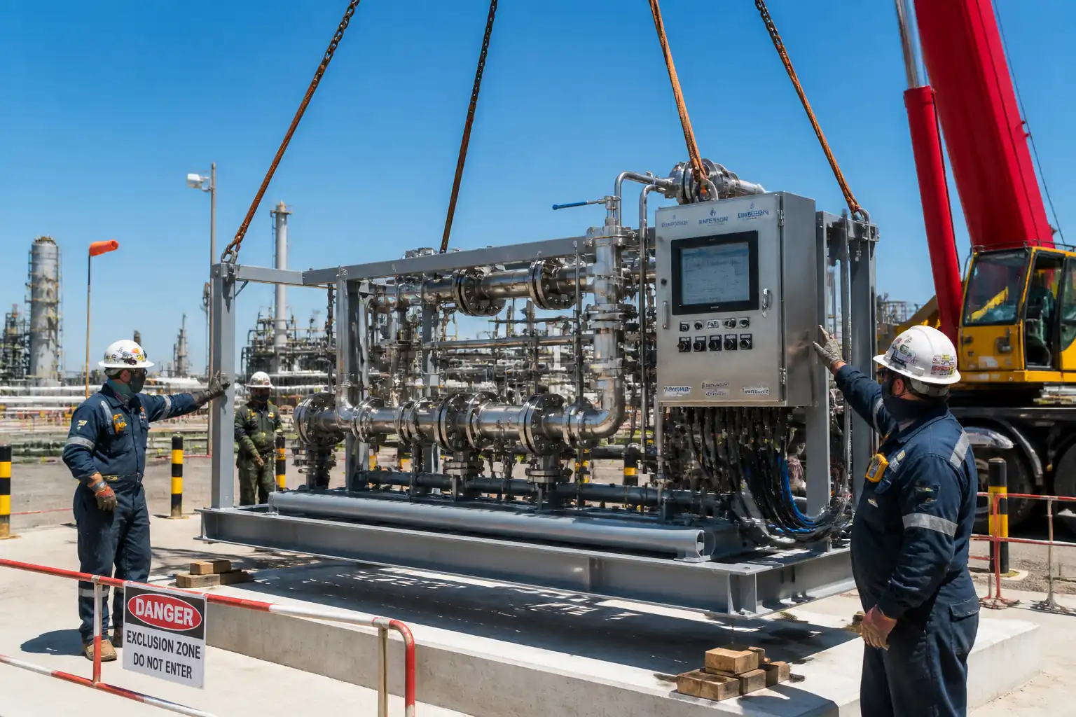
| [W] Receipt inspection & preservation status | Visual inspection, preservation seal check | No damage/corrosion; all ports capped; items match packing list | QC Inspector / Client | Receiving IR, photos |
| [W] Foundation level/position survey | Instrument survey readings | Elevation and plan within tolerances; concrete strength verified | Surveyor / QC / Client | Survey report, concrete test reports |
| [W] Pre-lift inspection | Rigging certificates, pre-use inspection | Rigging WLL adequate; lift plan signed; exclusion zone established | Lifting Supervisor / QC / Client | Pre-lift checklist |
| [W] Placement and orientation check | Level/orientation reading | Temporary level ≤ 2 mm/m; flow direction correct | Site Engineer / QC / Client | Placement IR |
| [W] Anchor hole inspection (post-installed) | Hole dia/depth, cleanliness | Per adhesive TDS and design; no rebar damage | QC / Client | Anchor inspection sheet |
| [H] Pre-grout hold | Level, shim/sole plates, formwork | Level ≤ 1 mm/m; grout access/vents provided; clearances confirmed | QC / Client | Pre-grout IR |
| [W] Grouting operations | Placement monitoring; samples taken | Continuous flow; no voids; samples labelled | QC / Client | Grout log; test results |
| [W] Final torque and level verification | Torque readings, level survey | Torque per spec; level maintained | QC / Client | Torque sheet, level report |
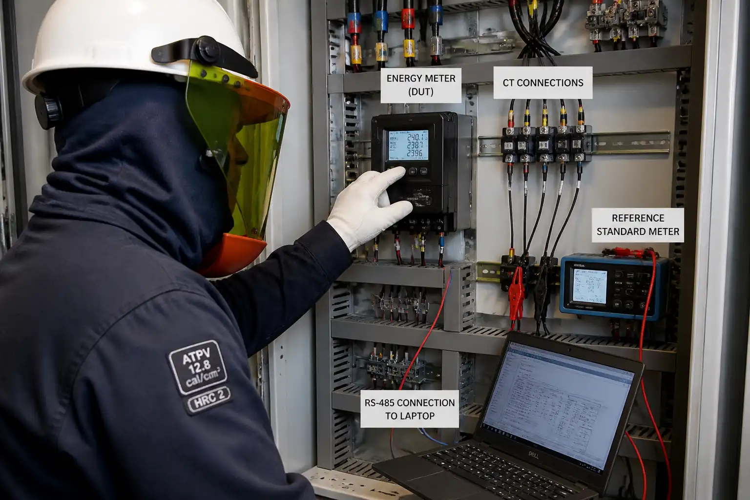
| [W] E&I terminations and IR/continuity | IR at 500 VDC; continuity; gland inspection | IR ≥ project min; correct cores; Ex/IP maintained | QC (E&I) / Client | ITR-E&I test sheets |
| [H] Pneumatic leak/pressure test (tubing/connections) | Pressurization and hold; soap/helium check | No bubbles; pressure drop ≤ 1% over agreed hold [Verify] | QC / Client | Pressure test certificate |
| [W] Functional and loop checks | Signal simulation and verification | Function per cause/effect; scaling correct; accuracy within limits | Commissioning / QC / Client | Loop ITRs |
| [H] Meter proving/calibration | Prover runs; K-factor calculations | Repeatability/linearity within vendor/API limits [Verify] | Vendor / Client | Calibration report, data files |
| [W] Final walkdown and turnover | Punchlist close-out; MDR review | All ITRs complete; punches closed/accepted; MDR per index | QC / Client | Final IR; MDR acceptance |
This table is a read-only public reference. Download the PDF or Excel version, or customize this ITP to edit it for your project.
Frequently asked questions
Related method statement
This Inspection and Test Plan is associated with the Method Statement: Metering Skid Installation for Oil & Gas Service method statement, which describes the step-by-step construction sequence, resources, materials, equipment, safety controls, and environmental controls for this activity.
View the Method Statement: Metering Skid Installation for Oil & Gas Service method statement →Continue with related inspection, method statement, article, and checklist resources.