Method Statement: Installation of Air-Cooled Chillers on Rooftop Structural Steel Frames – Method Statement
AI-assisted method statement with matching ITP, PDF download, and Excel export.
More than a static template
Unlike a downloadable Word or PDF template, this method statement is an AI-assisted editable starting point connected directly to a matching Inspection and Test Plan. Every section is structured, project-adaptable, and ready to export.
- AI-assisted drafting — Customize every section with AI for your specific project scope.
- Linked ITP — A matching inspection and test plan is generated alongside the method statement.
- Multiple export formats — Download as a formatted PDF or editable Excel spreadsheet.
- Editable starting point, not a final document — Review, verify, and adjust all content against your project requirements before use.
Static template vs. Quollnet workflow
| Feature | Static template | Quollnet |
|---|---|---|
| Project-specific content | Manual fill-in required | AI-assisted customization |
| Linked ITP | Separate document, no link | Matching ITP included |
| Export formats | Usually PDF only | PDF and Excel |
| Structured sections | Free-form layout | 13 standardized sections |
| Saved to your account | Local file only | Cloud-saved, reusable |
| Content accuracy | You verify everything | AI-assisted, you still verify |
| Cost | Often free but time-intensive | Free to customize and download |
What you can customize
When you save this method statement to your account, every section becomes editable. The following 13 sections are included:
- Scope — Defines the activity and its boundaries.
- References — Standards, specifications, and drawings.
- Responsibilities — Roles and accountabilities.
- Resources — Labour, plant, and equipment summary.
- Materials — Materials and compliance requirements.
- Equipment — Tools and equipment details.
- Prerequisites — Hold points and pre-conditions.
- Method sequence — Step-by-step construction sequence.
- Safety controls — HSE risk controls and PPE.
- Environmental controls — Environmental mitigation measures.
- QA/QC — Quality inspection and test requirements.
- ITP — Inspection and Test Plan table (has its own page).
- Attachments — Referenced drawings and documentation.
Why this method statement is used
This method statement is used to define and communicate the approved procedure for carrying out method statement: installation of air-cooled chillers on rooftop structural steel frames on site. It ensures the work is planned in advance, the correct resources and controls are in place, and all personnel understand responsibilities, sequence, quality requirements, and safety controls before work begins. It aligns site execution with the documented scope and acceptance expectations.
Who uses this method statement
This method statement is used by contractors, site supervisors, project engineers, QA/QC engineers, HSE officers, consultants, and client representatives. It serves as a shared reference for planning, execution, supervision, inspection, and approval of the activity on site.
When it is prepared and submitted
The method statement is prepared before the work activity starts and submitted as part of the pre-construction documentation package for review and approval.
Who reviews or approves it
The method statement is usually submitted to the client representative, consultant, resident engineer, or project management consultant for review and approval before the work commences.
Important approval note
This method statement is an AI-assisted editable starting point, not a pre-approved document. Before use on any project, all content must be reviewed and approved by the relevant parties (superintendent, principal contractor, or client representative) in accordance with your contract and project quality plan.
For example: if your specification requires a departure from a referenced standard, that departure must be documented and approved separately — this method statement will not capture that automatically. Always verify against your applicable drawings, specifications, and regulatory requirements.
Method statement content
Scope
Work Included
- Engineering verification of rooftop steel frame capacity and load path for air-cooled chillers and temporary lift loads.
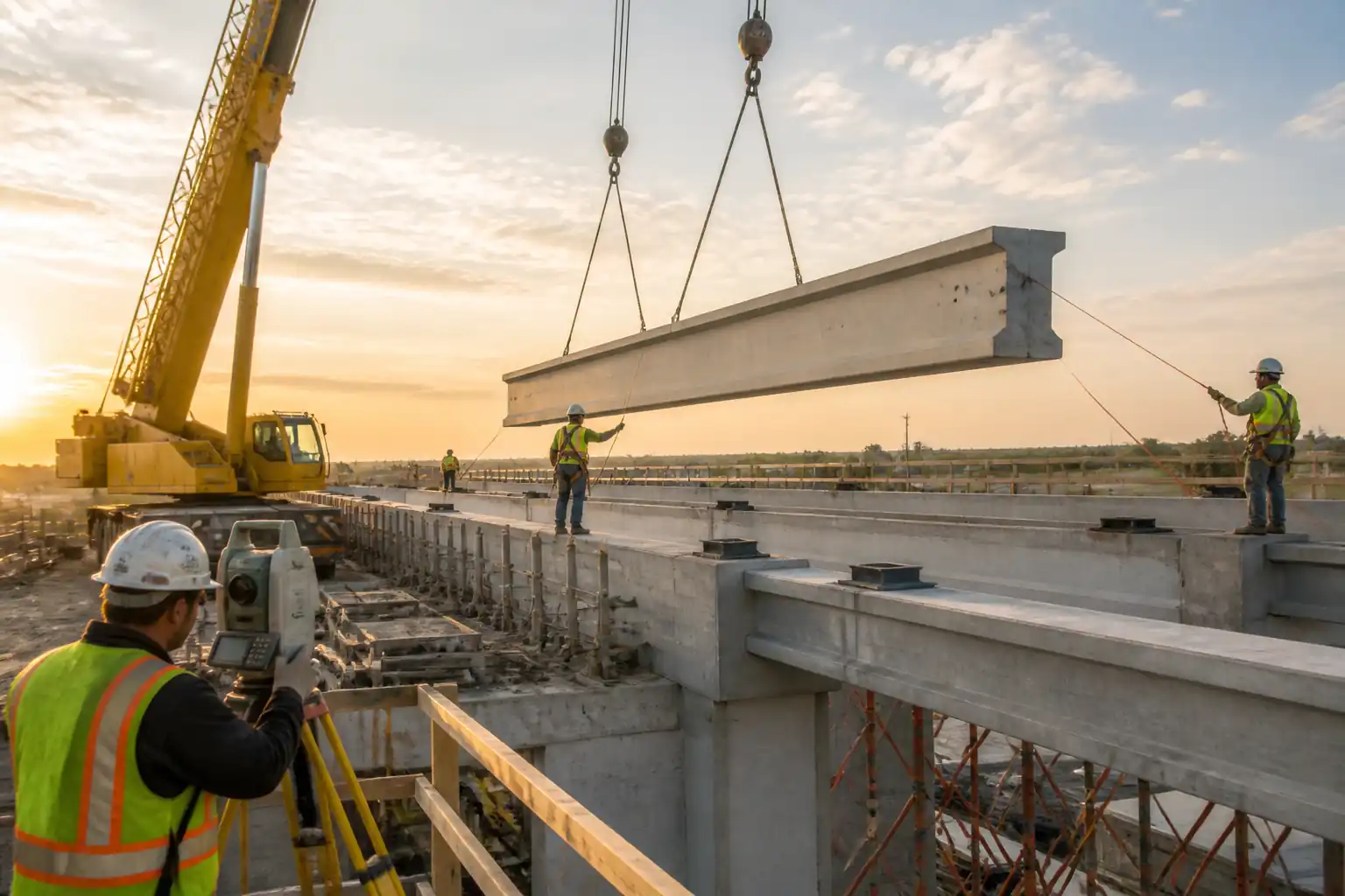
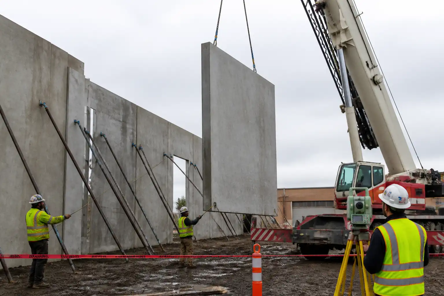
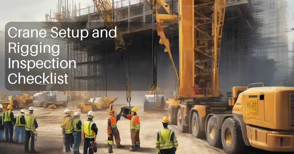
- High-capacity mobile crane setup, rigging, controlled lift, and placement of air-cooled chiller units on rooftop structural steel frames.
- Installation, leveling, and alignment of anti-vibration spring mounts and snubbers as per design.
- Installation of wind restraint/seismic restraint anchors to frames/roof structure.
- Connection of chilled water (CHW) supply/return pipework at chiller headers, including flexible connectors, strainers, valves, and expansion compensation as indicated.
- Pressure testing, flushing (initial) of immediate chiller connection spools where within scope, and pre-commissioning checks pending full system commissioning by others.
- Outdoor/weather protection safety measures during lifting, roof access, and works at height.
Exclusions
- Electrical power/control cabling beyond chiller integral controls unless explicitly instructed.
- Refrigerant piping works (factory-charged packaged chillers assumed).
- Full hydronic system flushing/chemical cleaning and final commissioning (by specialist/others unless stated).
- Permanent architectural/weatherproofing or insulation beyond immediate penetrations unless shown on drawings.
Key Performance Requirements
- Chiller base level: within ±2 mm per meter and ±4 mm overall across footprint [Verify per manufacturer].
- Spring isolator deflection: within ±10% of calculated static deflection; minimum design deflection per drawings (typically 25–50 mm) [Verify per design].
- Wind restraint installation: anchors installed per approved data (ETA/ICC-ES), torque per manufacturer, edge distances and embedment per design; proof testing where specified.
- Pipework connections: aligned without imposed strain; hydrostatic/pressure tests to 1.3–1.5 × design pressure; zero visible leaks [Verify per project specs].
- Lift operations: within crane load chart limits; wind limits per crane OEM; no personnel under suspended loads; exclusion zone enforced.
References
| Document Type | Reference / Number | Revision | Notes |
|---|---|---|---|
| ASME B30.5; ISO 12480-1; BS 7121 [Verify jurisdiction] | |||
| ASME B30.9; ASME B30.26 [Verify jurisdiction] | |||
| AISC 360/ASD/LRFD or EN 1993 (Eurocode 3); ASTM F3125 (A325/A490) bolt grades | Bolt tension per manufacturer/approved torque table [Verify]. | ||
| ACI 318 (Anchoring to Concrete); ICC-ES AC193/AC01; EAD 330232 (ETA) | Follow anchor ETA/ICC-ESR for installation and proof loads [Verify]. | ||
| ASHRAE Guidelines; ISO 10846 (vibration isolation—measurement) | Use manufacturer data for static deflection and snubber clearances. | ||
| ASME B31.9 or BS EN 14336; BSRIA BG 29 for pre-commission cleaning [Verify] | |||
| ASTM A193/A194 (as applicable), Manufacturer standards (e.g., Victaulic) | |||
| IEC 60364 or NFPA 70 (NEC) [Verify jurisdiction] | For any electrical isolation or checks related to chiller energization. | ||
| ISO 12944 (corrosion protection of steel) | Touch-up of damaged coatings on frames/fasteners as needed. |
Responsibilities
| Role | Responsibility | Name / Party |
|---|---|---|
| Project Manager | Project Manager | Contractor |
| Site Manager | Construction/Site Manager | Contractor |
| Lifting Supervisor | Appointed Person / Lifting Supervisor | Contractor |
| Crane Operator | Certified Crane Operator | Subcontractor |
| Rigger/Banksman | Riggers / Banksman | Contractor |
| Structural Engineer | Structural Engineer | Contractor/Designer |
| MEP Supervisor | MEP Supervisor / Pipefitters | Contractor |
| QA/QC Engineer | QA/QC Engineer | Contractor |
| HSE Officer | HSE Manager / Officer | Contractor |
| Vendor Rep | Chiller Vendor Representative | Supplier |
Resources
| Resource Type | Description | Quantity | Remarks |
|---|---|---|---|
| Manpower | 1 | ||
| Manpower | 3–6 [Verify] | ||
| Manpower | 4–8 [Verify] | ||
| Manpower | 1 | ||
| Manpower | 1 | ||
| Manpower | 1 |
Materials
| Material | Specification / Grade | Quantity | Remarks |
|---|---|---|---|
| Air-cooled chiller unit | Per vendor datasheet; ASHRAE compliant | As per BOQ | |
| Spring isolators | Per acoustic/vibration design; ISO 10846 ref | Per unit supports | |
| Anchors, rods, plates | ACI 318/ETA compliant; ISO 12944 coating class [Verify] | As per design | |
| Flexible connectors | Pressure rating ≥ system design + margin [Verify] | 2 per chiller (typical) | |
| CHW fittings and valves | ASME B31.9; manufacturer requirements | As per drawings | |
| Grout/Shims | ASTM C1107 (grout) [Verify] | As required | |
| Sealant/boots | Per roofing system approval [Verify] | As required |
Equipment
| Equipment | Capacity / Type | Quantity | Inspection Required |
|---|---|---|---|
| Mobile crane | [Verify: e.g., 250–500 t] | 1 | Pre-use + third-party cert |
| Rigging gear | Per calc | Set | Pre-use |
| MEWP | Working height per roof | As required | Pre-use |
| Torque wrench | Up to required bolt sizes | 2 | Yes |
| Survey equipment | 1 | Calibration cert | |
| Drilling equipment | 1–2 | Pre-use | |
| Pressure test kit | Up to test pressure | 1 set | Calibration cert |
Prerequisites
- Approved shop drawings, structural calculations for rooftop frames, and anchor details. Confirm allowable roof reactions, deflection limits, and dynamic loads from chillers and wind/seismic.
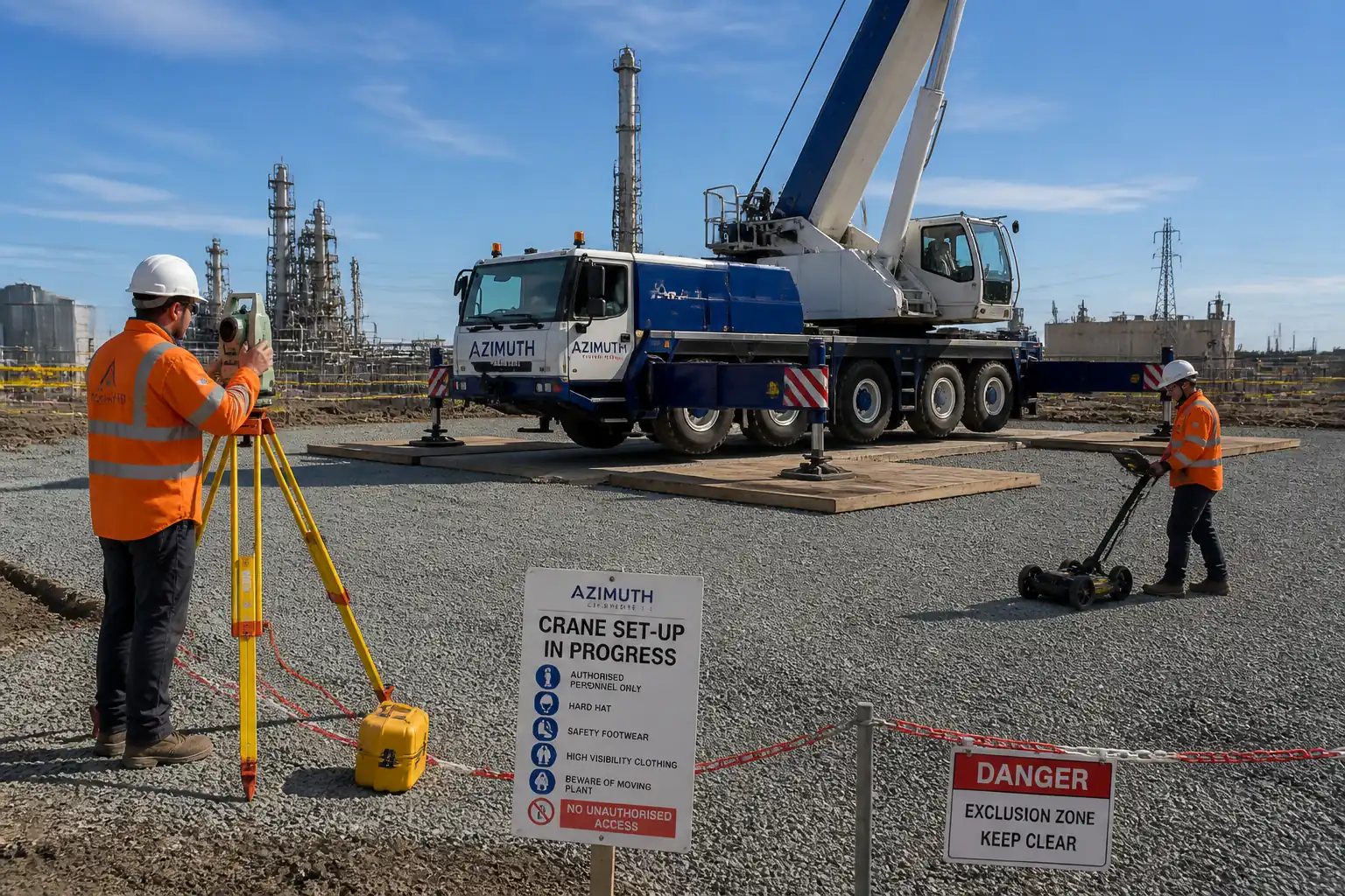
- Approved Lift Plan with rigging calculations, crane load chart checks, ground bearing pressure assessment, outrigger mat design, and route/laydown logistics.
- Permits: Lifting Permit, Work at Height Permit, Hot Works (if any), Roof Access Permit, Electrical Isolation (if any) [Verify per project HSE plan and local regulations].
- Method Statement and ITP approved. Vendor installation manuals and datasheets available on site.
- Survey control established; roof access and edge protection installed; fragile surfaces (e.g., skylights) identified and protected.
- Verification of potential overhead power lines and underground services at crane pad. Utility clearances maintained per local code.
- Weather window: wind, rain, lightning forecast checked; lifting thresholds defined in Lift Plan.
- Materials inspection: chiller unit condition, lifting lugs integrity, isolators, anchors, valves, gaskets, flexible connectors, all tagged and inspected.
- Calibrations valid for torque wrenches, pressure gauges, load cells (if used), survey equipment.
- Emergency response plan and communication system in place; exclusion zones/barriers prepared; drop zones defined.
Method Sequence
| Step | Activity | Description | Responsibility | Inspection / Hold Point |
|---|---|---|---|---|
| 1 | Pre-start coordination and briefing | Conduct coordination meeting with structural, MEP, lifting, and HSE teams. Review sequence, roles, communication, exclusion zones. | Site Manager / Lifting Supervisor | Toolbox talk attendance |
| 2 | Structural verification and frame inspection | Inspect rooftop frame plumbness, levels, bolt condition, paint damage. Confirm load paths to primary structure and any temporary works if needed. | Structural Engineer / QA/QC | Dimensional survey, visual inspection |
| 3 | Crane setup and pad verification | Set crane per Lift Plan. Install outrigger mats per bearing pressure calc; verify level and radius; install wind gauge. | Lifting Supervisor / Crane Operator | Third-party certs, crane pre-use check |
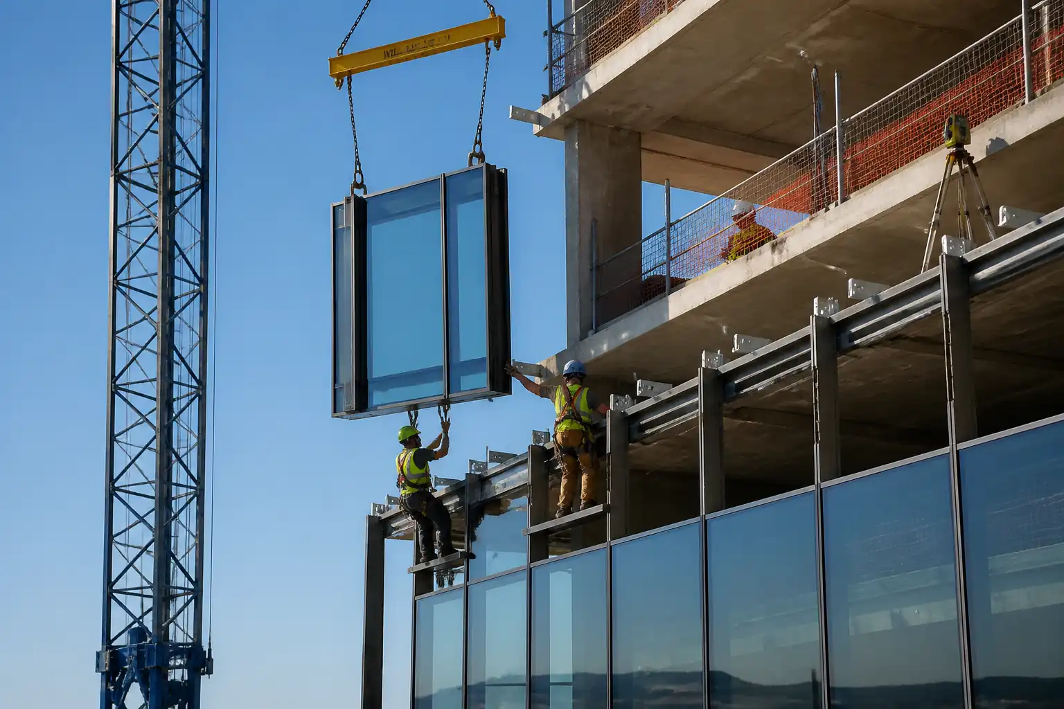
| 4 | Rigging gear inspection and trial lift | Inspect slings, shackles, spreaders; connect to chiller lifting lugs using softeners. Trial lift 100–300 mm to verify COG and balance. | Lifting Supervisor / Riggers | Rigging certificates, visual check |
| 5 | Control of environment for lift | Confirm wind below limit, no lightning, visibility adequate. Establish and enforce exclusion zone with banksmen. | Lifting Supervisor / HSE | Anemometer reading, permit check |
| 6 | Lift and place chiller on rooftop frame | Lift along planned path; no travel over personnel. Land softly on pre-positioned isolators or temporary seating pads as per design. | Crane Operator / Riggers | Banksman signals, landing control |
| 7 | Install and align spring isolators | If not pre-installed, jack and insert isolators at manufacturer locations; adjust to design free height and deflection; ensure snubber clearances. | MEP Supervisor | Level survey, isolator ID/ratings |
| 8 | Wind restraint installation | Install lateral restraints/tie-downs per drawings using approved anchors; respect edge distances/embeds; torque per manufacturer. | Structural/MEP Team | Anchor hole cleaning, embed measurement, torque check |
| 9 | Final positioning and clearance check | Verify service clearances around condenser coils, access panels, and airflow paths. | QA/QC / Vendor Rep | Measurement check |
| 10 | Piping connection preparation | Verify spool alignment with no imposed strain; install flexible connectors; support pipework to avoid load on chiller nozzles; fit strainers/valves as per P&ID. | MEP Supervisor / Pipefitters | Fit-up inspection |
| 11 | Make-up of grooved/flanged joints | Tighten per manufacturer sequence and torque; ensure gasket lubrication if required; witness markings applied. | Pipefitters / QA/QC | Torque check |
| 12 | Hydro/pressure test of CHW spools at chiller | Isolate test section; fill, vent air; pressurize to 1.3–1.5 × design (not less than specified minimum); hold per spec (e.g., 2 h). | MEP Supervisor / QA/QC | Gauge calibration, visual leak check |
| 13 | Initial flushing of connected spools (if in scope) | Flush at 1.5–2.0 m/s velocity to remove debris; clean strainers; reinstate. | MEP Supervisor | Flow verification, debris check |
| 14 | Electrical bonding and earthing check (if applicable) | Verify chiller base bonding continuity to building earth; confirm no temporary earth clamps left. | Electrical Supervisor | Continuity test |
| 15 | Final QA/QC and vendor pre-commissioning readiness | Joint inspection with vendor; verify isolator settings, restraints, labels, clearances, piping orientation/flow arrows, drain-downs. | QA/QC / Vendor Rep | Checklist review |
| 16 | Demobilization and as-built documentation | Remove crane and barriers; restore roof protections; submit as-builts, test certs, torque logs, anchor logs, warranties. | Site Manager / QA/QC | Area housekeeping check |
Health, Safety, and Environment (HSE) – Safety Controls
Principal Hazards and Controls
- Hazard: Crane overturning due to inadequate ground capacity or wind.
- Likely consequence: Multiple fatalities, severe property damage.
- Engineering/procedural control: Ground bearing pressure calculation and engineered mats; crane setup per load chart; live wind monitoring with stop-work thresholds; no lifting in lightning; level crane within tolerance.
- Required PPE: Hard hat with chin strap, hi-vis, safety boots, gloves, eye protection.
- Collective preventive measure: Exclusion zone barricades and spotters; taglines; no personnel under suspended loads.
-
Inspection/permit/supervision: Lifting Permit; pre-use inspection; third-party crane certification; Lifting Supervisor in control. [Verify per project HSE plan and local regulations]
-
Hazard: Dropped load during hoisting or landing.
- Likely consequence: Fatal injury, equipment damage.
- Engineering/procedural control: Rated rigging with valid certificates; redundant slinging where required; softeners at lugs; controlled taglines; trial lift to verify COG.
- Required PPE: As above plus cut-resistant gloves.
- Collective preventive measure: Hard barricades, spotters, overhead hazard signage, exclusion zone planning.
-
Inspection/permit/supervision: Rigging gear inspection log; banksman signaling protocol; stop-work authority.
-
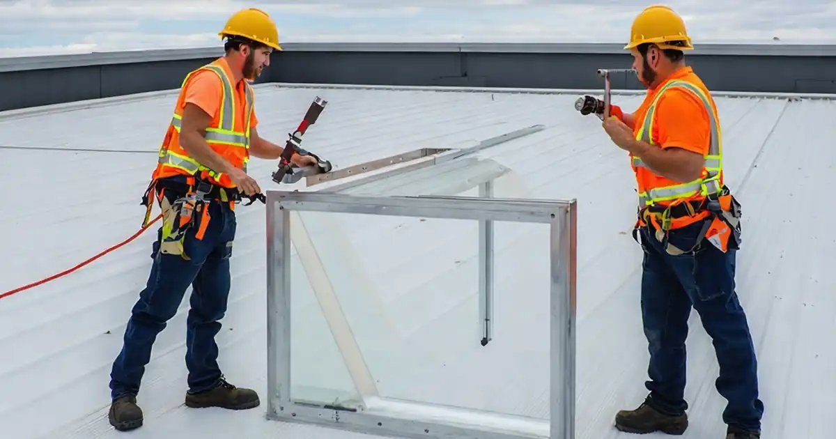
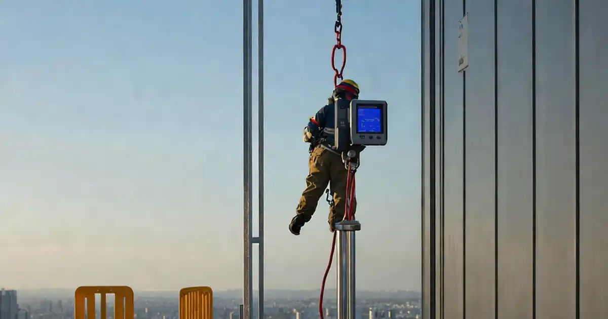
Hazard: Falls from height/roof edges and fragile skylights.
- Likely consequence: Serious injury or death.
- Engineering/procedural control: Guardrails, fixed edge protection, or lifeline systems; designated walkways; covers for skylights rated to load.
- Required PPE: Full-body harness with double lanyard when guardrails absent; non-slip footwear.
- Collective preventive measure: Temporary guardrails and warning lines ≥2 m from edge.
-
Inspection/permit/supervision: Work at Height Permit; daily inspection of fall protection by competent person.
-
Hazard: Wind gusts affecting suspended loads and rooftop handling.
- Likely consequence: Loss of control, collision, tip/roll of equipment.
- Engineering/procedural control: Defined wind hold points; postpone lifts if sustained wind > OEM limit; secure units immediately upon landing; use snubbers/restraints promptly.
- Required PPE: As standard.
- Collective preventive measure: Wind monitoring visible to lift team.
-
Inspection/permit/supervision: Weather log; Lifting Supervisor authorization before each pick.
-
Hazard: Manual handling and pinch/crush points during alignment.
- Likely consequence: Hand injuries, fractures.
- Engineering/procedural control: Use pry bars/jacks, never hands between base and frame; lift with mechanical aids; keep clear communication.
- Required PPE: Impact-resistant gloves, eye protection.
- Collective preventive measure: Team lifts with designated lead; exclusion of bystanders.
-
Inspection/permit/supervision: Supervisor oversight; toolbox talk on pinch points.
-
Hazard: Drilling/anchoring creating dust and noise; chemical exposure from adhesives.
- Likely consequence: Respiratory irritation, silica exposure, dermatitis.
- Engineering/procedural control: HEPA dust extraction; wet suppression where allowed; low-VOC anchors; follow SDS; mixing/installation per ETA/ESR.
- Required PPE: FFP2/FFP3 respirator, eye protection, nitrile gloves, hearing protection.
- Collective preventive measure: Local exhaust, noise barriers if needed.
-
Inspection/permit/supervision: COSHH/chemical permit where required; SDS available; HSE inspections.
-
Hazard: Electrical energization during checks.
- Likely consequence: Electric shock, arc flash.
- Engineering/procedural control: LOTO for any circuits; verify isolation; use qualified electrician; test-before-touch.
- Required PPE: Electrically rated gloves, arc-rated clothing where relevant.
- Collective preventive measure: Lock boxes, permit-to-work.
-
Inspection/permit/supervision: Electrical work permit; supervision by Electrical Supervisor.
-
Hazard: Heat stress/UV exposure during rooftop work.
- Likely consequence: Dehydration, heat exhaustion.
- Engineering/procedural control: Work-rest cycles, hydration stations, shade, schedule in cooler hours.
- Required PPE: Sun protection, cooling vests if needed.
- Collective preventive measure: Environmental monitoring; buddy system.
-
Inspection/permit/supervision: HSE monitoring; first-aid readiness.
-
Hazard: Adverse weather (rain/ice) causing slips; lightning.
- Likely consequence: Slips/falls, electrocution.
- Engineering/procedural control: Suspend work during lightning within defined radius; anti-slip mats; housekeeping.
- Required PPE: Slip-resistant boots, rain gear.
- Collective preventive measure: Access control to wet areas.
- Inspection/permit/supervision: Weather watch; permit pause/restart protocol.
Environmental Controls
- Noise: Schedule lifts and drilling within permitted hours; use acoustic shrouds on compressors if running; maintain equipment to minimize noise.
- Dust: HEPA extraction on drilling; wet suppression where compatible with roof materials; cover coils during dusty works to prevent fouling.
- Spill prevention: Spill kits at crane and workface; drip trays under hydraulic couplings; refueling in designated area with secondary containment; immediate cleanup and reporting.
- Waste management: Segregate packaging, metal offcuts, spent cartridges; dispose per local regulations; maintain waste transfer notes.
- Roof protection: Lay protection mats over membranes; avoid point loads; no hot works on membrane unless authorized; reinstate waterproofing after penetrations.
- Stormwater protection: Prevent debris from entering roof drains; use inlet filters; no discharge of test water without approval; treat/flocculate if chemically dosed.
- Air quality: Avoid idling plant; ensure adhesives/solvents are low-VOC where feasible; store chemicals in ventilated, bunded areas.
- Wildlife/neighbor impacts: Control lighting spill at night; communication with building occupants before lifts.
QA/QC Requirements
- Submittals/Approvals: Vendor data (weights, COG, lifting points), isolator data (ratings, deflection), anchor ETA/ESR, torque tables, valves/fittings approvals, lift plan, crane certs, welding/bolting procedures (if any), calibration certs.
- Hold/Witness Points: Refer to ITP. Typical hold points include crane setup verification, first unit isolation setting, first anchor installation, pressure test, and final pre-commissioning walkdown.
- Tolerances/Criteria:
- Chiller base level: ±2 mm/m; ±4 mm overall across base [Verify per manufacturer].
- Isolator deflection: within ±10% of calc; snubber gaps per vendor; all springs share load (height variance ≤ 3 mm typical) [Verify].
- Anchor installation: embedment and edge distances per design; torque per manufacturer; proof testing where specified.
- Piping: flange/grooved joint torque per manufacturer; nozzle misalignment ≤ 1 mm/100 mm; supports installed to prevent load on chiller nozzles.
- Hydro/pressure test: 1.3–1.5 × design, minimum duration typically 2 h; zero leaks; pressure drop ≤ 1% after stabilization [Verify].
- Inspection Records: Delivery inspection, rigging inspection, crane setup checklist, survey/level reports, isolation setting log, torque logs, anchor installation log and proof test reports, pressure test certificates, flushing reports, as-built markups, NCRs/CCRs if any.
- Nonconformance: Document via NCR; define corrective action; re-test as applicable; update as-builts.
- Documentation Handover: O&M manuals, warranties, vendor startup checklist, as-built drawings, ITP with signed records.
Attachments
- Approved Lift Plan with rigging calculations and crane load charts
- Structural calculations and rooftop frame/shop drawings
- Manufacturer installation manuals for chillers and isolators
- Anchor ETA/ESR reports and installation procedures
- Torque tables for bolts/couplings; calibrated tool certificates
- Pressure test procedure and certificates; gauge calibration
- HSE documents: JSA/RA, Permits, Toolbox Talks, Emergency Plan
- As-built drawings and survey reports; photos of critical stages
This content is a read-only public reference. Download or customize to get an editable version.
ITP preview
The first inspection activities from the linked ITP for Method Statement: Installation of Air-Cooled Chillers on Rooftop Structural Steel Frames:
| Activity | Inspection / Test | Acceptance Criteria | Responsibility | Record |
|---|---|---|---|---|
| Document approvals (drawings, lift plan, calculations) | Verification of approvals prior to works | All required approvals in place and current | PM / QA-QC | Approval matrix, transmittals |
| Crane certification and setup verification | Check certs, load chart, pad/outrigger mats, level | Compliant with lift plan and OEM; level within tolerance | Lifting Supervisor / QA-QC | Crane setup checklist |
| Rigging inspection and trial lift | Visual inspection, WLL check, trial lift | Rigging certified; balanced lift; taglines fitted | Lifting Supervisor | Rigging inspection form |
Showing 3 of 14 inspection activities. View full ITP →
Related Inspection and Test Plan
An Inspection and Test Plan (ITP) is available for Method Statement: Installation of Air-Cooled Chillers on Rooftop Structural Steel Frames. The ITP defines the inspection activities, acceptance criteria, hold and witness points, responsible parties, and records required to verify the work described in this method statement.
View the Method Statement: Installation of Air-Cooled Chillers on Rooftop Structural Steel Frames ITP →Frequently asked questions
Continue with related Quollnet resources connected to this method statement.