Method Statement: Precast Concrete Beam Erection Works – Method Statement
AI-assisted method statement with matching ITP, PDF download, and Excel export.
More than a static template
Unlike a downloadable Word or PDF template, this method statement is an AI-assisted editable starting point connected directly to a matching Inspection and Test Plan. Every section is structured, project-adaptable, and ready to export.
- AI-assisted drafting — Customize every section with AI for your specific project scope.
- Linked ITP — A matching inspection and test plan is generated alongside the method statement.
- Multiple export formats — Download as a formatted PDF or editable Excel spreadsheet.
- Editable starting point, not a final document — Review, verify, and adjust all content against your project requirements before use.
Static template vs. Quollnet workflow
| Feature | Static template | Quollnet |
|---|---|---|
| Project-specific content | Manual fill-in required | AI-assisted customization |
| Linked ITP | Separate document, no link | Matching ITP included |
| Export formats | Usually PDF only | PDF and Excel |
| Structured sections | Free-form layout | 13 standardized sections |
| Saved to your account | Local file only | Cloud-saved, reusable |
| Content accuracy | You verify everything | AI-assisted, you still verify |
| Cost | Often free but time-intensive | Free to customize and download |
What you can customize
When you save this method statement to your account, every section becomes editable. The following 13 sections are included:
- Scope — Defines the activity and its boundaries.
- References — Standards, specifications, and drawings.
- Responsibilities — Roles and accountabilities.
- Resources — Labour, plant, and equipment summary.
- Materials — Materials and compliance requirements.
- Equipment — Tools and equipment details.
- Prerequisites — Hold points and pre-conditions.
- Method sequence — Step-by-step construction sequence.
- Safety controls — HSE risk controls and PPE.
- Environmental controls — Environmental mitigation measures.
- QA/QC — Quality inspection and test requirements.
- ITP — Inspection and Test Plan table (has its own page).
- Attachments — Referenced drawings and documentation.
Why this method statement is used
This method statement is used to define and communicate the approved procedure for carrying out method statement: precast concrete beam erection works on site. It ensures the work is planned in advance, the correct resources and controls are in place, and all personnel understand responsibilities, sequence, quality requirements, and safety controls before work begins. It aligns site execution with the documented scope and acceptance expectations.
Who uses this method statement
This method statement is used by contractors, site supervisors, project engineers, QA/QC engineers, HSE officers, consultants, and client representatives. It serves as a shared reference for planning, execution, supervision, inspection, and approval of the activity on site.
When it is prepared and submitted
The method statement is prepared before the work activity starts and submitted as part of the pre-construction documentation package for review and approval.
Who reviews or approves it
The method statement is usually submitted to the client representative, consultant, resident engineer, or project management consultant for review and approval before the work commences.
Important approval note
This method statement is an AI-assisted editable starting point, not a pre-approved document. Before use on any project, all content must be reviewed and approved by the relevant parties (superintendent, principal contractor, or client representative) in accordance with your contract and project quality plan.
For example: if your specification requires a departure from a referenced standard, that departure must be documented and approved separately — this method statement will not capture that automatically. Always verify against your applicable drawings, specifications, and regulatory requirements.
Method statement content
Scope
Summary
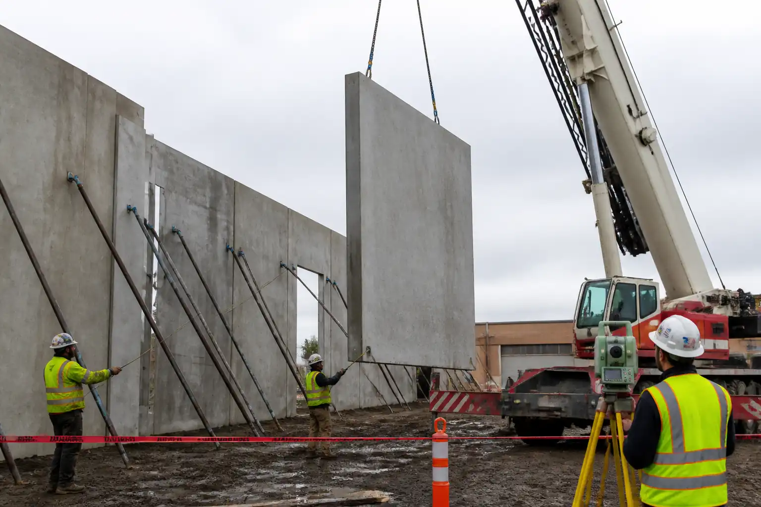
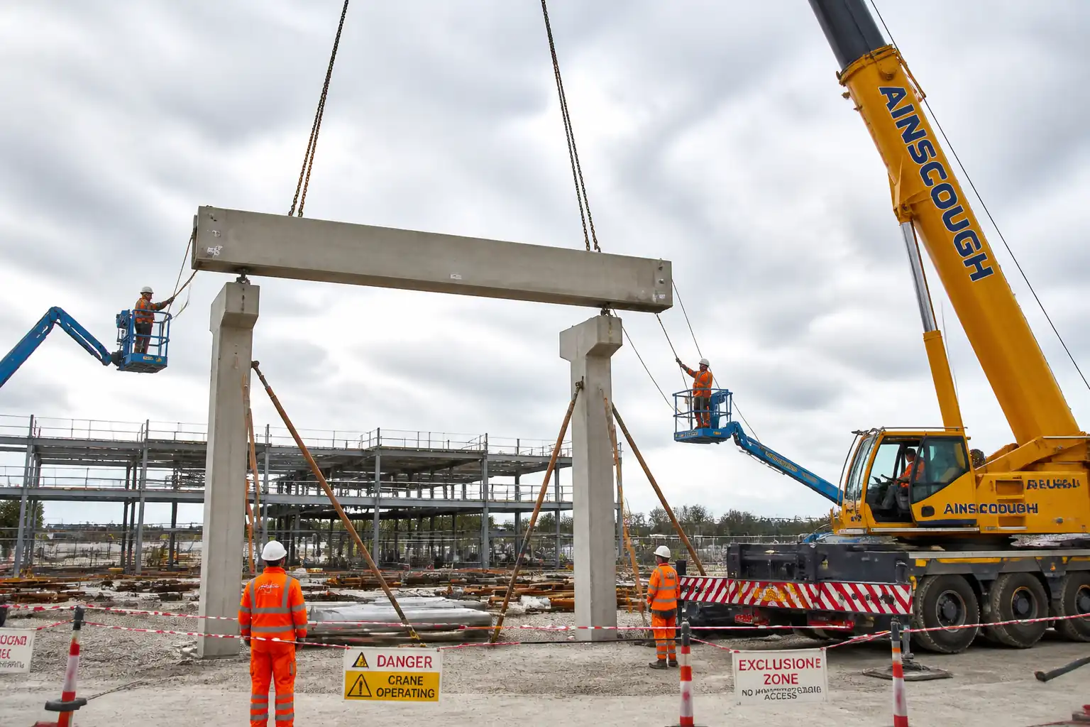
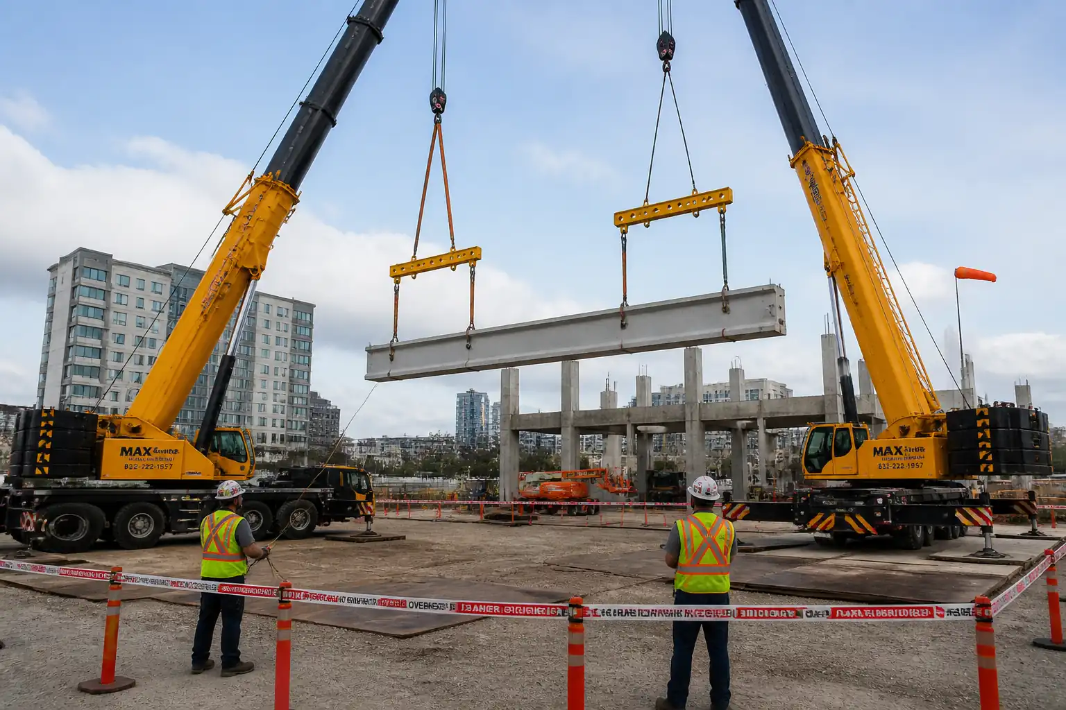
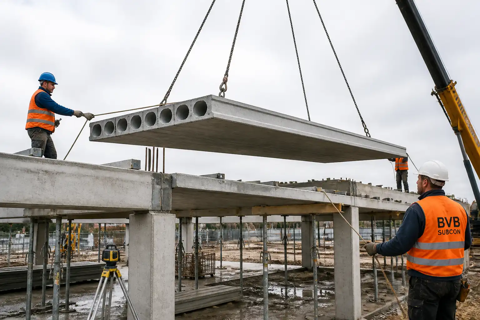
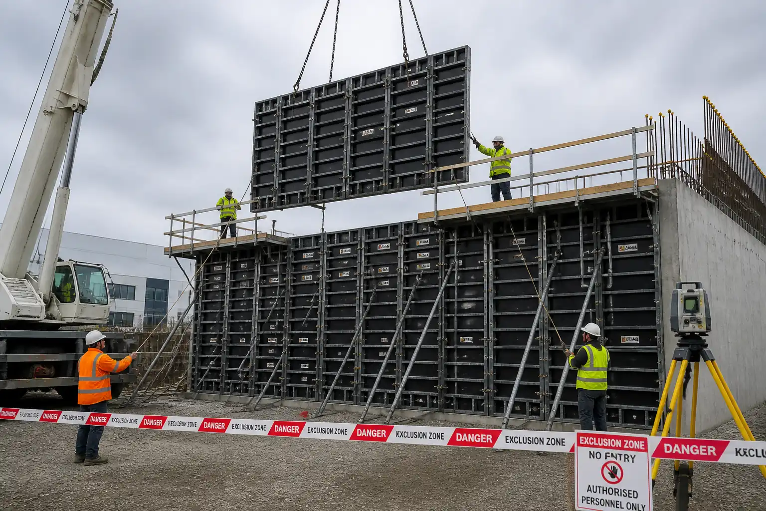
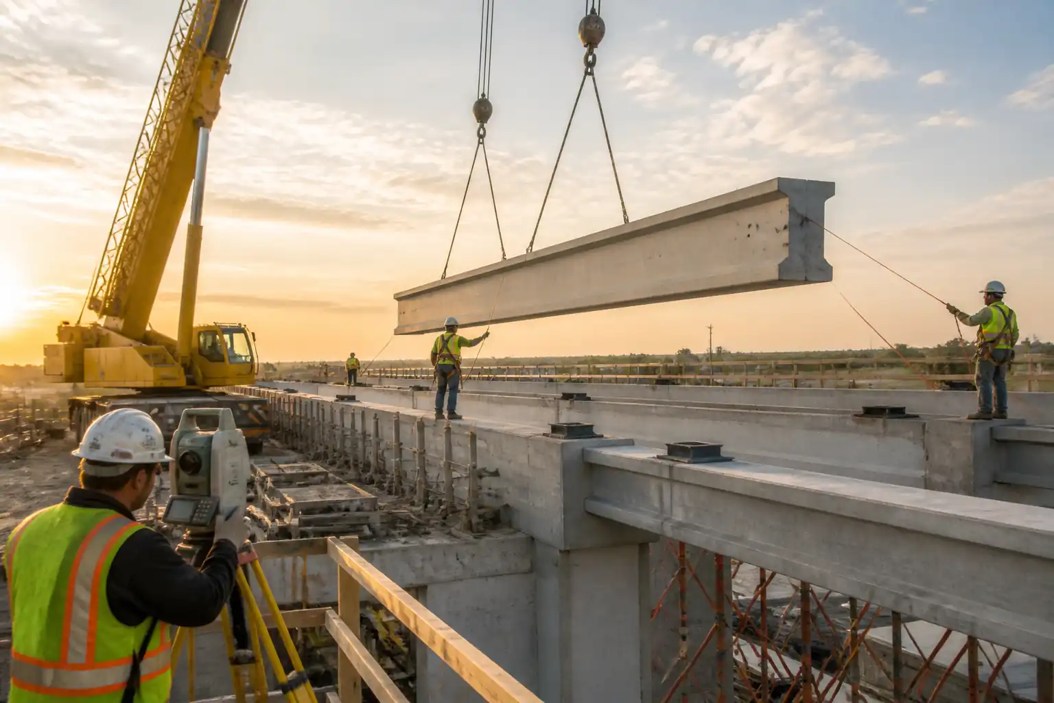
This method statement covers the complete sequence for the erection of precast concrete beams, from pre-erection checks through lifting, setting on bearings, temporary restraint, alignment and connection detailing, grouting, curing, inspection, and handover. It integrates coordination with adjacent trades and defines QA/QC and HSE controls.
Included Activities
- Receipt, inspection, and handling of precast beams.
- Lifting gear certification review and pre-use inspections.
- Bearing setting-out, level/slope verification, and shimming.
- Crane setup, trial lift, controlled hoisting, placement, and seating.
- Installation of temporary bracing/restraints and edge protection.
- Survey alignment checks (line, level, plumb, camber) and adjustments.
- Connection works: dowels, shear keys, pockets, bearing fixity components, and (if specified) welding.
- Precision non-shrink grouting to bearings and connection pockets; curing and strength verification.
- ITP hold/witness points, as-built survey, and release of temporary works.
- Coordination with adjacent trades (MEP, decking, slab/topping, façade/edge protection).
Exclusions
- Design of precast elements and permanent connections (by Designer/Precaster unless noted).
- Permanent works design of bearings and structural adequacy (by Designer).
- Category 2/3 checks of temporary works design (by independent checker) [Verify per project specifications].
Key Tolerances (typical, to be verified)
- Bearing level tolerance: ±3 mm between paired seats; cross-fall per drawing [Verify].
- Beam longitudinal position: ±10 mm; transverse: ±6 mm [Verify].
- Differential level at bearings: ≤5 mm [Verify].
- Beam rotation/plumb: ≤0.5° [Verify].
- Grout thickness under bearings: 20–50 mm [Verify].
- Minimum grout strength before releasing temporary restraints: ≥70% of 28-day strength or per designer [Verify].
All values to be confirmed against project specifications, approved shop drawings, and precaster erection drawings.
References
| Document Type | Reference / Number | Revision | Notes |
|---|---|---|---|
| Standard | BS EN 13670: Execution of Concrete Structures (Erection tolerances and execution) | ||
| Standard | BS EN 1337 (all relevant parts): Structural Bearings | ||
| Standard | PCI Design Handbook / Erector's Manual (latest ed.) [Verify edition] | Precast erection tolerances, handling, bracing | |
| Standard | BS 5975: Temporary works procedures and the permissible stress design of falsework | Temporary works management, TWC/TWS roles, permits | |
| Standard | EN 13000: Cranes — Mobile cranes (safety) | ||
| Standard | BS EN 1492 (Textile slings), BS EN 818 (Chain slings), BS EN 13155 (Non-fixed lifting attachments), ASME B30.9 (Slings), ASME B30.26 (Rigging hardware) [Verify per jurisdiction] | Rigging selection, use, inspection criteria | |
| Standard | ISO 9927-1: Cranes — Inspections | ||
| Standard | ACI 117/ACI 318 (tolerances/structural concrete) [if applicable] | ||
| Standard | ASTM C1107: Non-shrink Grout; ASTM C939: Flow of Grout; EN 1504-3 (R4 repair mortars) [Verify product standard] | Grout performance and testing | |
| Project Doc | Project Specifications, Approved Shop/Erection Drawings, Lift Plan, Method Statements, ITP, MSDS/SDS |
Responsibilities
| Role | Responsibility | Name / Party |
|---|---|---|
| Project Manager | Overall implementation of method, resource allocation, compliance to specs; approves temporary works and permits to load/strike per BS 5975 | Main Contractor |
| Lifting Supervisor/Appointed Person | Leads lifting operations, coordinates with rigging crew and crane operator, ensures signal-only protocol, enforces exclusion zone | Main Contractor |
| Temporary Works Coordinator (TWC) | Design/checks of temporary works; issues permits to load/strike; ensures bracing adequacy and stability until permanent capacity achieved | Main Contractor |
| Site Engineer/Surveyor | Survey control, setting out, bearing level verification, as-built surveys, tolerance checks | Main Contractor |
| Rigger | Performs pre-use inspections, rigging/deration calculations, sling angle checks, controls taglines | Main Contractor |
| Crane Operator | Operates crane per lift plan; verifies load charts, radius, and outrigger setup; halts works if unsafe | Crane Subcontractor |
| QA/QC Engineer | Witness/hold point inspections, approves ITP stages, verifies material certificates and test results | Main Contractor |
| Engineer/Consultant | Reviews/approves shop drawings, method, ITP; inspects hold points; authorizes release of temporary works | Employer/Engineer |
Resources
| Resource Type | Description | Quantity | Remarks |
|---|---|---|---|
| Personnel | 1 | ||
| Personnel | 2–4 [Verify] | ||
| Personnel | 1 per crane | ||
| Personnel | 1 | ||
| Personnel | 2–6 [Verify] | ||
| Personnel | 2–4 [Verify] |
Materials
| Material | Specification / Grade | Quantity | Remarks |
|---|---|---|---|
| Precast concrete beams | Concrete grade, dimensions, weight, inserts per approved shop drawings [Verify] | ||
| Structural bearings | BS EN 1337 compliant; hardness, dimensions, rotation/translation capacity per design [Verify] | ||
| Stainless/galvanized steel shims/packers | Grade and thickness per design; corrosion protection [Verify] | ||
| Non-shrink cementitious grout | ASTM C1107 Type A/C or EN 1504-3 R4; 28-day f'c ≥ 50 MPa [Verify]; bleeding ≤0.5%; flow per ASTM C939 [Verify] | ||
| Temporary bracing/restraint system | Designed/calculated per BS 5975; capacity for wind/erection loads incl. partial factors [Verify] | ||
| Reinforcement, dowels, anchorages, weld plates | Grade per drawings; welding per ISO 15614/EN 1090 if applicable [Verify] |
Equipment
| Equipment | Capacity / Type | Quantity | Inspection Required |
|---|---|---|---|
| Mobile crane | Rated capacity ≥ 1.25 × max lifted load at working radius [Verify] | Thorough exam certificate valid [Verify] | |
| Slings (chain/textile/wire) & shackles | WLL ≥ factored load; angle deration applied [Verify] | Certs ≤6 months (lifting accessories) or per regulation; pre-use check | |
| Spreader beam/lifting beam | ≥ max lift load with factor [Verify] | Certificate and ID tag | |
| Digital level/auto level & staff; total station/laser | ±1 mm accuracy or better [Verify] | Calibration certificate valid | |
| Torque wrench | Range per anchor spec | Calibration certificate valid | |
| Grout mixer/pump, flow cone, cube molds | As per grout supplier | Cleanliness check; verification of molds per ASTM C109 | |
| Taglines, radios, edge protection, MEWP/boom lift | Suitable reach/height | MEWP inspection; harness and anchor points verified |
Prerequisites
Approvals & Documentation
- Approved shop/erection drawings, lifting plan, method statement, ITP, and Risk Assessment.
- Temporary Works design for bracing/restraints and bearing seating/shimming method; Category check as required by BS 5975 [Verify].
- Material approvals: bearings, grout, anchors, braces; delivery dockets and certificates.
Site Preparation & Survey
- Setting-out benchmarks established; bearing seats surveyed and marked. Bearing levels verified before delivery.
- Access, crane pad/working radius established with confirmed ground bearing capacity (GBC) calculations and mats installed. GBC ≥ applied outrigger pressure with factor of safety ≥ 1.5 [Verify].
- Exclusion zones delineated; traffic and pedestrian management in place.
Utilities, Permits & Weather
- Underground/overhead utilities identified; power line clearance maintained per local regulations [Verify].
- Permits: Lifting, working at height, hot work (if welding), temporary works permit to load/strike, crane operation.
- Weather limits: Max wind speed at load height typically ≤ 9–12 m/s for long beams; stop for lightning, heavy rain reducing visibility or crane stability [Verify].
Equipment & Personnel Readiness
- Crane and lifting accessories: valid third-party certifications; color-coding current.
- Calibrations: survey instruments, torque wrenches within validity.
- Pre-task briefing/Toolbox Talk and lift rehearsal (dry run) with all involved parties.
Coordination
- Adjacent trades notified; sequencing agreed for decking, topping concrete, MEP penetrations, and façade edges.
- Precaster provides handling points, beam weights/CG, recommended slinging and brace points.
Method Sequence
| Step | Activity | Description | Responsibility | Inspection / Hold Point |
|---|---|---|---|---|
| 1 | Pre-erection coordination & documentation | Confirm approvals; review lift plan, rigging, temporary works designs; conduct pre-start meeting and TBT; verify weather and permits | Project Manager / Lifting Supervisor / TWC | Document check |
| 2 | Bearing installation & survey | Install bearings/shims per drawings; ensure bearing seating surfaces are sound, clean, and at correct elevation/slope; mark axes | Site Engineer / Precast Installer | Survey check |
| 3 | Crane setup | Position crane per lift plan; set outriggers on mats; verify radius and load chart; establish exclusion zone; comms check | Crane Operator / Lifting Supervisor | Pre-use inspection |
| 4 | Lifting gear verification | Check slings, shackles, spreader; confirm WLL ≥ required; check angles, D/d ratios; attach to certified inserts/lifting points | Rigger / Lifting Supervisor | Visual and document check |
| 5 | Trial lift & balance check | Lift beam 100–200 mm to verify balance and rigging; adjust sling lengths as needed | Crane Operator / Rigger | Supervisor observation |
| 6 | Hoisting & positioning | Hoist under control using taglines; align with setting-out marks; lower slowly onto bearings without impact | Crane Operator / Banksman / Rigger | Banksman oversight |
| 7 | Temporary restraint installation | Install designed braces/props before releasing slings; fix anchors and apply specified torque; ensure stability for wind loads | Installer / TWC | Hold point (temporary stability) |
| 8 | Alignment survey & adjustments | Check line, level, plumb, camber; adjust shims/packers as required; record as-built | Site Engineer/Surveyor | Survey verification |
| 9 | Connection detailing | Install dowels, shear keys, pocket reinforcement; prepare and, if specified, weld plates per approved WPS with qualified welders; clean and prepare interfaces | Installer / Welding Subcontractor (if applicable) | Witness/hold for welding and reinforcement |
| 10 | Grouting of bearings and pockets | Surface prep (SSD), mix grout per datasheet; place from one side to avoid air entrapment; maintain head; install vents; cure per supplier | Grouting Crew / QA | Witness point (pre-pour and during) |
| 11 | Curing & release of temporary works | Cure grout; verify strength (≥70% of 28-day or per design) before removing braces; TWC issues permit to strike | TWC / QA / Engineer | Hold point (release) |
| 12 | Final inspection & handover | Complete snagging; verify tolerances, connections, grout finish; update as-builts; handover to next trades | QA/QC / Engineer | Final inspection |
Health, Safety and Environment - Safety Controls
Task-specific Hazards and Controls
- Hazard: Crane overturning due to inadequate ground bearing or improper outriggers.
- Likely consequence: Catastrophic collapse, fatal injury.
- Engineering/procedural control: Engineer GBC assessment; timber/mats sized to limit ground pressure; crane setup per EN 13000; level within manufacturer limits; no slewing over soft ground; weather limits enforced.
- Required PPE: Hard hat, high-vis, safety boots, gloves.
- Collective measures: Exclusion zone with barriers; banksman control; no personnel under suspended loads.
-
Inspection/permit: Crane daily checklist; third-party certs; lifting permit; TWC verification.
-
Hazard: Suspended load strike or dropped beam.
- Consequence: Serious injury/fatality, structural damage.
- Controls: Dedicated banksman; taglines on all long beams; single point of command; rigging verification (WLL, angles, pins); trial lift at 100–200 mm; stop-work authority.
- PPE: Hard hat with chin strap, gloves, eye protection.
- Collective: Exclusion zone sized to radius + 10 m [Verify]; spotters.
-
Inspection/permit: Pre-use rigging inspection; lifting permit; toolbox talk.
-
Hazard: Working at height on narrow beams/edges.
- Consequence: Falls from height.
- Controls: Edge protection or fall restraint; use MEWP for access; no hopping between beams; install temporary walkways; anchor points certified.
- PPE: Full body harness with double lanyard where MEWP/restraint used; non-slip boots.
- Collective: Guardrails, safety nets where feasible [Verify].
-
Inspection/permit: Work at height permit; MEWP inspection tag.
-
Hazard: Beam instability before permanent fixity.
- Consequence: Toppling, collapse.
- Controls: Bracing per TWD; do not release slings until braces installed; verify torque; wind monitoring; staged loading limits.
- PPE: Standard site PPE.
- Collective: Permit to load/strike; warning signage.
-
Inspection/permit: TWC inspection; hold point before release.
-
Hazard: Pinch/crush during seating and shimming.
- Consequence: Hand injuries, fractures.
- Controls: Keep hands clear; use pry bars and remote shimming tools; slow lowering; communication protocol.
- PPE: Cut-resistant gloves, eye protection.
- Collective: Exclusion zones and spotter.
-
Inspection/permit: Supervisor oversight; JSA briefing.
-
Hazard: Overhead services proximity (power lines).
- Consequence: Electrocution, arc flash.
- Controls: Confirm safe approach distance; de-energize or isolate if within limits; goalposts and signage.
- PPE: Dielectric gloves if required; standard PPE.
- Collective: Physical barriers; banksman.
-
Inspection/permit: Permit to work near HV; utility owner's consent [Verify].
-
Hazard: Hot works for welded connections.
- Consequence: Burns, fire, fume inhalation.
- Controls: Hot work permit; fire watch; screens; extraction/ventilation; approved WPS; flashback arrestors.
- PPE: Welding hood, FR clothing, gloves, eye/face protection.
- Collective: Fire extinguishers; spark containment.
-
Inspection/permit: Hot work permit; welder qualifications.
-
Hazard: Manual handling of shims and braces.
- Consequence: Strains, musculoskeletal injuries.
- Controls: Use mechanical aids; team lifts; weight labeling.
- PPE: Gloves, back support where approved.
- Collective: Trolleys/lifters available.
- Inspection/permit: Manual handling training.
[Verify per project HSE plan and local regulations].
Environmental Controls
Environmental Risks and Controls
- Cementitious grout washout and alkaline wastewater
- Impact: High pH discharge harming drainage and waterways.
- Controls: Dedicated washout containers; no discharge to surface/groundwater; pH neutralization per plan; spill kits at point of use.
-
Monitoring: Visual checks and pH testing [Verify].
-
Dust/noise from drilling, cutting, or impact tools
- Impact: Nuisance to neighbors; worker exposure.
- Controls: Wet cutting or local extraction; low-noise tools; time restrictions; noise barriers where needed.
-
Monitoring: Noise readings per local limits; RPE as last resort.
-
Fuel/ hydraulic oil spills from crane/MEWP
- Impact: Soil and water contamination.
- Controls: Drip trays under parked plant; spill kits; regular plant inspection; refueling on impervious surface.
-
Monitoring: Daily plant checklists.
-
Waste management of packaging, grout bags, scrap steel
- Impact: Litter, unnecessary landfill.
- Controls: Segregate per waste streams; recycle metals and clean pallets; licensed disposal.
-
Monitoring: Waste transfer notes; monthly summaries.
-
Light pollution for night works
- Impact: Community nuisance, ecology.
-
Controls: Directional LED lighting; shielded fittings; curfew compliance.
-
Vibration impact on sensitive adjacent structures
- Impact: Cosmetic damage, complaints.
- Controls: Minimize percussive methods; monitor where specified; maintain communication with stakeholders.
[Verify per project environmental management plan].
QA/QC Requirements
Controls, Tests, and Records
- Material certificates: Bearings (EN 1337), grout (ASTM C1107/EN 1504), lifting accessories (EN/ASME), braces and anchors.
- Calibration: Survey instruments and torque wrenches valid; records on file.
- Tolerances: As listed in Scope or drawings. Any exceedance triggers NCR and corrective action plan.
- Inspections: Hold/witness points per ITP at bearings survey, temporary stability, grouting, and release of braces.
- Grout QA: Batch records including ambient and grout temperature, water ratio, flow (ASTM C939) [Verify], start/finish times, cube sampling (ASTM C109) with frequencies (e.g., 3 cubes per batch or per 5 m² of bearing area) [Verify].
- Welding QA (if applicable): WPS/WPQR approval; welder quals; visual inspection; NDT per spec (e.g., MT/UT) [Verify].
- As-built: Survey of beam positions/levels; camber records; marked-up drawings.
- Permits: Permit to load and strike signed by TWC.
- Records retention: Minimum duration per contract (typically project duration + 12 years) [Verify].
Attachments
- Pre-erection checklist (bearings, drawings, permits)
- Sample Lift Plan (crane configuration, load chart, rigging diagram, exclusion zone)
- Rigging inspection checklist and color-coding chart
- Bearing schedule and survey record template
- Temporary Works Permit to Load/Strike templates
- Grout QA log sheet and cube register
- Welding WPS/WPQR templates (if applicable)
- As-built survey template and tolerance checklist
- Emergency response plan for lifting operations
This content is a read-only public reference. Download or customize to get an editable version.
ITP preview
The first inspection activities from the linked ITP for Method Statement: Precast Concrete Beam Erection Works:
| Activity | Inspection / Test | Acceptance Criteria | Responsibility | Record |
|---|---|---|---|---|
| Pre-erection documentation check | Review approvals, lift plan, TWD, permits, certificates | All approvals current; risk assessments and permits signed; certificates valid | QA/QC Engineer | Checklist; copies of approvals |
| Bearing installation & survey | Level/position survey using calibrated instrument | Level within ±3 mm between seats; alignment within ±6–10 mm; surfaces clean/dry [Verify] | Site Engineer / Engineer (Witness) | Survey report; photos; bearing schedule |
| Rigging and lifting gear inspection | Visual check of slings/shackles/spreader; certificate review; sling angle calculation | WLL adequate with deration; no defects; certs in date | Lifting Supervisor | Rigging log; pre-use checklist |
Showing 3 of 10 inspection activities. View full ITP →
Related Inspection and Test Plan
An Inspection and Test Plan (ITP) is available for Method Statement: Precast Concrete Beam Erection Works. The ITP defines the inspection activities, acceptance criteria, hold and witness points, responsible parties, and records required to verify the work described in this method statement.
View the Method Statement: Precast Concrete Beam Erection Works ITP →Frequently asked questions
Continue with related Quollnet resources connected to this method statement.