Method Statement: Precast Concrete Wall Panel Installation – Method Statement
AI-assisted method statement with matching ITP, PDF download, and Excel export.
More than a static template
Unlike a downloadable Word or PDF template, this method statement is an AI-assisted editable starting point connected directly to a matching Inspection and Test Plan. Every section is structured, project-adaptable, and ready to export.
- AI-assisted drafting — Customize every section with AI for your specific project scope.
- Linked ITP — A matching inspection and test plan is generated alongside the method statement.
- Multiple export formats — Download as a formatted PDF or editable Excel spreadsheet.
- Editable starting point, not a final document — Review, verify, and adjust all content against your project requirements before use.
Static template vs. Quollnet workflow
| Feature | Static template | Quollnet |
|---|---|---|
| Project-specific content | Manual fill-in required | AI-assisted customization |
| Linked ITP | Separate document, no link | Matching ITP included |
| Export formats | Usually PDF only | PDF and Excel |
| Structured sections | Free-form layout | 13 standardized sections |
| Saved to your account | Local file only | Cloud-saved, reusable |
| Content accuracy | You verify everything | AI-assisted, you still verify |
| Cost | Often free but time-intensive | Free to customize and download |
What you can customize
When you save this method statement to your account, every section becomes editable. The following 13 sections are included:
- Scope — Defines the activity and its boundaries.
- References — Standards, specifications, and drawings.
- Responsibilities — Roles and accountabilities.
- Resources — Labour, plant, and equipment summary.
- Materials — Materials and compliance requirements.
- Equipment — Tools and equipment details.
- Prerequisites — Hold points and pre-conditions.
- Method sequence — Step-by-step construction sequence.
- Safety controls — HSE risk controls and PPE.
- Environmental controls — Environmental mitigation measures.
- QA/QC — Quality inspection and test requirements.
- ITP — Inspection and Test Plan table (has its own page).
- Attachments — Referenced drawings and documentation.
Why this method statement is used
This method statement is used to define and communicate the approved procedure for carrying out method statement: precast concrete wall panel installation on site. It ensures the work is planned in advance, the correct resources and controls are in place, and all personnel understand responsibilities, sequence, quality requirements, and safety controls before work begins. It aligns site execution with the documented scope and acceptance expectations.
Who uses this method statement
This method statement is used by contractors, site supervisors, project engineers, QA/QC engineers, HSE officers, consultants, and client representatives. It serves as a shared reference for planning, execution, supervision, inspection, and approval of the activity on site.
When it is prepared and submitted
The method statement is prepared before the work activity starts and submitted as part of the pre-construction documentation package for review and approval.
Who reviews or approves it
The method statement is usually submitted to the client representative, consultant, resident engineer, or project management consultant for review and approval before the work commences.
Important approval note
This method statement is an AI-assisted editable starting point, not a pre-approved document. Before use on any project, all content must be reviewed and approved by the relevant parties (superintendent, principal contractor, or client representative) in accordance with your contract and project quality plan.
For example: if your specification requires a departure from a referenced standard, that departure must be documented and approved separately — this method statement will not capture that automatically. Always verify against your applicable drawings, specifications, and regulatory requirements.
Method statement content
Scope
Description
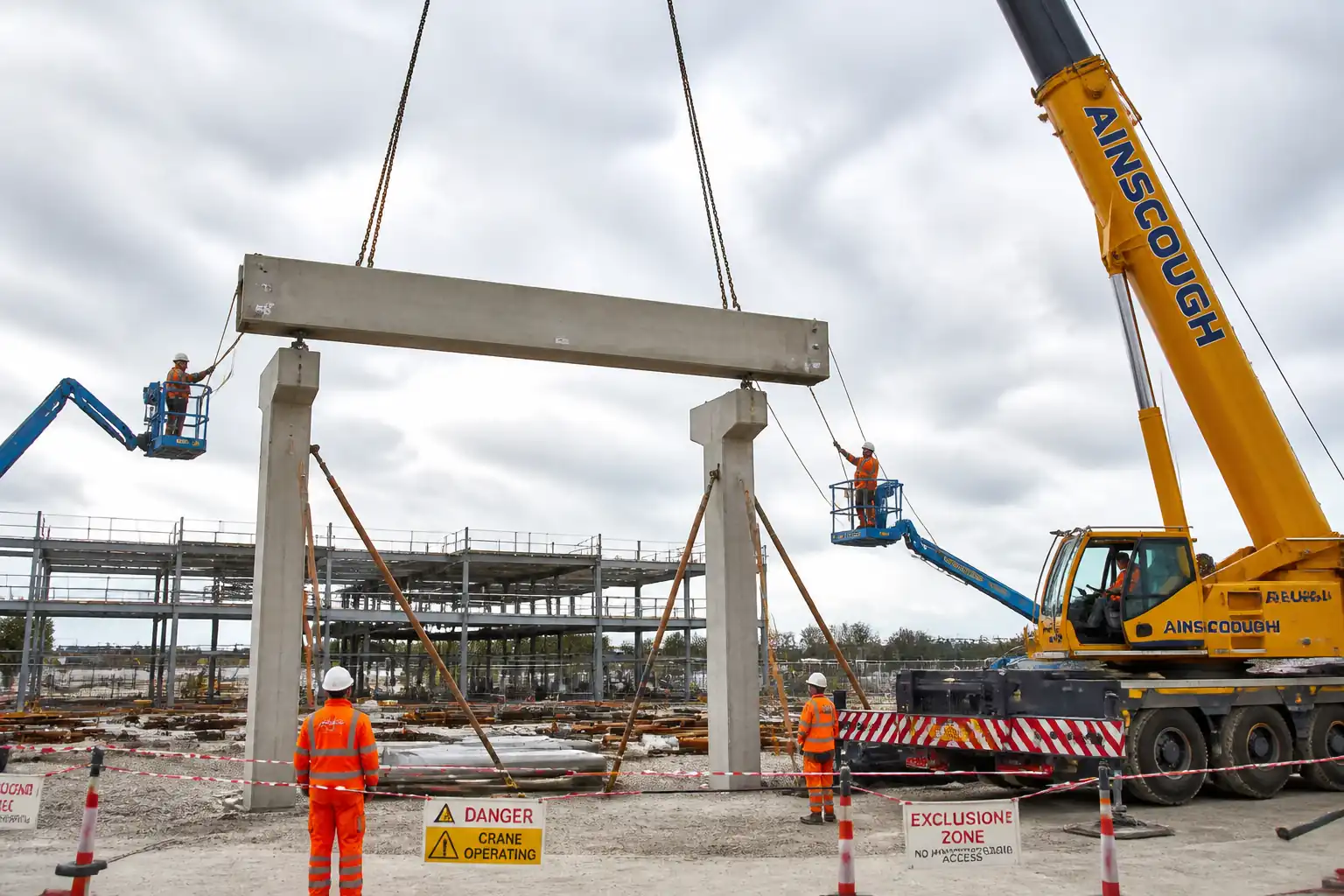
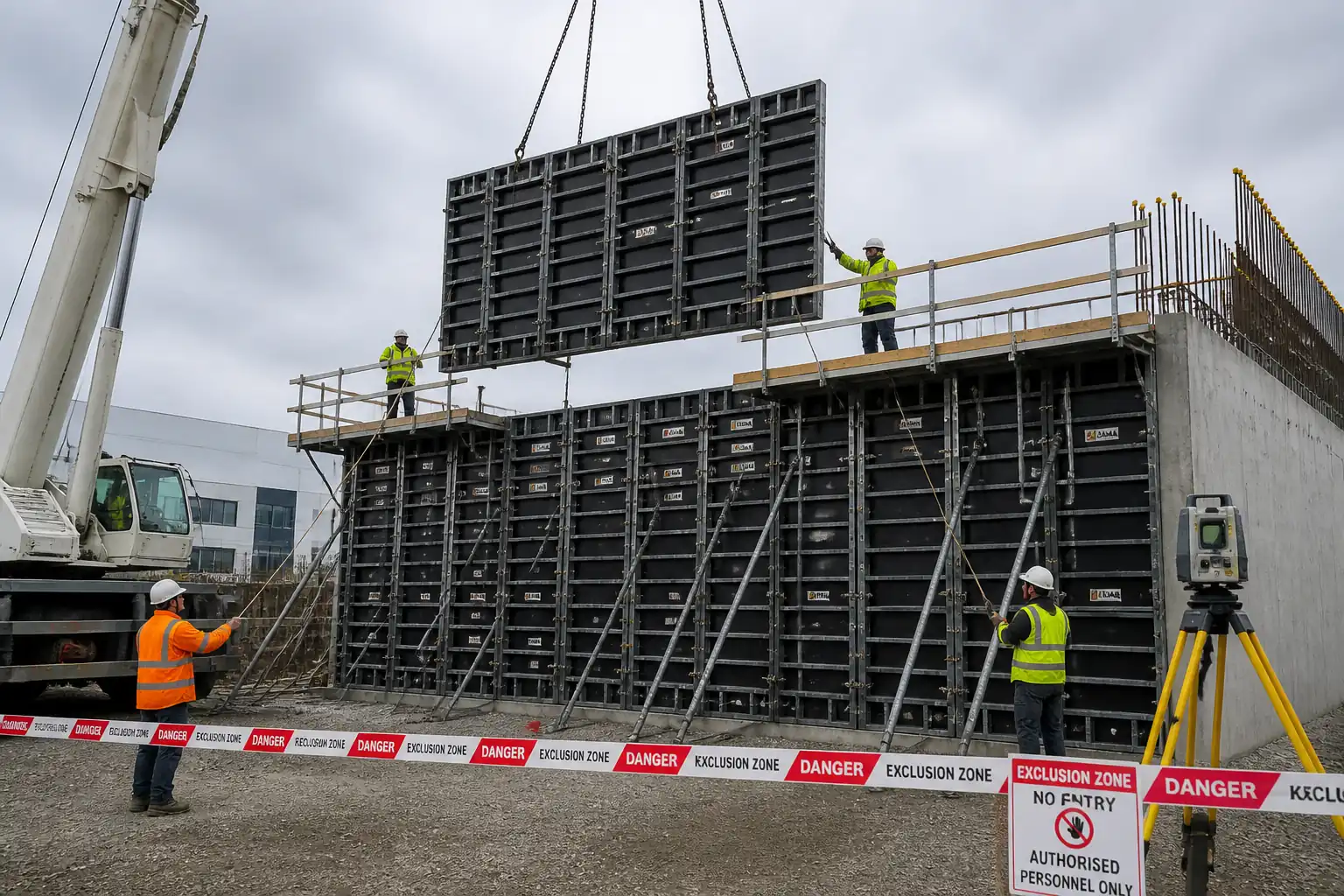
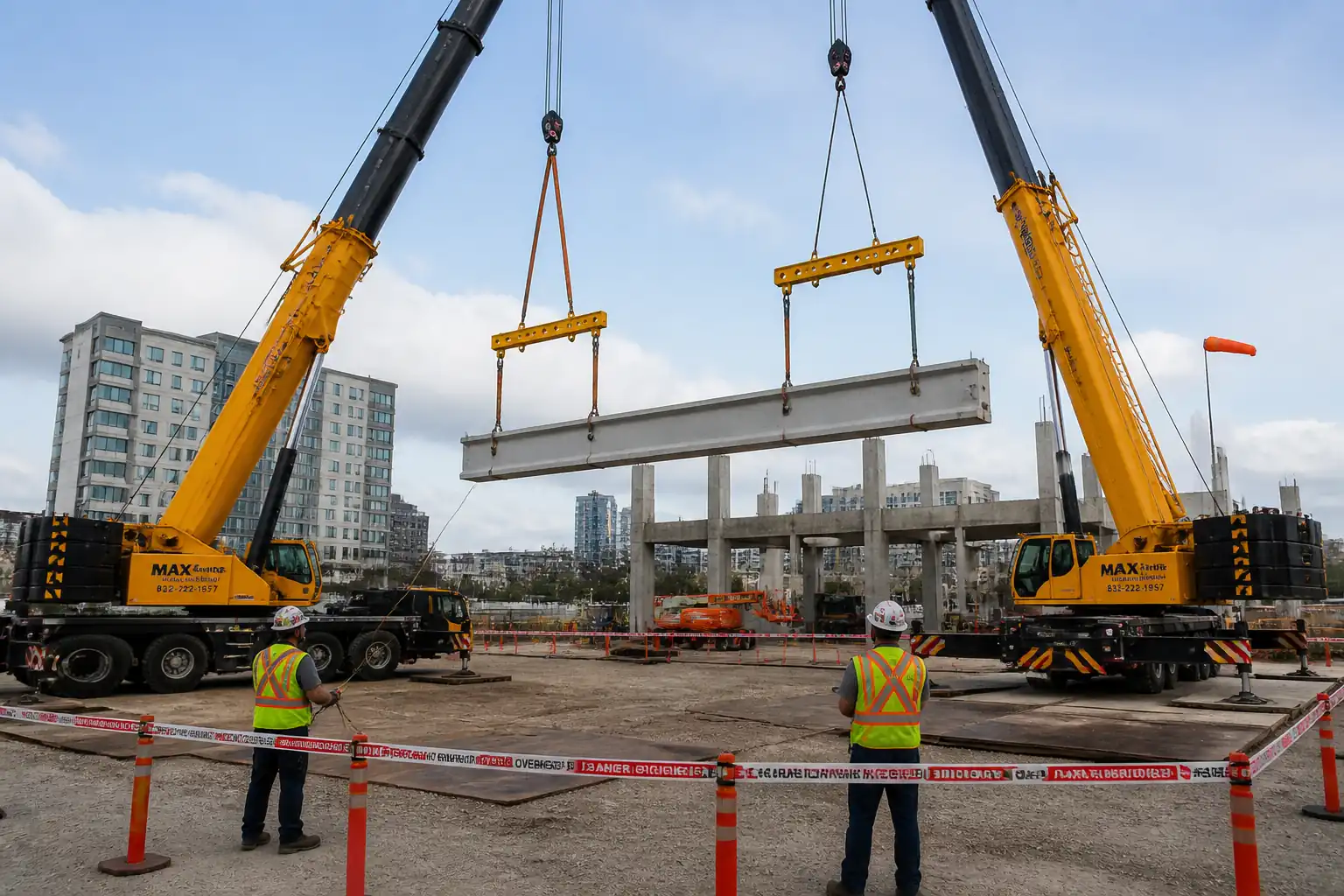
This method statement covers the end-to-end site activities for precast concrete wall panel installation including: incoming delivery inspections; storage and handling; crane lifting operations; rigging; setting, shimming, and line/level adjustments; temporary bracing; embedment and connection verification; welding/bolting as applicable; connection/base grouting; curing; QA/QC inspections and records; and final alignment acceptance checks.
Inclusions
- Pre-erection planning and lift plan development
- Inspection of panels upon delivery and prior to lift
- Crane setup, rigging selection, tag-line control
- Hoisting, positioning, plumbing, and temporary bracing of panels
- Verification of inserts, bearing, dowels/anchors, and connections
- Grouting of base and/or connections, and curing protection
- Survey and dimensional control for line, level, and plumbness
- Welding/bolting of permanent connections where specified
- Progressive and final inspections, records, and handover
Exclusions
- Fabrication of precast elements at factory
- Permanent architectural sealants unless stated in project specs
- Scaffolding beyond MEWP access for panel connections
- Structural design of panels, lifting inserts, or bracing systems (by Designer)
Key Acceptance Targets [Verify per project specifications]
- Plumbness: ≤ 6 mm in 3 m, and ≤ 12 mm overall panel height
- Horizontal/vertical position: ±10 mm
- Joint width: nominal per drawings, tolerance ±6 mm
- Bearing length at supports: typically ≥ 50 mm
- Base grout compressive strength: as specified (typ. ≥ 45 MPa at 28 days)
- Bolted connection torque: per manufacturer/drawings
- Weld profile/size: per drawings; visual acceptance to applicable welding code
- Surface damage/repairs: within approved repair criteria
Constraints
- Lifts shall not proceed in sustained wind above 9–12 m/s (project limit to be confirmed) [Verify per project HSE plan and specifications].
- Temporary bracing shall remain until all permanent connections are completed and grout/anchorage strengths achieved and verified by Engineer.
References
| Document Type | Reference / Number | Revision | Notes |
|---|---|---|---|
| Standard | PCI Erectors Manual; PCI Design Handbook | ||
| Standard | ACI 318; ACI 117; BS EN 13670 | ||
| Standard | ASTM C1107; ASTM C109; EN 1504-6 | ||
| Standard | AWS D1.1; EN 1090; ISO 17637; ISO 23278 | ||
| Standard | ASME B30.5; ASME B30.26; EN 13155; EN 13414 | ||
| Standard | ISO 9001; ISO 45001; ISO 14001 |
Responsibilities
| Role | Responsibility | Name / Party |
|---|---|---|
| PM | Project Manager | Contractor |
| AP | Appointed Person | Contractor |
| Supervisor | Crane Supervisor | Contractor |
| QA/QC | QA/QC Engineer | Contractor |
| Engineer/Surveyor | Site Engineer | Contractor |
| HSE | HSE Officer | Contractor |
| WI | Welding Inspector | Third-Party/Contractor |
| Crew | Riggers/Erectors | Contractor |
Resources
| Resource Type | Description | Quantity | Remarks |
|---|---|---|---|
| Manpower | Crane operator (certified) | 1 | |
| Manpower | Crane supervisor + appointed person | 2 | |
| Manpower | Riggers/slingers | 2-4 | |
| Manpower | Erectors/fitters | 2-4 | |
| Manpower | Site engineer/surveyor | 1 | |
| Manpower | QA/QC engineer | 1 | |
| Manpower | HSE officer | 1 |
Materials
| Material | Specification / Grade | Quantity | Remarks |
|---|---|---|---|
| Precast concrete | Per approved drawings and specs | As per BOQ | |
| Cementitious grout | ASTM C1107 | As required | |
| HDPE/SS/Neoprene | Per drawings | As required | |
| Steel | Per drawings/manufacturer | As required | |
| Welding electrodes/wire | AWS/EN class per WPS | As required | |
| Steel | Per supplier design | As required |
Equipment
| Equipment | Capacity / Type | Quantity | Inspection Required |
|---|---|---|---|
| Hydraulic crane | Per lift plan | 1 | Yes |
| Slings/clutches/shackles | Per plan | Set | Yes |
| MEWP | As required | Yes | |
| Survey kit | 1 set | Yes | |
| Mixer/pump | As required | Yes | |
| Mats/barriers/radios | As required | Yes |
Prerequisites
- Approved shop drawings, erection drawings, and connection details issued IFC.
- Approved method statement and ITP; approved lift plan with rigging calculations.
- Ground bearing capacity verified against outrigger loads; mats sized accordingly. Surveyed crane set-up pad with level tolerances per crane manufacturer.
- Utilities scan/permit-to-dig for outrigger locations; powerline exclusion verified [Verify per project HSE plan and local regulations].
- Panel delivery schedule and storage plan approved; panel ID matrix issued.
- Competency certificates for crane operator, riggers/slingers, welders, MEWP operators.
- Calibrations in date for torque wrench and survey instruments.
- Product approvals/COCs: non-shrink grout, bolts/anchors, braces.
- Weather monitoring equipment (anemometer) operational; project wind limits briefed.
- Pre-start coordination meeting and task-specific toolbox talk completed; rescue plan for MEWP work-at-height in place.
- Inspection and test forms printed/available: delivery inspection, pre-lift checklist, bracing log, torque/weld logs, grout batch log, survey report.
Method Sequence
| Step | Activity | Description | Responsibility | Inspection / Hold Point |
|---|---|---|---|---|
| 1 | Delivery receipt and staging | Receive panels, verify ID vs. schedule, check for transport damage, lifting anchors, embedded plates, and connection hardware. Stage on firm level dunnage with bearing along designed edges; avoid point loading. | Site Engineer / QA-QC / Riggers | Incoming inspection |
| 2 | Pre-lift checks | Conduct pre-lift briefing. Inspect crane certificates and daily checklist; verify rigging gear color-code and SWL; confirm lift weights and radii vs. lift plan; check wind speed. | Crane Supervisor / AP | Pre-lift checklist |
| 3 | Rigging the panel | Attach manufacturer-approved lifting clutches to cast-in anchors; use spreader if required to control sling angles (target ≥ 60° included angle). Fit tag lines at panel edges. | Riggers | Rigging inspection |
| 4 | Trial lift and hoist | Lift panel 100–200 mm to check balance and insert engagement; hold and recheck. Hoist clear, slew and travel within exclusion zone only. Maintain tag-line control; stop if gusts exceed limit. | Crane Operator / Riggers | Operator/rigger observation |
| 5 | Setting on shims/bearing pads | Lower panel onto pre-placed shims/pads. Achieve nominal bearing (typ. ≥ 50 mm) and initial line/level. Use pry bars only at planned lift points; protect edges. | Erectors / Site Engineer | Witness by QA/QC |
| 6 | Temporary bracing install | Install adjustable braces to panel and slab/foundation anchors as per brace layout. Tighten to hold plumb. Verify anchor edge distances and embedment per supplier design. | Erectors | Brace inspection |
| 7 | Plumbing and alignment | Using total station/laser, adjust braces and shims for plumbness and line. Check joint gaps against drawings. Record measurements. | Site Engineer / Surveyor | Survey check |
| 8 | Connection works: bolting/welding | Install and torque bolts or perform welding per drawings/WPS. Protect adjacent concrete from heat. Maintain brace support during operations. | Erectors / Welder / WI | Torque verification; weld VT and NDT (if required) |
| 9 | Grouting of base and connections | Prepare surfaces, pre-soak if required, mix grout per manufacturer, place by gravity or pump from one side to avoid voids. Maintain head pressure; cure and protect from vibration and traffic. | Erectors / QA-QC | Witness grout placement |
| 10 | Finish, protection, and sealant interface | Clean exposed faces, protect with pads where risk of impact. Install temporary weather protection to open joints pending sealant works (by others unless included). | Erectors | Visual |
| 11 | Release criteria and brace removal | After all permanent connections complete and grout/anchorage strengths verified, confirm final survey within tolerance; obtain Engineer approval; then remove braces in controlled sequence. | Site Engineer / QA-QC | Hold point before brace removal |
| 12 | Final acceptance inspection | Joint, surface, plumbness, and connection verification with Client/Engineer; close-out documentation submitted. | PM / QA-QC / Client Rep | Final acceptance |
Health, Safety, and Environment: Safety Controls
Key Hazards and Controls
- Hazard: Crane overturning due to inadequate ground capacity
- Likely consequence: Catastrophic injury/fatality, property damage
- Engineering/procedural control: AP to calculate outrigger reactions; verify soil bearing; install engineered mats/plates; keep outriggers fully extended/leveled; daily crane level check
- Required PPE: Hard hat, hi-vis, safety boots, gloves
- Collective prevention: Exclusion zone with barriers and banksman control; use anemometer and wind alarms
-
Inspection/permit/supervision: Lift plan approval; daily crane checklist; HSE inspection; [Verify per project HSE plan and local regulations]
-
Hazard: Load drop/rigging failure
- Consequence: Serious injury/fatality, panel damage
- Control: Use certified clutches/slings with SWL ≥ 1.5× leg load; pre-use inspection; maintain minimum sling angle per plan; trial lift 100–200 mm; no personnel under load; tag lines for control
- PPE: Hard hat with chin strap, gloves, safety boots, eye protection
- Collective: Exclusion zone sized to boom radius + 10% buffer; radio comms protocol
-
Inspection/permit/supervision: Rigging register; color coding; competent rigger supervision
-
Hazard: Wind-induced panel sail effect
- Consequence: Uncontrolled swing, brace overload, collapse
- Control: Stop lifts if sustained wind > project limit (typ. 9–12 m/s) or gusts exceed limit; use tag lines; store panels flat if high winds forecast
- PPE: As above plus wind-rated eye protection if dust present
- Collective: Weather monitoring and work-stop authority
-
Inspection/permit/supervision: Record wind readings on lift log
-
Hazard: Working at height from MEWP
- Consequence: Falls from height, entrapment
- Control: Trained operator; full body harness with short lanyard to MEWP anchor; maintain clearances; implement entrapment protection
- PPE: Harness with lanyard, helmet with chin strap
- Collective: MEWP rescue plan and dedicated spotter
-
Inspection/permit/supervision: MEWP inspection tag; pre-use functional test; permit to work at height
-
Hazard: Temporary bracing/anchor failure
- Consequence: Panel instability/fall
- Control: Bracing design by competent supplier; anchors installed to required embedment and torque; double-nut locking; daily brace inspection
- PPE: Gloves, eye protection, boots
- Collective: Do not remove braces until written release by Engineer
-
Inspection/permit/supervision: Brace log; daily inspection checklist
-
Hazard: Welding fumes, heat, and fire (if applicable)
- Consequence: Burns, eye injury, fire
- Control: Hot work permit; fire blankets; fire watch; correct WPS parameters; fume control/ventilation
- PPE: Welding shield, FR clothing, gloves
- Collective: Fire extinguishers 9 L foam/CO2; designated hot-work zone
-
Inspection/permit/supervision: Hot work permit; post-weld fire watch 30 min minimum [Verify]
-
Hazard: Pinch/crush between panel and structure
- Consequence: Hand injuries, fractures
- Control: Use push/pull poles; never place hands on pinch lines; brief exclusion zones for erectors
- PPE: Cut-resistant gloves, boots
- Collective: Banksman to coordinate approach and landing
-
Inspection/permit/supervision: Supervisor oversight during landing
-
Hazard: Electrical contact with overhead lines
- Consequence: Electrocution
- Control: Survey and maintain statutory clearances; spotter dedicated to line clearance; de-energize if within restricted zone [Verify]
- PPE: Dielectric gloves if required; standard PPE
- Collective: Physical barriers and signage
-
Inspection/permit/supervision: Permit-to-work near HV lines
-
Hazard: Manual handling of shims/gear
- Consequence: Musculoskeletal injury
- Control: Use mechanical aids; team lifts; weight limits enforced
- PPE: Gloves, boots
- Collective: Task rotation
-
Inspection/permit/supervision: Supervisor to monitor lifting technique
-
Hazard: Noise and vibration from plant
- Consequence: Hearing damage
- Control: Maintain equipment; limit exposure; schedule noisy works
- PPE: Hearing protection (SNR ≥ 25 dB)
- Collective: Noise barriers where feasible
-
Inspection/permit/supervision: Spot measurements if required
-
Hazard: Silica dust from drilling (brace anchors)
- Consequence: Respiratory irritation/silicosis (chronic)
- Control: Use wet drilling or M-class vacuum extraction; minimize dry sweeping
- PPE: FFP3/N95 respirator when dust potential exists
- Collective: Local extraction units
- Inspection/permit/supervision: Permit and equipment inspection
Note: Where exact controls depend on local law or project HSE plan, apply requirements and permits accordingly [Verify per project HSE plan and local regulations].
Environmental Controls
- Grout washout and cementitious waste: Mix/clean in contained area; capture wash water; dispose per approved method; prevent discharge to drains.
- Noise: Limit working hours; use well-maintained equipment; deploy temporary sound barriers if working near receptors.
- Dust from drilling/cutting: Use wet methods or local extraction; cover stockpiles; no dry sweeping; wheel wash if needed.
- Fuel and hydraulic leaks: Drip trays under crane and pumps; spill kits at point of use; immediate spill response; report and record spills.
- Waste segregation: Separate steel packaging, pallets, plastic wraps; send to approved recyclers; maintain waste transfer notes.
- Traffic and logistics: Stagger deliveries; designated routes; engines off when idle > 3 minutes; banksman for reversing.
- Wildlife and stormwater: Keep runoff paths clear; silt socks around drains near working area; no storage within buffer of watercourses [Verify].
- Carbon and energy: Avoid re-lifts by accurate planning; use electric MEWPs where feasible; minimize generator idling.
Quality Assurance and Quality Control
Documentation and Controls
- Pre-works: Verify approvals for shop drawings, erection drawings, lift plan, method, and ITP. Confirm latest revisions on site.
- Materials: Check COCs for grout, bolts/anchors, braces; verify panel IDs vs. schedule; ensure storage prevents damage.
- Calibration: Survey instruments and torque wrenches within calibration.
Inspection and Testing
- Delivery inspection: 100% of panels; record defects with photos and assign disposition (accept/repair/reject) per repair criteria.
- Survey checks: Each panel after plumbing and before release; record plumbness, joint width, position, bearing.
- Bolted connections: 100% visual; torque verification sampling: 10% minimum or all critical connections [Verify].
- Welding (if applicable): 100% VT; NDT extent per spec (typ. 10–25% MT/UT on critical welds) [Verify]. WPS and welder qualifications verified.
- Grout: One set of compressive strength specimens per shift or per lot (e.g., per 25–50 bags), whichever is more frequent [Verify]. Record ambient temperature, batch numbers, water dosage, flow.
- Bracing: Daily inspection of brace condition, anchors, and tightness until removal.
Hold/Witness Points [Verify per ITP]
- Prior to lifting first panel (H)
- After initial setting/shimming and bracing (W)
- Prior to welding/bolting (W/H if critical)
- During grout placement (W)
- Before brace removal (H)
- Final acceptance survey (W)
Records
- Lift plan approval, toolbox talks, delivery and damage reports, pre-lift checklists, rigging logs, survey reports, torque/weld logs, grout logs and test results, brace inspection logs, NCRs/Corrective actions, as-builts, completion certificate.
Attachments
- Approved erection drawings and connection details
- Lift plan with crane selection, rigging calculations, exclusion zone drawings
- Ground bearing pressure calculation and outrigger mat sizing
- Certificates: crane, rigging gear, MEWP, braces; operator/riggers/welders qualifications
- Product data and COCs: non-shrink grout, bolts/anchors, setting pads, braces
- WPS/WPQR and weld maps (if applicable)
- Daily pre-lift and rigging checklists; brace inspection log
- Survey control and as-built reports
- Grout batch records and compressive strength test results
- Torque logs; NDT reports; NCRs and close-out records
- HSE permits (hot work, working at height, near powerlines), risk assessments (RAMS), toolbox talks
- Manufacturer manuals for lifting inserts/clutches and braces
- Panel ID matrix and delivery schedule
This content is a read-only public reference. Download or customize to get an editable version.
ITP preview
The first inspection activities from the linked ITP for Method Statement: Precast Concrete Wall Panel Installation:
| Activity | Inspection / Test | Acceptance Criteria | Responsibility | Record |
|---|---|---|---|---|
| Pre-erection documentation | Verify approvals for drawings, method, ITP, lift plan, WPS (if any) | All approvals issued IFC and current revisions used | PM / QA-QC | Approved documents list / transmittals |
| Delivery inspection | Visual check of panels, IDs, embeds, lifting inserts | No unacceptable damage; IDs match schedule; embeds present and sound | QA-QC / Site Engineer | Delivery/inspection report with photos |
| Crane and rigging pre-use | Check certificates, daily checklists, SWL tags, color coding | Valid certs; gear defect-free; capacity adequate at radius | Crane Supervisor / AP | Pre-use checklists; rigging register |
Showing 3 of 12 inspection activities. View full ITP →
Related Inspection and Test Plan
An Inspection and Test Plan (ITP) is available for Method Statement: Precast Concrete Wall Panel Installation. The ITP defines the inspection activities, acceptance criteria, hold and witness points, responsible parties, and records required to verify the work described in this method statement.
View the Method Statement: Precast Concrete Wall Panel Installation ITP →Frequently asked questions
Continue with related Quollnet resources connected to this method statement.