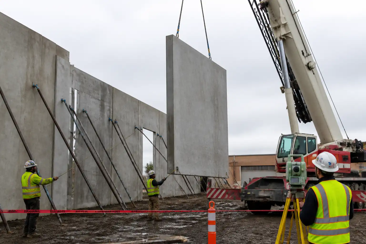
Method Statement: Erection of Precast Beams on Corbels/Column Heads with Bearing Pads, Temporary Stability, and Grouting – Method Statement
AI-assisted method statement with matching ITP, PDF download, and Excel export.
More than a static template
Unlike a downloadable Word or PDF template, this method statement is an AI-assisted editable starting point connected directly to a matching Inspection and Test Plan. Every section is structured, project-adaptable, and ready to export.
- AI-assisted drafting — Customize every section with AI for your specific project scope.
- Linked ITP — A matching inspection and test plan is generated alongside the method statement.
- Multiple export formats — Download as a formatted PDF or editable Excel spreadsheet.
- Editable starting point, not a final document — Review, verify, and adjust all content against your project requirements before use.
Static template vs. Quollnet workflow
| Feature | Static template | Quollnet |
|---|---|---|
| Project-specific content | Manual fill-in required | AI-assisted customization |
| Linked ITP | Separate document, no link | Matching ITP included |
| Export formats | Usually PDF only | PDF and Excel |
| Structured sections | Free-form layout | 13 standardized sections |
| Saved to your account | Local file only | Cloud-saved, reusable |
| Content accuracy | You verify everything | AI-assisted, you still verify |
| Cost | Often free but time-intensive | Free to customize and download |
What you can customize
When you save this method statement to your account, every section becomes editable. The following 13 sections are included:
- Scope — Defines the activity and its boundaries.
- References — Standards, specifications, and drawings.
- Responsibilities — Roles and accountabilities.
- Resources — Labour, plant, and equipment summary.
- Materials — Materials and compliance requirements.
- Equipment — Tools and equipment details.
- Prerequisites — Hold points and pre-conditions.
- Method sequence — Step-by-step construction sequence.
- Safety controls — HSE risk controls and PPE.
- Environmental controls — Environmental mitigation measures.
- QA/QC — Quality inspection and test requirements.
- ITP — Inspection and Test Plan table (has its own page).
- Attachments — Referenced drawings and documentation.
Why this method statement is used
This method statement is used to define and communicate the approved procedure for carrying out method statement: erection of precast beams on corbels/column heads with bearing pads, temporary stability, and grouting on site. It ensures the work is planned in advance, the correct resources and controls are in place, and all personnel understand responsibilities, sequence, quality requirements, and safety controls before work begins. It aligns site execution with the documented scope and acceptance expectations.
Who uses this method statement
This method statement is used by contractors, site supervisors, project engineers, QA/QC engineers, HSE officers, consultants, and client representatives. It serves as a shared reference for planning, execution, supervision, inspection, and approval of the activity on site.
When it is prepared and submitted
The method statement is prepared before the work activity starts and submitted as part of the pre-construction documentation package for review and approval.
Who reviews or approves it
The method statement is usually submitted to the client representative, consultant, resident engineer, or project management consultant for review and approval before the work commences.
Important approval note
This method statement is an AI-assisted editable starting point, not a pre-approved document. Before use on any project, all content must be reviewed and approved by the relevant parties (superintendent, principal contractor, or client representative) in accordance with your contract and project quality plan.
For example: if your specification requires a departure from a referenced standard, that departure must be documented and approved separately — this method statement will not capture that automatically. Always verify against your applicable drawings, specifications, and regulatory requirements.
Method statement content
Scope
Overview
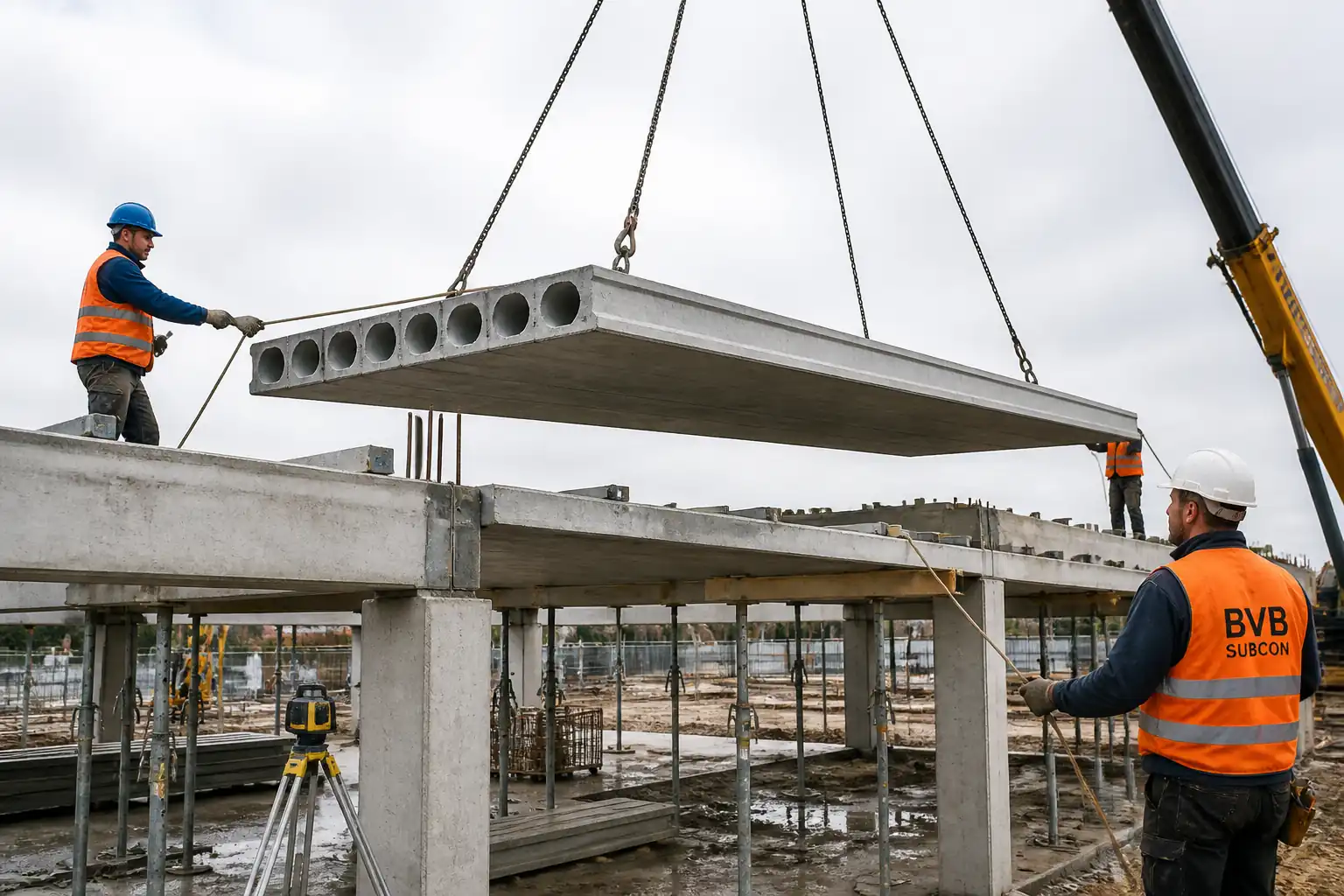
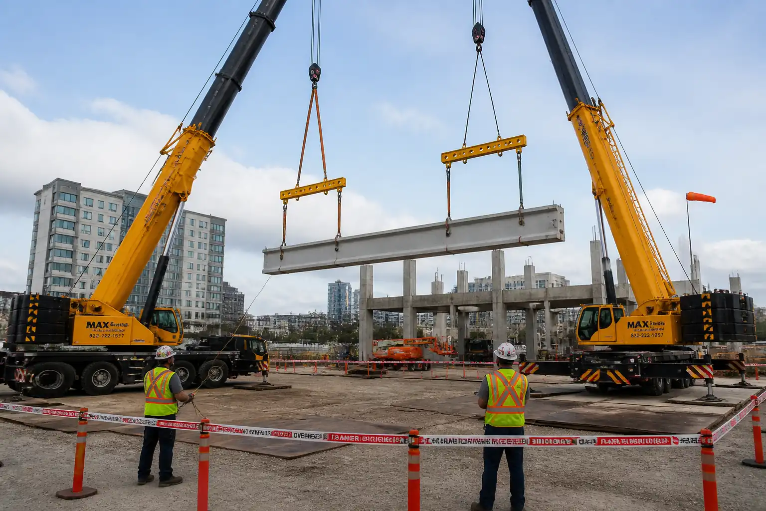
This method statement covers supply verification, placement, and fixation of elastomeric bearing pads; erection of precast concrete beams onto corbels or column heads; verification of seating length and alignment; provision of temporary stability/bracing until permanent connections are completed; installation of specified connections; and grouting of bearing gaps/pockets. Includes inspections, tolerances, hold/witness points, and testing.
Inclusions
- Pre-erection surveys of supports (corbels/column heads) for geometry, level, and concrete strength.
- Bearing pad preparation, placement, and positioning.
- Lifting, aligning, and setting precast beams onto supports.
- Verification of seating length and pad contact.
- Temporary stability via designed props/bracing until continuity achieved.
- Installation of specified mechanical/welded/grouted connections (as detailed on IFC/shop drawings).
- Grouting of bearing interfaces/pockets and curing.
- Final survey, as-built records, release of temporary works, and demobilization.
Exclusions
- Fabrication of precast members (covered by supplier QC).
- Permanent composite topping or slab installation beyond immediate stability requirements.
- Electrical/mechanical works not directly related to beam stability.
Key Benchmarks [Verify per project specifications]
- Minimum design seating length: typically 75–100 mm for beams on corbels; use design value.
- Position tolerance of bearing pad: ±5 mm from design centerline; full pad within support.
- Beam line/level after set: line ±10 mm; level at bearing ±5 mm; cross-fall ≤1:200.
- Do not load beam (other than self-weight) until grout reaches specified strength (e.g., ≥30 MPa or ≥70% of fck).
References
| Document Type | Reference / Number | Revision | Notes |
|---|---|---|---|
| Standard | BS EN 13369 | ||
| Standard | BS EN 13670 / ACI 117 | Use project-governing code base. | |
| Standard | BS EN 1992-1-1 (EC2) / ACI 318 | ||
| Standard | BS EN 1337 series / ASTM D4014 | ||
| Standard | ASTM C1107 / EN 1504-3 (R3/R4) | Flow, strength, volume stability; [Verify grade]. | |
| Standard | BS 7121 series / ASME B30.20 | Plus [Verify per project HSE plan and local regulations]. | |
| Standard | BS 5975 | Temporary works procedures and checks. | |
| Standard | ISO 17123 series | Calibration and field procedures. |
Responsibilities
| Role | Responsibility | Name / Party |
|---|---|---|
| Project Manager | Ensure compliance with contract and standards. | Main Contractor |
| TWC | Issue TWC permit to load/release. | Main Contractor |
| Lifting Supervisor | Issue Lift Plan and conduct pre-lift briefing (TBT). | Main Contractor |
| Site Engineer | Maintain ITP, RFI, and as-built records. | Main Contractor |
| QA/QC | Compile MDR and handover docs. | Main Contractor |
| HSE | HSE supervision and audits. | Main Contractor |
| Surveyor | Instrument calibration verification. | Main Contractor |
| Operator/Rigger | Safe lifting practices. | Main Contractor/Subcontractor |
| Supplier Rep | Provide product data and tolerances. | Precast Supplier |
Resources
| Resource Type | Description | Quantity | Remarks |
|---|---|---|---|
| Personnel | Foreman, riggers (2–4), signaler, general operatives (2–4). | 1 crew | Adjust to lift complexity. |
| Personnel | Surveyor + assistant. | 1 team | |
| Personnel | 1 QA/QC engineer, 1 HSE officer shared. | As required |
Materials
| Material | Specification / Grade | Quantity | Remarks |
|---|---|---|---|
| Elastomer | To design | As per drawings | |
| Grout | C1107/EN1504 | As required | |
| Steel | BS EN 10025 | As required | |
| Steel | Per design | As per TW design | |
| Steel | ISO 898-1 / ETA | As required | |
| Foam/plywood/sealant | As required |
Equipment
| Equipment | Capacity / Type | Quantity | Inspection Required |
|---|---|---|---|
| Crane | [Per lift plan] | 1 | Yes |
| Set | Yes | ||
| As required | Yes | ||
| 1 set | Yes | ||
| 1 set | Yes | ||
| Set | Yes |
Prerequisites
- IFC drawings, precast shop drawings, bearing details, and temporary works design approved by the Engineer.
- Lift plan approved by Appointed Person; crane mats and ground bearing capacity verified [Verify per geotechnical report].
- PTWs issued: Lifting permit, Working at Height permit, Hot Work (if welding), and Grouting/Chemical permit as applicable [Verify per project HSE plan and local regulations].
- Supports (columns/corbels) concrete strength achieved: ≥ design value for bearing and anchor installation (e.g., ≥30 MPa) [Verify per mix reports].
- Survey control established and referenced to project grid; benchmarks available and protected.
- Bearing surfaces prepared: laitance removed, level checked, dry and clean; any defects repaired and signed-off.
- Utilities and overhead obstructions checked/cleared; exclusion zones set; wind forecast checked (suspend lifts if sustained wind >10–12 m/s or per crane manufacturer, whichever is lower) [Verify].
- Materials approved, identified by batch; test certificates available (bearing pads, grout, anchors).
- Emergency response plan briefed; first aid and spill kits on site.
- Toolbox Talk conducted for entire crew covering task-specific hazards and controls.
Method Sequence
| Step | Activity | Description | Responsibility | Inspection / Hold Point |
|---|---|---|---|---|
| 1 | Pre-erection survey of supports | Verify corbel/column head dimensions, levels, and coordinates; check reinforcement exposure and bearing seat flatness; check concrete strength records. | Site Engineer/Surveyor | ITP Hold Point H1 |
| 2 | Bearing pad preparation and placement | Measure and mark bearing pad centerlines; cut pads if permitted by supplier; solvent-clean surfaces; place pads to design thickness; tack with approved adhesive if required; ensure full support within corbel footprint. | Site Engineer/Foreman | Witness |
| 3 | Pre-lift checks and rigging | Inspect beam for damage; verify lifting points; fit appropriate clutches/slings; attach tag lines; confirm crane radius and outrigger setup per lift plan; brief team. | Lifting Supervisor | Pre-lift inspection |
| 4 | Trial lift and slew to position | Hoist clear; verify stability; slew to column line under tag line control; maintain minimum clearances from structures and power lines. | Crane Operator/Riggers | Supervision |
| 5 | Set beam onto pads and align | Lower slowly; align to marks; ensure no fouling of inserts/rebars; gently land on pads; check immediate stability while crane maintains slight tension. | Lifting Supervisor/Site Engineer | ITP Witness Point W1 |
| 6 | Verify seating length and line/level | Measure effective seating length along both beam ends; check beam line/level and cross-fall; adjust with approved shims if permitted by design. | Site Engineer/Surveyor | ITP Hold Point H2 (before crane release) |
| 7 | Install temporary stability/bracing | Install props/braces to TW design; connect to cast-in sockets/anchors; apply specified pre-load/torque; check plumb; crane remains attached until bracing complete and signed-off. | TWC/Foreman | ITP Witness Point W2 |
| 8 | Release crane and proceed to next beam | Once H2/Hold released and bracing complete, release crane and repeat sequence. | Lifting Supervisor | Sign-off |
| 9 | Install permanent connections | Fit/weld/bolt/grout connections per drawings (e.g., steel angles, dowel grouting, shear keys). Protect pads from heat if welding; maintain alignment. | Site Engineer/Foreman | ITP Witness Point W3 (as applicable) |
| 10 | Prepare for grout | Install grout stops/formers; clean and pre-wet surfaces to SSD; confirm vent/prime if required by grout manufacturer; temperature within range. | Site Engineer/QA/QC | Pre-pour check |
| 11 | Mix and place grout | Mix per manufacturer; record water content; achieve target flow; place from one side to avoid entrapped air until full bearing; do not disturb pads; cure as specified; protect from vibration. | Foreman/QA/QC | ITP Witness Point W4 |
| 12 | Curing and protection | Maintain curing regime (wet cure or curing compound compatible with grout); prevent load or impact until required strength achieved. | Foreman/QA/QC | Routine |
| 13 | Final survey and de-propping | Survey final line/level; check connections; upon Engineer/TWC approval and grout strength, progressively remove temporary works. | TWC/Site Engineer | ITP Hold Point H3 (before de-prop) |
| 14 | Handover documentation | Compile MDR: ITP, inspections, materials, tests, as-builts, permits, NCR close-outs. | QA/QC Engineer | Review |
Health, Safety and Environment (HSE) – Safety Controls
Task-specific hazards and controls
1) Hazard: Suspended loads during crane lifts
- Likely consequence: Crushing, fatality
- Engineering/procedural control: Approved lift plan; defined exclusion zone (radius per load path + 10% buffer); tag lines; no standing under load; weather limits per crane OEM; pre-lift briefing and standard hand signals/radios.
- Required PPE: Helmet with chin strap, high-vis, safety boots, gloves, eye protection.
- Collective preventive measure: Physical barriers and banksman at access points.
- Inspection/permit/supervision: Daily crane/rigging inspections; current certifications; Lifting Permit; Lifting Supervisor present.
2) Hazard: Working at height on columns/beam levels
- Likely consequence: Falls, serious injury
- Engineering/procedural control: Use MEWP or full-edge protected platforms; 100% fall arrest in MEWP; maintain three points of contact; restrict climbing on precast; fit temporary edge protection where feasible.
- Required PPE: Full-body harness with lanyard (energy absorber), helmet with chin strap.
- Collective preventive measure: Guardrails on platforms; toe boards.
- Inspection/permit/supervision: Working at Height PTW; MEWP inspection log; competent operator.
3) Hazard: Pinch/crush points at bearings/corbels during set-down
- Likely consequence: Hand injuries, amputations
- Engineering/procedural control: Hands-off policy near bearing during lowering; use pry bars and alignment tools; keep crane load slightly live until seating verified.
- Required PPE: Impact-resistant gloves.
- Collective preventive measure: Exclusion line at bearing zone; dedicated spotter.
- Inspection/permit/supervision: Supervisor control during set-down; Toolbox Talk.
4) Hazard: Instability/toppling before bracing
- Likely consequence: Structural collapse
- Engineering/procedural control: Temporary works design; crane remains attached until braces installed; immediate installation of lateral restraints; verify anchor capacities and torque.
- Required PPE: Standard PPE.
- Collective preventive measure: Sequenced erection to ensure stability at each stage.
- Inspection/permit/supervision: TWC inspection and permit to proceed; ITP hold before crane release.
5) Hazard: Overhead/adjacent power lines or structures
- Likely consequence: Electrocution, collision
- Engineering/procedural control: Survey and mark exclusion distances; use goal-post barriers; spotter assigned; slew/height limiters if available.
- Required PPE: Standard PPE; dielectric gloves if required [Verify].
- Collective preventive measure: Physical barriers and signage.
- Inspection/permit/supervision: Permit/authorization from utility owner where required; daily brief.
6) Hazard: Welding/hot works for steel connections (if specified)
- Likely consequence: Burns, fire, eye damage, fume inhalation
- Engineering/procedural control: Hot Work Permit; fire watch; welding screens; protect elastomeric pads and concrete from heat (thermal blanket/heat sink); fume extraction where enclosed.
- Required PPE: Welding helmet, FR clothing, gauntlets, respirator as needed.
- Collective preventive measure: Fire extinguishers; fire blankets; remove combustibles.
- Inspection/permit/supervision: Hot Work PTW; welder qualifications; equipment inspection; gas leak checks.
7) Hazard: Cementitious grout handling
- Likely consequence: Skin/eye irritation, chemical burns
- Engineering/procedural control: Follow SDS; use mechanical mixing; avoid direct contact; eye-wash available.
- Required PPE: Chemical-resistant gloves, goggles/face shield, coveralls.
- Collective preventive measure: Controlled mixing area with bund; spill containment.
- Inspection/permit/supervision: SDS on site; HSE monitoring; permit for grouting if required.
8) Hazard: Noise and vibration from plant
- Likely consequence: Hearing loss, hand-arm vibration
- Engineering/procedural control: Maintain equipment; limit exposure durations; rotate tasks.
- Required PPE: Ear protection.
- Collective preventive measure: Schedule noisy works; signage of hearing protection zones.
- Inspection/permit/supervision: HSE checks; equipment maintenance records.
9) Hazard: Adverse weather (wind, lightning, rain)
- Likely consequence: Loss of control, slips, grout quality issues
- Engineering/procedural control: Suspend lifts above wind threshold; halt works during lightning; protect grout from rain and temperature extremes.
- Required PPE: Weather-appropriate PPE, anti-slip footwear.
- Collective preventive measure: Weather monitoring and stop-work authority.
- Inspection/permit/supervision: Supervisor to enforce weather criteria [Verify per project HSE plan and local regulations].
10) Hazard: Manual handling of pads/shims/formwork
- Likely consequence: Strains, injuries
- Engineering/procedural control: Use mechanical aids; team lifts; proper posture training.
- Required PPE: Gloves, boots.
- Collective preventive measure: Pre-stage materials to minimize carrying distances.
- Inspection/permit/supervision: HSE supervision and TBT.
Environmental Controls
- Cementitious runoff/grout washout:
- Control: Mix and washout in bunded area with impermeable liner; collect wastewater for proper disposal; no discharge to drains/watercourses.
- Monitoring: Supervisor to inspect containment; record volumes disposed.
- Noise and vibration:
- Control: Maintain equipment; restrict operations to permitted hours; use acoustic signals instead of horns where allowed.
- Monitoring: Periodic noise readings at site boundary [Verify per consent].
- Dust from cutting pads/shims or surface prep:
- Control: Prefer factory-cut pads; if cutting, use wet methods or local extraction; vacuum with HEPA filters.
- Monitoring: Visual checks; damp down as needed.
- Waste management:
- Control: Segregate elastomer offcuts, steel shims, packaging; recycle where possible; certified waste hauler.
- Monitoring: Waste transfer notes retained.
- Spills/fuels/hydraulics:
- Control: Drip trays under plant; spill kits at crane; immediate containment and cleanup.
- Monitoring: Daily plant checks for leaks.
- Wildlife and waterways protection:
- Control: Maintain buffer zones; silt socks if near drains.
- Monitoring: HSE inspections.
- Materials stewardship:
- Control: Store grout and pads off ground, covered, within manufacturer temperature limits.
- Monitoring: Storage inspections recorded weekly.
QA/QC Requirements and Tolerances
Quality Controls
- Material verification: COCs/COAs for bearing pads (hardness, dimensions), grout (compliance to ASTM C1107/EN 1504), anchors/bolts (grade/ETA).
- Equipment calibration: Survey instruments (≤12 months), torque wrenches (≤6 months), flow table/scoop as applicable.
- ITP implementation: Hold points before crane release, before grouting, and before de-propping.
- Testing: Grout flow per datasheet; compressive strength at 1/7/28 days (≥ specified) [Verify frequencies]; temperature logs.
- Records: Seating length sheets, survey as-builts, torque logs, grout batch sheets, cube reports, photographic evidence, NCR/CAR if deviations.
Tolerances [Verify per project specifications]
- Bearing pad location: ±5 mm from set-out; pad fully on support; no pad overhang.
- Seating length (each end): ≥ design minimum (typ. 75–100 mm); continuous contact along width; local gaps ≤2 mm if permitted by design.
- Beam line: ±10 mm relative to grid over span up to 20 m (adjust proportionally for longer spans).
- Beam level at bearings: ±5 mm; cross-fall ≤1:200.
- Plumb of beam web: ±10 mm at top over story height.
- Connection installation: Bolts to specified torque; weld quality per EN ISO 5817 [Verify level/class].
- Grouting: No voids; grout flush as detailed; shrinkage-compensated; curing compliant with datasheet.
Acceptance for Load Transfer
- Do not remove temporary supports or apply superimposed loads until:
- All permanent connections completed and inspected.
- Grout strength verified to meet or exceed specified threshold (e.g., ≥70% fck or ≥30 MPa) [Verify].
- TWC issues release permit.
Attachments
- Approved Lift Plan(s) and crane load charts
- Temporary Works Design and TWC permits
- IFC drawings and approved precast shop drawings (beam/corbel details)
- Bearing pad datasheets and certificates of compliance
- Grout product datasheets, MSDS, mixing/placement instructions
- Rigging certificates, operator licenses, MEWP certificates
- Calibration certificates (survey, torque wrench)
- Pre-erection survey reports and seating length records
- Grout test results (flow and compressive strength)
- As-built survey and handover/acceptance forms
This content is a read-only public reference. Download or customize to get an editable version.
ITP preview
The first inspection activities from the linked ITP for Method Statement: Erection of Precast Beams on Corbels/Column Heads with Bearing Pads, Temporary Stability, and Grouting:
| Activity | Inspection / Test | Acceptance Criteria | Responsibility | Record |
|---|---|---|---|---|
| Pre-erection survey of supports | Level/line survey; review concrete strength reports | Bearing seats within tolerance; concrete strength ≥ specified [Verify] | Site Engineer/QA-QC | Survey report; material test certificates |
| Bearing pad material verification | Certificates check; random dimension/hardness check if specified | Compliant with EN 1337/ASTM D4014; batch traceable | QA/QC | COC/COA; inspection checklist |
| Bearing pad installation | Dimensional check; position check | Location ±5 mm; full support; level difference ≤2 mm | Site Engineer | Pad installation sheet; photos |
Showing 3 of 13 inspection activities. View full ITP →
Related Inspection and Test Plan
An Inspection and Test Plan (ITP) is available for Method Statement: Erection of Precast Beams on Corbels/Column Heads with Bearing Pads, Temporary Stability, and Grouting. The ITP defines the inspection activities, acceptance criteria, hold and witness points, responsible parties, and records required to verify the work described in this method statement.
View the Method Statement: Erection of Precast Beams on Corbels/Column Heads with Bearing Pads, Temporary Stability, and Grouting ITP →Frequently asked questions
Continue with related Quollnet resources connected to this method statement.