Method Statement: Temporary Formwork and Falsework Support System for Reinforced Concrete Structural Elements – Method Statement
AI-assisted method statement with matching ITP, PDF download, and Excel export.
More than a static template
Unlike a downloadable Word or PDF template, this method statement is an AI-assisted editable starting point connected directly to a matching Inspection and Test Plan. Every section is structured, project-adaptable, and ready to export.
- AI-assisted drafting — Customize every section with AI for your specific project scope.
- Linked ITP — A matching inspection and test plan is generated alongside the method statement.
- Multiple export formats — Download as a formatted PDF or editable Excel spreadsheet.
- Editable starting point, not a final document — Review, verify, and adjust all content against your project requirements before use.
Static template vs. Quollnet workflow
| Feature | Static template | Quollnet |
|---|---|---|
| Project-specific content | Manual fill-in required | AI-assisted customization |
| Linked ITP | Separate document, no link | Matching ITP included |
| Export formats | Usually PDF only | PDF and Excel |
| Structured sections | Free-form layout | 13 standardized sections |
| Saved to your account | Local file only | Cloud-saved, reusable |
| Content accuracy | You verify everything | AI-assisted, you still verify |
| Cost | Often free but time-intensive | Free to customize and download |
What you can customize
When you save this method statement to your account, every section becomes editable. The following 13 sections are included:
- Scope — Defines the activity and its boundaries.
- References — Standards, specifications, and drawings.
- Responsibilities — Roles and accountabilities.
- Resources — Labour, plant, and equipment summary.
- Materials — Materials and compliance requirements.
- Equipment — Tools and equipment details.
- Prerequisites — Hold points and pre-conditions.
- Method sequence — Step-by-step construction sequence.
- Safety controls — HSE risk controls and PPE.
- Environmental controls — Environmental mitigation measures.
- QA/QC — Quality inspection and test requirements.
- ITP — Inspection and Test Plan table (has its own page).
- Attachments — Referenced drawings and documentation.
Why this method statement is used
This method statement is used to define and communicate the approved procedure for carrying out method statement: temporary formwork and falsework support system for reinforced concrete structural elements on site. It ensures the work is planned in advance, the correct resources and controls are in place, and all personnel understand responsibilities, sequence, quality requirements, and safety controls before work begins. It aligns site execution with the documented scope and acceptance expectations.
Who uses this method statement
This method statement is used by contractors, site supervisors, project engineers, QA/QC engineers, HSE officers, consultants, and client representatives. It serves as a shared reference for planning, execution, supervision, inspection, and approval of the activity on site.
When it is prepared and submitted
The method statement is prepared before the work activity starts and submitted as part of the pre-construction documentation package for review and approval.
Who reviews or approves it
The method statement is usually submitted to the client representative, consultant, resident engineer, or project management consultant for review and approval before the work commences.
Important approval note
This method statement is an AI-assisted editable starting point, not a pre-approved document. Before use on any project, all content must be reviewed and approved by the relevant parties (superintendent, principal contractor, or client representative) in accordance with your contract and project quality plan.
For example: if your specification requires a departure from a referenced standard, that departure must be documented and approved separately — this method statement will not capture that automatically. Always verify against your applicable drawings, specifications, and regulatory requirements.
Method statement content
Scope
Workscope
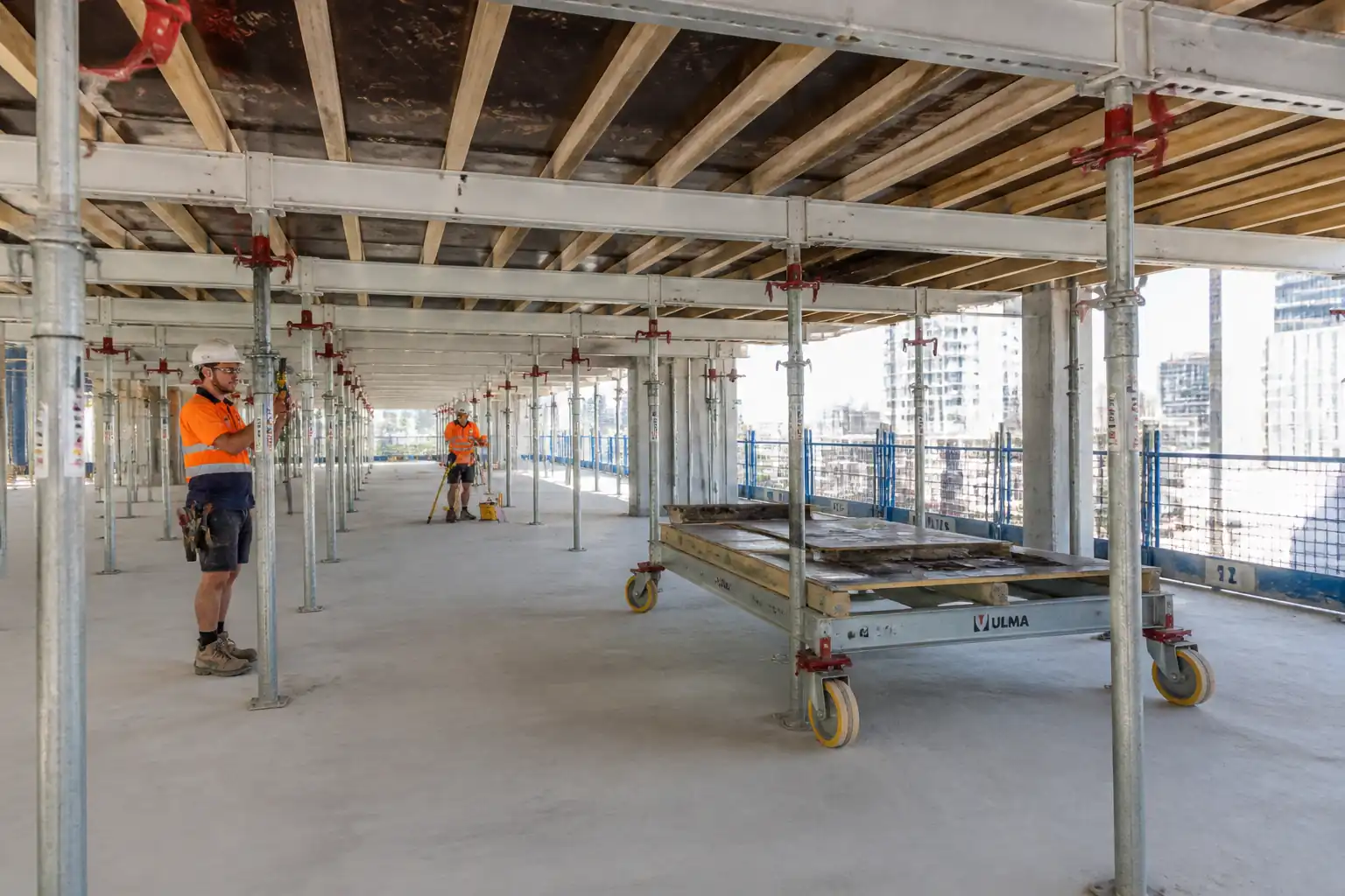
- Design, verification, supply, erection, inspection, loading, monitoring, striking, and removal of temporary formwork and falsework (including back-propping) for reinforced concrete slabs, beams, walls, and columns.
- Includes stability bracing, access platforms, fall protection, formwork facing, walers, shores/props, ties/anchors, soleplates, back-propping, and associated temporary works.
- Covers engineering checks for fresh concrete pressure, rate of pour, differential elevation/deflection, ground bearing for foundations of shores, wind effects on tall formwork, and load transfer during staging.
- Includes interface management with reinforcement, embedded items, MEP sleeves, concrete placement teams, and cranes/pumps.
- Exclusions: Permanent works design; concrete mix design; rebar fabrication/installation (coordination only); scaffolding not forming part of the support system (unless identified as falsework).
Objectives
- Provide a safe, stable, and serviceable temporary works system that controls deflection, alignment, and dimensional tolerances to meet permanent works geometry until concrete has attained strength sufficient for load transfer and striking.
- Establish inspection and test plan, hold/witness points, and documentation required prior to loading and removal.
References
| Document Type | Reference / Number | Revision | Notes |
|---|---|---|---|
| Standard | BS 5975 | ||
| Standard | EN 12812 | ||
| Standard | EN 13670 | ||
| Standard/Guide | ACI 347 / ACI 318 | ||
| Standard | EN 1991 | ||
| Standard | EN 1993 / EN 1995 / EN 338 | ||
| Standard | EN 1065 | ||
| Standards | ISO 9001 / ISO 45001 / ISO 14001 | ||
| Standards | BS EN 636 / BS EN 13986 |
Responsibilities
| Role | Responsibility | Name / Party |
|---|---|---|
| Engineer | Design | Specialist/Consultant |
| Management | Coordination | Main Contractor |
| Supervisor | Supervision | Main Contractor |
| Engineer | Survey | Main Contractor |
| Trades | Execution | Specialist/Subcontractor |
| QA/QC | Quality | Main Contractor |
| HSE | HSE | Main Contractor |
| Supervisor | Production | Concrete Subcontractor |
Resources
| Resource Type | Description | Quantity | Remarks |
|---|---|---|---|
| Personnel | Chartered engineer experienced in falsework/formwork design | 1 | |
| Personnel | Competent TWC per BS 5975 | 1 | |
| Personnel | Carpenters, erectors, riggers | 6–20 [Verify per workfront] | |
| Personnel | Total station/laser level operator | 1–2 | |
| Personnel | Certified crane operator and appointed person | As required |
Materials
| Material | Specification / Grade | Quantity | Remarks |
|---|---|---|---|
| Plywood panels | BS EN 636, BS EN 13986; thickness 18–21 mm; WBP/phenolic faced [Verify] | As per drawings | Film-faced plywood |
| Formwork beams | Capacity per manufacturer; service class per EN 1995; allowable deflection L/400 [Verify] | As per design | Timber H20 or aluminum beams |
| Steel props | EN 1065 class and capacity; jack extension within rated range [Verify] | As per design | Classes B/D/E as applicable |
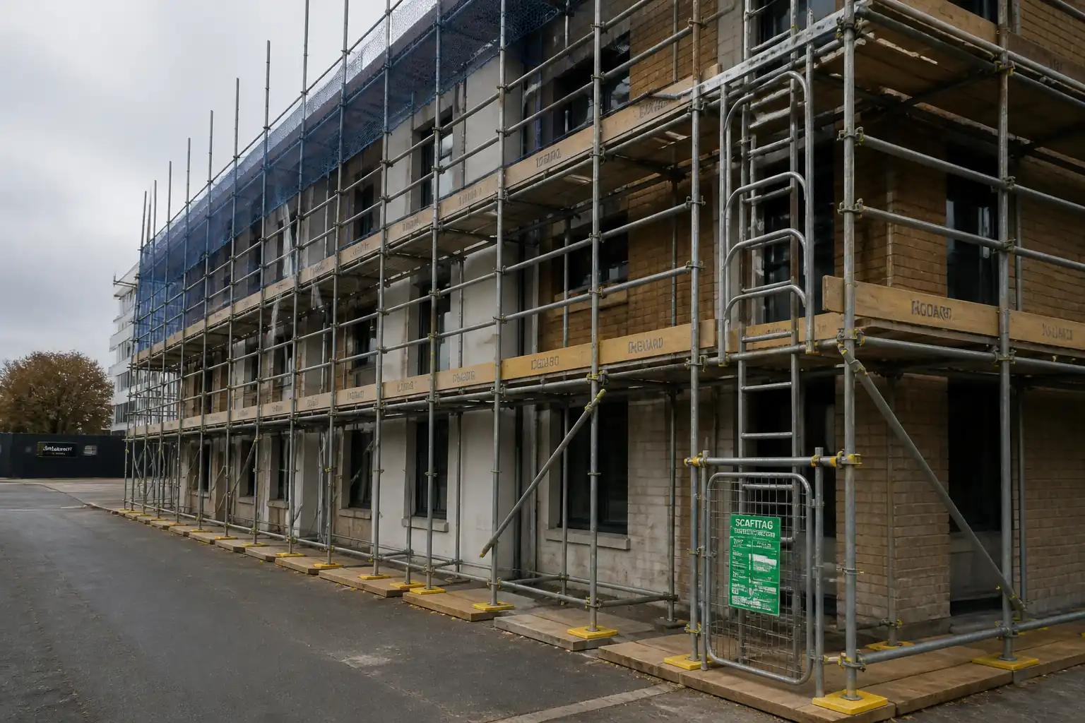
| Scaffold tubes/couplers/frames | EN 12811 components for access; capacities per EN 12812 design when used as falsework | As required | If tube-and-fitting used as falsework |
| Ties/anchors | Rated working load ≥ design load with SF per BS 5975 [Verify]; embedment per system manual | As per design | DW15/DW20 or proprietary |
| Soleplates | Timber C24 or steel plates sized to limit bearing pressure ≤ allowable [Verify] | As required | Timber or steel |
| Release oil | Manufacturer data; VOC compliant [Verify] | As required | Non-staining, compatible |
| Props/tubes/beams | Capacity per design; positions per TWD drawings | As per design | To control load redistribution |
Equipment
| Equipment | Capacity / Type | Quantity | Inspection Required |
|---|---|---|---|
| Crane/telehandler | Capacity > heaviest lift with ≥10% margin [Verify] | As required | Daily checks; certification in date |
| MEWP/scaffold | Safe working platforms rated ≥ 2.0 kN/m² [Verify] | As required | Scaffold tags; MEWP LOLER certs [Verify] |
| Total station/laser level | Accuracy ≤ ±2 mm at 30 m [Verify] | 1 set | Calibration certificate |
| Impact drivers, saws, torque wrench | Torque range per manufacturer [Verify] | Sets as needed | PAT/testing; guards fitted |
| Thermometer, slump cone, stopwatch, deflection gauges | Suitable range/accuracy [Verify] | As required | Calibration in date |
Prerequisites
Approvals and Design
- Approved TWD design package, drawings, and calculations; independent design check category per BS 5975 [Verify].
- Permit-to-Erect issued by TWC after pre-start briefing and risk assessment.
Site Readiness
- Set-out benchmarks and gridlines established and verified by Surveyor.
- Ground/soffit bearing capacity verified (calc or plate load test) to exceed design reactions with FS ≥ 2.0 [Verify per geotechnical report].
- Utility survey completed; exclusion/mark-up of buried services for soleplate locations.
- Lifting plan and MEWP/scaffold access plan approved; weather forecast reviewed. Suspend tall panel erection if sustained wind > 10 m/s or per manufacturer [Verify].
Materials/Equipment
- Materials inspected on delivery: certifications, identification of prop class, tie capacities, plywood grade, and condition.
- Tools/plant inspected, calibrated, and tagged.
Personnel
- Competency verified for TWS, riggers, MEWP/crane operators. Induction and task-specific toolbox talk completed.
Interfaces
- Rebar drawings and penetration locations coordinated with formwork openings; embedment items available.
- Concrete pour plan agreed (rate of rise, temperature, placement sequence, pump location, vibrator strategy).
Method Sequence
| Step | Activity | Description | Responsibility | Inspection / Hold Point |
|---|---|---|---|---|
| 1 | Design and verification | Develop falsework/formwork design including loads: fresh concrete pressure, construction live loads (≥2.5 kN/m² typical on platforms [Verify]), wind on tall shutters, impact, eccentricities, jack extensions; specify tolerances and strike/back-propping criteria. | TWD | Independent check (Cat 2/3 as required) |
| 2 | Pre-erection briefing and permit | Issue task briefing; review drawings, sequence, access, exclusion zones; issue Permit-to-Erect. | TWC/TWS | HSE check |
| 3 | Foundations/soleplates preparation | Prepare level bearing surfaces; install soleplates/steel pads; verify bearing pressure vs design reactions; provide packing/shims secured against displacement. | TWS/Site Engineer | Ground check |
| 4 | Erect primary support system | Install base jacks/props/frames per drawing; set initial height; plumb each line; lock collars within rated extension; provide temporary bracing during erection. | Formwork Crew under TWS | In-process |
| 5 | Install ledgers/primary/secondary beams and decking | Fix beams at specified spacing; fix decking panels; ensure joints supported; fix to prevent uplift/slide; install edge protection. | Formwork Crew | Dimensional check |
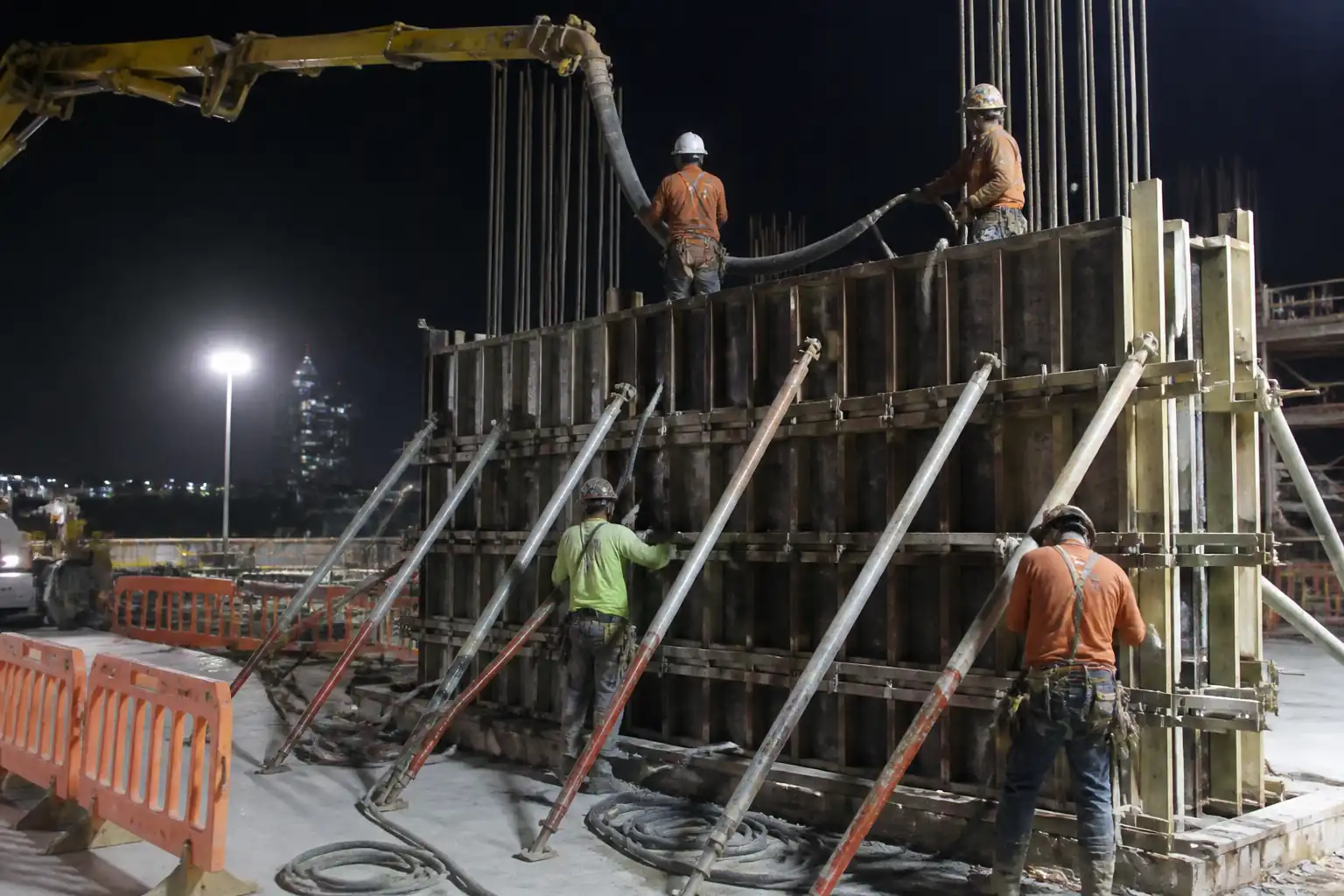
| 6 | Bracing and tying | Install plan/elevation bracing at specified intervals; fit wall/column ties per design; torque/tighten as required; install anti-uplift restraints. | Formwork Crew | TWS check |
| 7 | Openings, embeds, and interfaces | Install box-outs, sleeves, anchor templates, chamfers, waterstops as detailed. Coordinate with rebar and MEP. | Formwork Crew/MEP/Rebar | QA/QC |
| 8 | Application of release agent and surface prep | Clean and seal joints; apply release agent uniformly avoiding reinforcement. | Formwork Crew | Visual |
| 9 | Pre-pour survey and QA hold point | Full inspection of geometry, supports, bracing, connections, access/edge protection, pour plan; install tell-tales/deflection gauges if specified. TWC issues Permit-to-Load. | TWS/QA/QC/Site Engineer/TWC | Hold Point HP1 |
| 10 | Concrete placement and monitoring | Place concrete per pour plan; control rate-of-rise to limit form pressure; monitor temperature/slump; observe deflections/any distress; maintain exclusion zone. | Concrete Supervisor/TWS | Witness Point WP1 |
| 11 | Post-pour securing and curing interfaces | Maintain supports and bracing; check for settlement; repair any grout loss; maintain curing regime; record as-poured levels. | TWS/Concrete Supervisor | Post-pour check |
| 12 | Striking assessment and permit | Assess concrete strength by cylinders, cubes, or maturity; verify environmental conditions; plan striking sequence and back-propping; issue Permit-to-Strike. | TWD/TWC/QA | Hold Point HP2 |
| 13 | Strike and back-propping | Remove shutters in controlled sequence; transfer loads to back-props; maintain stability/edge protection; no prying that damages concrete; make good tie holes. | Formwork Crew under TWS | In-process |
| 14 | Removal of back-props and demobilization | Remove back-props once subsequent construction stages provide alternative load paths and concrete achieves required strength; clear site and store components. | TWC/TWS | Final inspection |
Safety Controls
Principal Hazards and Controls
- Hazard: Falsework/formwork instability or collapse during erection or pour.
- Likely consequence: Multiple serious injuries/fatality, structural damage.
- Engineering/procedural control: BS 5975-compliant procedure; engineered bracing plan; staged erection with temporary bracing; exclusion zones; Permit-to-Load; rate-of-rise limits to control pressure per ACI 347/EN 13670; continuous supervision by TWS.
- Required PPE: Hard hat, safety boots, gloves, eye protection.
- Collective preventive measure: Edge protection, catch platforms, debris netting where applicable.
-
Inspection/permit/supervision: Daily TWS inspection; HP1 before pour; WP1 during pour; calibrated tools; TWC authorization.
-
Hazard: Working at height (erection/striking).
- Likely consequence: Falls leading to serious injury/fatality.
- Engineering/procedural control: Prefabricate at ground where possible; use MEWPs/scaffold with full guardrails; maintain 3-point attachment; use certified anchor points for fall arrest only as last resort [Verify per project HSE plan].
- Required PPE: Full body harness with double lanyard when required, hard hat with chin strap, non-slip boots.
- Collective preventive measure: Temporary platforms with toeboards and midrails to EN 13374/OSHA equivalent.
-
Inspection/permit/supervision: Working at Height permit; daily checks of platforms; competent MEWP operator.
-
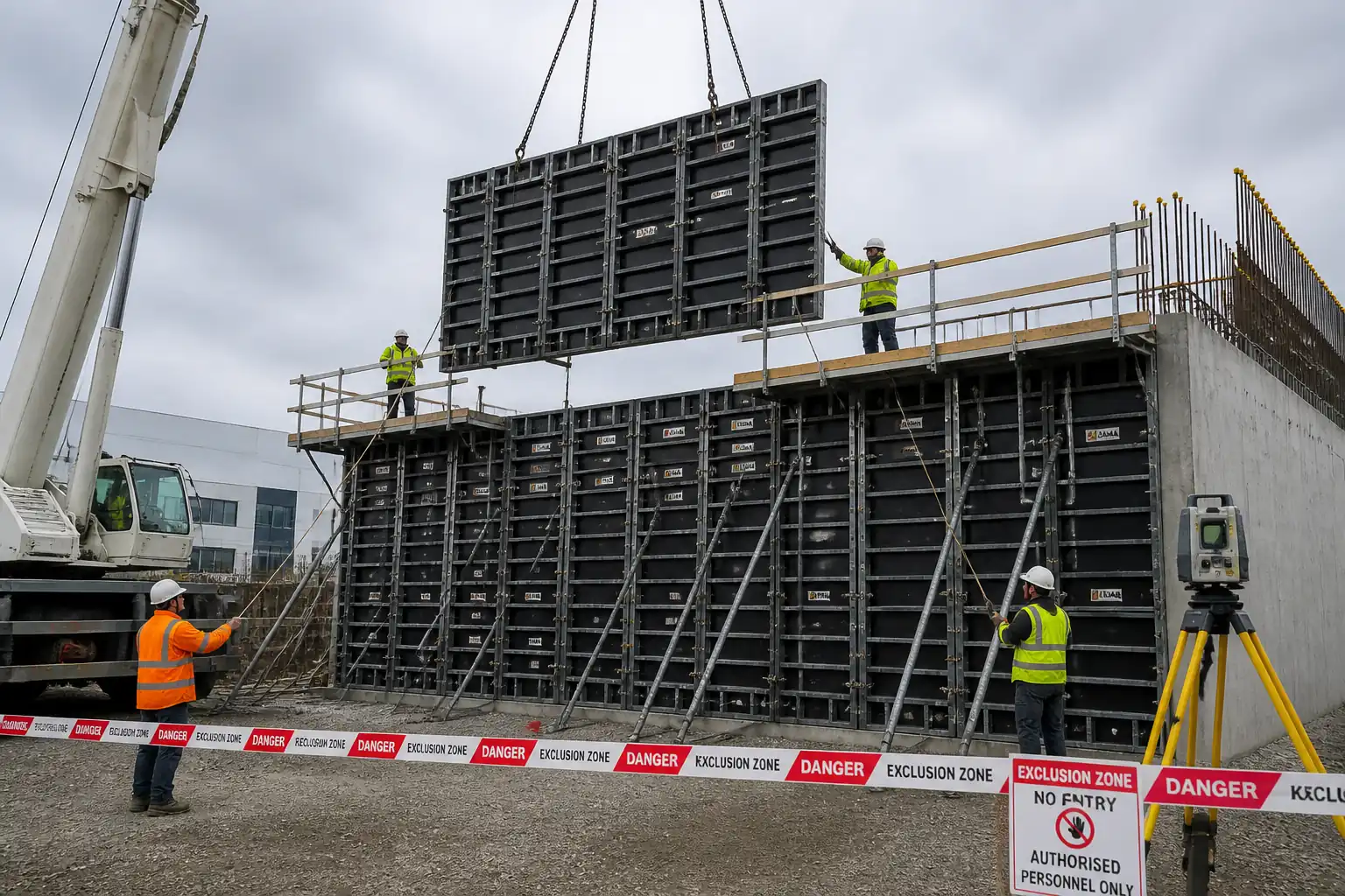
Hazard: Lifting operations for panels/beams.
- Likely consequence: Crush injuries, dropped loads.
- Engineering/procedural control: Appointed person lift plan; certified lifting points; taglines; no personnel under suspended loads; wind limits observed.
- Required PPE: Helmets with chin straps, gloves, high-vis, safety boots.
- Collective preventive measure: Exclusion zones with barriers and banksman control.
-
Inspection/permit/supervision: LOLER/third-party certifications; pre-lift checklist; banksman in control.
-
Hazard: Ground failure under soleplates/props.
- Likely consequence: Sudden settlement and collapse.
- Engineering/procedural control: Geotechnical verification; adequate soleplate sizing; avoid services/voids; monitor for settlement with tell-tales.
- Required PPE: Standard site PPE.
- Collective preventive measure: Barricade area; distribute loads via grillage if needed.
-
Inspection/permit/supervision: TWS verification; records of bearing checks; HP1 prior to loading.
-
Hazard: Contact with rebar ends, sharp edges, or pinch points.
- Likely consequence: Lacerations, hand injuries.
- Engineering/procedural control: Rebar caps; safe handling; mechanical aids; pinch-point awareness; use of push sticks.
- Required PPE: Cut-resistant gloves, long sleeves, safety glasses.
- Collective preventive measure: Guarding of moving parts on tools; housekeeping.
-
Inspection/permit/supervision: Tool inspections; supervisor monitoring.
-
Hazard: Electrical contact with overhead/adjacent lines (crane/MEWP).
- Likely consequence: Electrocution, arc flash.
- Engineering/procedural control: Exclusion distances; isolation/permit from utility owner; spotter assigned.
- Required PPE: Dielectric gloves if required, arc-rated clothing where specified.
- Collective preventive measure: Physical barriers and signage.
-
Inspection/permit/supervision: Electrical proximity permit; supervision by AP.
-
Hazard: Noise and vibration from tools.
- Likely consequence: Hearing loss, hand-arm vibration.
- Engineering/procedural control: Select low-vibration tools; task rotation; exposure monitoring.
- Required PPE: Hearing protection; anti-vibration gloves where appropriate.
- Collective preventive measure: Acoustic screens if near sensitive receptors.
-
Inspection/permit/supervision: HSE monitoring; maintenance logs.
-
Hazard: Chemical exposure to form release agents.
- Likely consequence: Dermatitis, respiratory irritation.
- Engineering/procedural control: Use low-VOC products; decant in controlled areas; avoid overspray; provide SDS and training.
- Required PPE: Nitrile gloves, goggles, long sleeves, respiratory protection where required [Verify].
- Collective preventive measure: Spill kits and drip trays.
-
Inspection/permit/supervision: COSHH/chemical handling permit [Verify per project HSE plan and local regulations].
-
Hazard: Striking and falling objects during dismantling.
- Likely consequence: Head injuries, fractures.
- Engineering/procedural control: Controlled zones; progressive release of loads; tool lanyards; no striking from below.
- Required PPE: Hard hat, eye/face protection, gloves.
- Collective preventive measure: Exclusion zone and overhead protection where necessary.
-
Inspection/permit/supervision: Permit-to-Strike; TWS oversight.
-
Hazard: Adverse weather (wind/rain/heat).
- Likely consequence: Loss of control, slips, reduced material strength of timber when saturated.
- Engineering/procedural control: Monitor weather; suspend operations per limits; cover materials; non-slip surfaces; hydration and heat stress plan.
- Required PPE: Weather-appropriate PPE.
- Collective preventive measure: Temporary shelters; dewatering as needed.
- Inspection/permit/supervision: Supervisor weather briefings.
Environmental Controls
Environmental Risks and Controls
- Form oil and chemical spills
- Control: Store in bunded trays; use spill kits; train operators; avoid over-application; designated refilling area.
-
Monitoring: Weekly environmental inspections; spill log.
-
Timber/plywood waste and damaged components
- Control: Maximize reuse; segregate clean timber; return-to-supplier schemes; cut optimization plans.
-
Monitoring: Waste transfer notes; reuse rate KPI.
-
Noise and dust from cutting/hammering
- Control: Off-site pre-cutting where possible; dust extraction and wet cutting; acoustic screens; limit hours near receptors [Verify per permit].
-
Monitoring: Spot noise/dust measurements.
-
Concrete washout and slurry during pour
- Control: Dedicated lined washout; prevent discharge to drains; capture laitance; manage pump blow-outs.
-
Monitoring: Visual checks during and after pour.
-
Transport and storage footprint
- Control: Just-in-time deliveries; defined laydown on geotextile; protect vegetation/soil; drip trays under parked plant.
- Monitoring: Delivery logs; site walkdowns.
QA/QC
Quality Objectives
- Ensure temporary works meet design intent, are safe to load, and produce permanent works within specified tolerances and finish class.
Controls and Records
- Design control: Approved TWD drawings/calcs; independent check records; change control via TQ/RFI.
- Materials control: Certificates for props (EN 1065 class), plywood (EN 636/13986), ties/anchors; visual inspection for damage; batch traceability.
- Assembly control: ITP with 100% checks at HP1; torque/engagement of connections per manufacturer [Verify]; survey of critical geometry.
- Monitoring: During pour, record rate-of-rise, temperature, slump, deflection/settlement where specified.
- Nonconformance: Raise NCR for deviations; implement corrective actions; re-inspection prior to loading.
- Measuring and testing equipment: Calibration certificates current for survey kit, torque wrenches, thermometers.
- Document retention: Permits (Erect/Load/Strike), checklists, survey reports, photos, test results, as-built sketches retained per project QA plan.
Tolerances [Verify per project specifications]
- Soffit level: ±5 mm over bay length ≤ 10 m; otherwise ±10 mm.
- Plan dimensions/openings: ±10 mm typical.
- Verticality/plumb: ≤ 1/500 or 5 mm in 3 m (whichever greater).
- Deflection under wet concrete and construction loads: ≤ L/400 (slab/beam soffit) unless TWD specifies otherwise.
Fresh Concrete Pressure (Walls/Columns)
- Determine per ACI 347 or EN 13670 considering rate-of-rise, temperature, unit weight, slump, and admixtures. Designer to set allowable pour rate; typical limits 1–2 m/h for normal-weight mixes at 10–25°C [Verify per mix and system].
Attachments
- Sample Permit-to-Erect / Permit-to-Load / Permit-to-Strike templates.
- Pre-pour Formwork/Falsework Checklist (HP1).
- Pour Monitoring Log (rate-of-rise, temperature, slump, deflections).
- Striking/Back-propping Checklist (HP2).
- Daily Falsework Inspection Log.
- Lift Plan and Rigging Sketch (if applicable).
- Manufacturer technical data sheets (props, beams, ties, panels).
- Design drawings and calculation package including assumed loads and tolerances.
This content is a read-only public reference. Download or customize to get an editable version.
ITP preview
The first inspection activities from the linked ITP for Method Statement: Temporary Formwork and Falsework Support System for Reinforced Concrete Structural Elements:
| Activity | Inspection / Test | Acceptance Criteria | Responsibility | Record |
|---|---|---|---|---|
| Design submission and independent check | Review of drawings/calcs vs BS 5975/EN 12812/ACI 347 | Design approved; category check completed [Verify] | TWD/TWC | Approved design; check certificate |
| Material verification on delivery | Certificates, visual condition | Correct grades/classes; undamaged; traceable | QA/QC | Delivery inspection report; CoC |
| Ground/soffit bearing capacity check | Plate load test or calculation review | Allowable bearing ≥ design reaction with FS ≥ 2.0 [Verify] | Site Engineer/TWS | Bearing calc/test record |
Showing 3 of 12 inspection activities. View full ITP →
Related Inspection and Test Plan
An Inspection and Test Plan (ITP) is available for Method Statement: Temporary Formwork and Falsework Support System for Reinforced Concrete Structural Elements. The ITP defines the inspection activities, acceptance criteria, hold and witness points, responsible parties, and records required to verify the work described in this method statement.
View the Method Statement: Temporary Formwork and Falsework Support System for Reinforced Concrete Structural Elements ITP →Frequently asked questions
Continue with related Quollnet resources connected to this method statement.