Method Statement: Erection and Shifting of Modular Slab Soffit Table Formwork Systems – Method Statement
AI-assisted method statement with matching ITP, PDF download, and Excel export.
More than a static template
Unlike a downloadable Word or PDF template, this method statement is an AI-assisted editable starting point connected directly to a matching Inspection and Test Plan. Every section is structured, project-adaptable, and ready to export.
- AI-assisted drafting — Customize every section with AI for your specific project scope.
- Linked ITP — A matching inspection and test plan is generated alongside the method statement.
- Multiple export formats — Download as a formatted PDF or editable Excel spreadsheet.
- Editable starting point, not a final document — Review, verify, and adjust all content against your project requirements before use.
Static template vs. Quollnet workflow
| Feature | Static template | Quollnet |
|---|---|---|
| Project-specific content | Manual fill-in required | AI-assisted customization |
| Linked ITP | Separate document, no link | Matching ITP included |
| Export formats | Usually PDF only | PDF and Excel |
| Structured sections | Free-form layout | 13 standardized sections |
| Saved to your account | Local file only | Cloud-saved, reusable |
| Content accuracy | You verify everything | AI-assisted, you still verify |
| Cost | Often free but time-intensive | Free to customize and download |
What you can customize
When you save this method statement to your account, every section becomes editable. The following 13 sections are included:
- Scope — Defines the activity and its boundaries.
- References — Standards, specifications, and drawings.
- Responsibilities — Roles and accountabilities.
- Resources — Labour, plant, and equipment summary.
- Materials — Materials and compliance requirements.
- Equipment — Tools and equipment details.
- Prerequisites — Hold points and pre-conditions.
- Method sequence — Step-by-step construction sequence.
- Safety controls — HSE risk controls and PPE.
- Environmental controls — Environmental mitigation measures.
- QA/QC — Quality inspection and test requirements.
- ITP — Inspection and Test Plan table (has its own page).
- Attachments — Referenced drawings and documentation.
Why this method statement is used
This method statement is used to define and communicate the approved procedure for carrying out method statement: erection and shifting of modular slab soffit table formwork systems on site. It ensures the work is planned in advance, the correct resources and controls are in place, and all personnel understand responsibilities, sequence, quality requirements, and safety controls before work begins. It aligns site execution with the documented scope and acceptance expectations.
Who uses this method statement
This method statement is used by contractors, site supervisors, project engineers, QA/QC engineers, HSE officers, consultants, and client representatives. It serves as a shared reference for planning, execution, supervision, inspection, and approval of the activity on site.
When it is prepared and submitted
The method statement is prepared before the work activity starts and submitted as part of the pre-construction documentation package for review and approval.
Who reviews or approves it
The method statement is usually submitted to the client representative, consultant, resident engineer, or project management consultant for review and approval before the work commences.
Important approval note
This method statement is an AI-assisted editable starting point, not a pre-approved document. Before use on any project, all content must be reviewed and approved by the relevant parties (superintendent, principal contractor, or client representative) in accordance with your contract and project quality plan.
For example: if your specification requires a departure from a referenced standard, that departure must be documented and approved separately — this method statement will not capture that automatically. Always verify against your applicable drawings, specifications, and regulatory requirements.
Method statement content
Scope
Overview
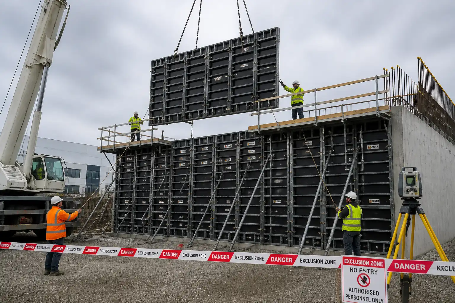
This method statement covers planning, fabrication, erection, alignment, inspection, concreting support, early striking using drop-heads, and shifting/rolling/flying of modular slab soffit table formwork systems for cast-in-place reinforced concrete slabs. It includes:
- Setting-out and installation of drop-head shores, primary and secondary beams/joists, and plywood decking.
- Installation and verification of perimeter/leading-edge guardrails and toe boards.
- Pre-pour and post-pour inspections, including deflection and level control.
- Early striking with drop-heads, re-shoring, and mechanical table shifting/rolling or crane flying between bays.
- QA/QC controls, HSE controls, and records/ITP requirements.
Exclusions
- Column/wall formwork (covered under separate method).
- Permanent works design; only implements the approved Temporary Works Design (TWD). Any changes require TWD re-approval.
Key Performance Targets [Verify per project specifications]
- Soffit level tolerance: ±5 mm over 3 m; ±10 mm over bay.
- Prop plumb tolerance: ≤1/200; base settlement ≤5 mm (no progressive settlement).
- Deflection under self-weight + wet concrete + construction live load: ≤L/500 (unless TWD states otherwise).
- Beam and joist spacing installed to TWD; typical ranges indicated herein are for guidance only.
References
| Document Type | Reference / Number | Revision | Notes |
|---|---|---|---|
| Standard | ACI 347 | ||
| Standard | BS 5975 | ||
| Standard | EN 12812 | ||
| Standard | EN 1992-1-1 / ACI 318 | ||
| Standard | EN 13374 / OSHA 1910.29 | ||
| Standard | EN 13986 / EN 636 / ASTM PS1/PS2 | ||
| Standard | ISO 9001 / ISO 45001 / ISO 14001 |
Responsibilities
| Role | Responsibility | Name / Party |
|---|---|---|
| Project Manager | ||
| TWC | ||
| TWD | ||
| Site Engineer | ||
| Formwork Foreman | ||
| HSE Manager/Officer | ||
| Lifting Supervisor | ||
| QA/QC Engineer | ||
| Edge Protection Supervisor | ||
| Supplier Rep |
Resources
| Resource Type | Description | Quantity | Remarks |
|---|---|---|---|
| Manpower | Assembly, decking, alignment | As per workfront size | |
| Manpower | Assist rolling/flying and positioning tables | As per lifting plan | |
| Manpower | Work at height for leading edges and guardrails | 1–2 per bay [Verify] |
Materials
| Material | Specification / Grade | Quantity | Remarks |
|---|---|---|---|
| Aluminum/steel/timber | Per supplier datasheet | ||
| Birch/radiata | E1 emission | ||
| Steel/aluminum | EN 12812-compliant | ||
| Steel/aluminum/timber | Per system manual | ||
| Steel | Class 8.8 or per supplier | ||
| Mineral/vegetable-based | VOC limits [Verify] |
Equipment
| Equipment | Capacity / Type | Quantity | Inspection Required |
|---|---|---|---|
| 1 per workfront | Yes | ||
| As needed | Yes | ||
| Per table | Yes | ||
| As per plan | Yes | ||
| Per crew | Yes | ||
| As required | Yes |
Prerequisites
- Approved Temporary Works Design (TWD) and drawings for the specific floor/bay, including: leg loads, spacing of props/primary/secondary members, plywood grade/thickness, camber, re-shoring plan, early striking criteria, lifting/rolling configuration, and edge protection details.
- Temporary Works Register entry and permit workflow per BS 5975.
- Lifting Plan (if flying) approved by the Appointed Person; toolbox talk conducted.
- Structural engineer confirmation that early striking and re-shoring sequence align with structural design assumptions.
- Survey control: benchmark elevations and grid set-out completed and checked.
- Substrate verification for prop base capacity; sole boards provided where slab capacity or finishes require.
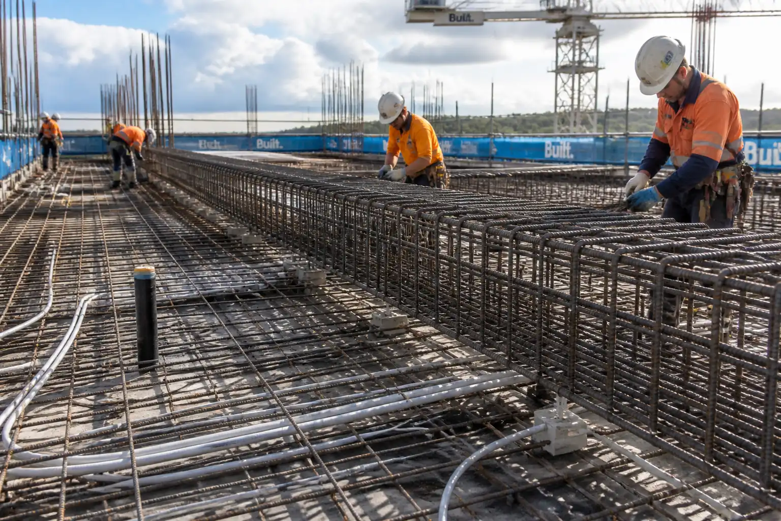
- Utilities/MEP and openings identified; penetrations and cast-in items coordinated.
- Material/component inspection on delivery; remove damaged or out-of-spec parts.
- HSE: risk assessment, method briefing, permits to work (work at height, lifting), housekeeping plan, exclusion zones planned.
- Weather and wind monitoring arrangements in place (anemometer if flying tables).
Method Sequence
| Step | Activity | Description | Responsibility | Inspection / Hold Point |
|---|---|---|---|---|
| 1 | Setting Out | Mark grid lines, slab edges, column/wall faces, and set elevation benchmarks at each bay. Identify table module sizes per TWD. | Site Engineer | Dimensional check |
| 2 | Pre-Assembly Area Preparation | Prepare safe flat area for table pre-assembly. Establish exclusion zone and material laydown. Verify lifting/rolling route clearances. | Formwork Foreman / HSE | Area inspection |
| 3 | Table Pre-Assembly (On Floor or Ground) | Assemble primary beams per TWD. Install secondary joists at specified c/c (typ. 300–600 mm). Fix plywood (18–21 mm) with screws (edge ~150 mm, field ~300 mm). Fit guardrail posts/toe boards on table perimeter where designed to travel with table. | Formwork Foreman | Visual; fastener pattern |
| 4 | Erect Drop-Head Shores/Props | Position props under primary beam nodes at TWD grid (typ. 1.2–1.8 m c/c). Install baseplates/sole boards. Plumb props (≤1/200). Adjust to level with screw jacks. Lock drop-heads engaged. | Formwork Foreman / Site Engineer | Plumb/level check |
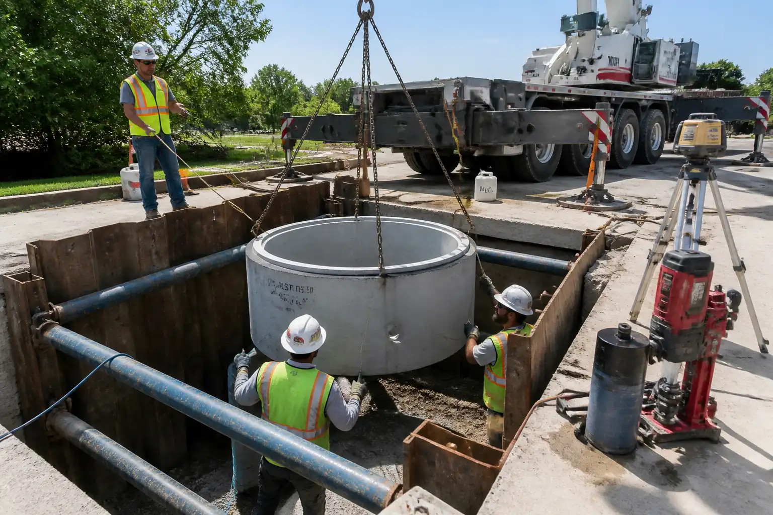
| 5 | Lift/Slide Table into Position | Option A rolling: fit castors, release brakes only when controlled; maintain leading-edge guardrails. Option B flying: rig to lifting frame, check sling angles and WLL, guide with tag lines. Position to marks; engage onto drop-heads. | Lifting Supervisor / Formwork Foreman | Pre-use checks; wind reading |
| 6 | Alignment, Leveling, and Camber | Fine-adjust screw jacks to achieve soffit level/camber per TWD (typ. camber L/500). Check joints are tight; seal gaps. Confirm load paths and bracing as designed. | Site Engineer | Laser level/straightedge |
| 7 | Perimeter Closures and Edge Protection | Install fixed guardrails (top 1.0–1.2 m, mid, toe ≥150 mm). Fit leading-edge system or temporary handrails ahead of pour line. Close slab edges, infills, and cantilevers with supplementary props/joists. | Edge Protection Supervisor / Formwork Foreman | Edge protection inspection |
| 8 | Pre-Pour Inspection and Permit to Load | Apply release agent thinly. Verify block-outs, MEP sleeves, pour sequence, access, lighting. Issue Permit to Load when TWD-compliant. | QA/QC Engineer / TWC | ITP hold point |
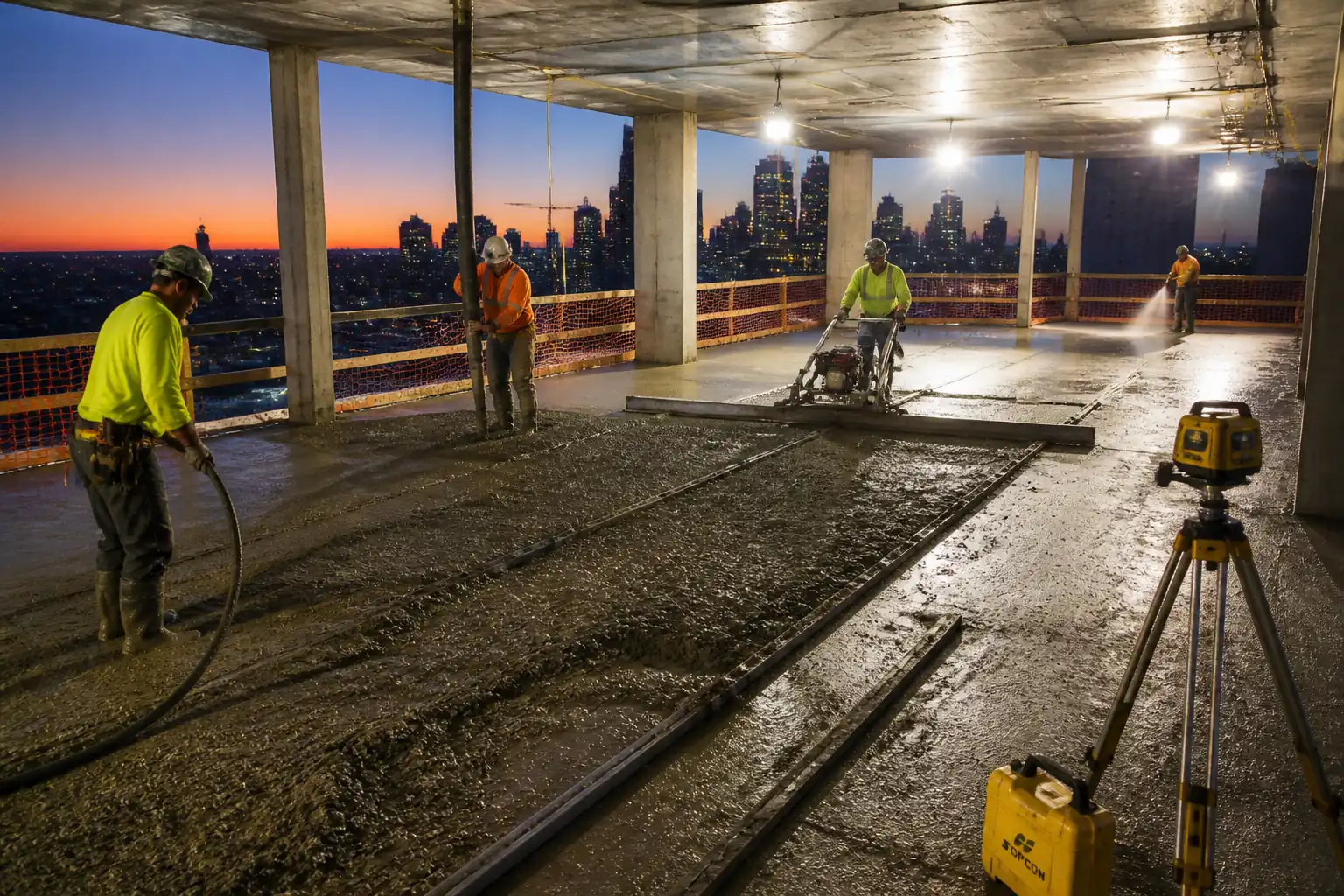
| 9 | Concrete Placement Support | Monitor during pour for deflection and stability. Keep travel pathways of pumps clear. Do not adjust props during pour. | Formwork Foreman / Site Engineer | Ongoing monitoring |
| 10 | Early Striking via Drop-Head | When concrete achieves minimum strength (typ. ≥10 MPa by cubes/maturity) and with TWC approval, release drop-head to lower secondary beams/plywood by ~100–150 mm. Leave props/re-shores as per plan. | TWC / QA/QC / Formwork Foreman | ITP hold/witness |
| 11 | Mechanical Shifting/Rolling of Tables | Fit castors; install leading-edge guardrail on table; verify route gradients ≤5%, edges protected, openings covered. Push with coordinated team or mechanical tug; brakes applied during pauses. | Formwork Foreman / HSE | Route inspection |
| 12 | Reset in Next Bay | Re-engage onto drop-heads, level, set camber, close perimeters; repeat pre-pour checks. | Formwork Foreman / Site Engineer | As Steps 4–8 |
| 13 | Final Striking and Re-shore Removal | After concrete reaches required strength per TWD/Engineer (typ. 75–100% fck depending on span and environment), remove remaining props and re-shores sequentially. | TWC / Structural Engineer / Foreman | ITP hold |
| 14 | Housekeeping and Demobilization | Clean and stack components; inspect for damage; repair/retire as needed. Update reuse counts for plywood. | Formwork Foreman / QA | Post-task inspection |
Safety Controls
Task-specific hazards and controls
- Hazard: Fall from height (leading edges, during erection/striking)
- Likely consequence: Serious injury or fatality
- Engineering/procedural control: Install edge protection (EN 13374 Class A/B) before removing any existing protection; use MEWP for leading edges; use temporary leading-edge guardrail mounted to table; forbid working outside protected zone; rescue plan in place.
- Required PPE: Hard hat, safety boots, gloves, eye protection; fall arrest harness with double lanyard when required.
- Collective preventive measure: Fixed guardrails and toe boards; safety nets where specified.
-
Inspection/permit/supervision: Daily edge protection inspection; Work at Height PTW; HSE supervision. [Verify per project HSE plan and local regulations]
-
Hazard: Formwork collapse/overload due to mis-spacing or premature strike
- Likely consequence: Structural failure, injury, damage
- Engineering/procedural control: Strict adherence to TWD spacings and leg loads; Permit to Load/Strike; do not exceed additional imposed load beyond TWD; re-shoring per plan; monitor deflection; no adjustment during pour.
- Required PPE: Standard PPE; hearing protection during fixing.
- Collective preventive measure: Exclusion zones; signage; barricades during pour/strike.
-
Inspection/permit/supervision: ITP hold points; TWC approval; QA inspections; calibrated level readings.
-
Hazard: Lifting/rolling table instability; dropped loads
- Likely consequence: Crush injuries, property damage
- Engineering/procedural control: Approved Lifting Plan; WLL verification; wind threshold typically ≤10 m/s (flying); use tag lines; for rolling, keep gradient ≤5%, use brakes/chocks, mechanical tug if push force excessive.
- Required PPE: Helmets with chin straps, gloves; high-visibility vests; safety boots.
- Collective preventive measure: Exclusion zones under suspended loads; banksman control; route guards.
-
Inspection/permit/supervision: Lifting permits; pre-use inspections; Appointed Person/Lifting Supervisor present.
-
Hazard: Prop base punch-through/settlement
- Likely consequence: Loss of support, deck differential settlement
- Engineering/procedural control: Verify slab capacity and provide sole boards; ensure full bearing and no debris under baseplates; avoid puddles/slurry; periodic recheck after initial loading.
- Required PPE: Standard PPE.
- Collective preventive measure: Spreaders/sole boards for weak substrates.
-
Inspection/permit/supervision: Base checks each shift; Site Engineer sign-off.
-
Hazard: Pinch/crush points during drop-head release and rolling
- Likely consequence: Hand injuries
- Engineering/procedural control: Use tool-assisted release; hands clear of pinch zones; communicate countdown; only trained personnel operate drop-heads.
- Required PPE: Cut-resistant gloves.
- Collective preventive measure: Mark pinch points; brief team.
-
Inspection/permit/supervision: Foreman oversight; toolbox talks.
-
Hazard: Contact with overhead services or building façade during flying
- Likely consequence: Strikes, utility damage
- Engineering/procedural control: Survey clearance envelope; spotters; temporary removal of obstructions; lock-out of nearby equipment as needed.
- Required PPE: Standard PPE.
- Collective preventive measure: Exclusion zones; banksmen; tag lines.
-
Inspection/permit/supervision: Pre-lift meeting; permit; supervision throughout.
-
Hazard: Slips/trips on deck (oil, offcuts, protruding screws)
- Likely consequence: Sprains, minor injuries
- Engineering/procedural control: Controlled application of release agent; housekeeping after each shift; remove/flush protruding fasteners.
- Required PPE: Slip-resistant boots, gloves.
- Collective preventive measure: Good lighting; waste chutes; material boxes.
-
Inspection/permit/supervision: HSE walkdowns; closeout checklists.
-
Hazard: Noise and vibration from power tools
- Likely consequence: Hearing loss, HAVS
- Engineering/procedural control: Use low-noise tools; limit exposure time; maintain equipment.
- Required PPE: Ear protection; anti-vibration gloves as appropriate.
- Collective preventive measure: Job rotation; quiet hours scheduling.
-
Inspection/permit/supervision: HSE monitoring.
-
Hazard: Manual handling of panels/joists
- Likely consequence: Musculoskeletal injury
- Engineering/procedural control: Team lifts; mechanical aids; keep within weight limits; pre-assemble into manageable sizes.
- Required PPE: Gloves; back support if specified.
- Collective preventive measure: Use trolleys/castors; plan lifts.
- Inspection/permit/supervision: Foreman supervision; manual handling training records.
Environmental Controls
- Release agent management: Use low-VOC products where practicable; apply with controlled sprayers/rollers; prevent overspray; store with secondary containment; spill kits at point of use. [Verify per project HSE plan and local regulations]
- Waste minimization: Maximize reuse of plywood and beams; track reuse count; segregate waste (timber, metal, general). Return damaged proprietary items to supplier for repair/recycling.
- Noise control: Schedule high-noise activities during permitted hours; maintain tools; use acoustic screens near sensitive receptors.
- Dust control: Cut timber in designated area with dust extraction; sweep, not blow; dampen as needed.
- Water protection: Prevent slurry, wash water, and oils from entering drains; use drip trays; no washing tools over open ground.
- Energy/emissions: Optimize crane/MEWP usage; switch off idling equipment; plan rolling routes to reduce handling.
- Material sourcing: Use certified timber (FSC/PEFC) where contractually required.
- Light pollution: Use directed task lighting; avoid spill outside site boundary at night.
- Incident response: Report and record any spill or environmental incident; implement corrective actions.
QA/QC
Controls and Records
- Temporary Works approvals: TWD calculations and drawings approved by Designer and TWC; register entry completed.
- Component verification: Check certificates, WLL markings, condition; quarantine damaged components.
- Calibration: Maintain calibration for laser/levels (≤6 months) and lifting gear inspections (per statutory period) [Verify per project].
- Inspection frequency: 100% checks at pre-pour and at each move/reset; daily visual checks of props, heads, guardrails.
- Fastener control: Verify screw size/spacing matches TWD and plywood spec; avoid overdriving; remove protrusions.
- Level/camber: Record level grid checks per bay; deflection checks during first pour or as directed by TWD.
- Permits: Permit to Load, Permit to Strike, Lifting Permit retained in QA file.
- Concrete strength evidence: Use cube tests or maturity curves linked to batch and pour location for early strike and final strike approvals.
- Nonconformance: Raise NCR for deviations; implement corrective actions and re-inspect.
- As-built: Record any approved deviations and update redlines for future cycles.
- Training/competence: Maintain records of crew training on system formwork and drop-head operations.
Attachments
- Sample checklists:
- Table pre-assembly checklist
- Prop/drop-head layout and base bearing checklist
- Edge protection inspection checklist
- Pre-pour ITR and Permit to Load form
- Early strike Permit to Strike form
- Table shifting/rolling checklist
- Final strike checklist
- Typical TWD drawings and details (leg load schedule, spacing tables, camber profile, re-shoring plan)
- Lifting plan and rigging sketches (if flying)
- MSDS for release agents
- Manufacturer’s manuals for proprietary systems and drop-head operation
- Toolbox talk templates (leading edges, drop-head release, rolling operations)
This content is a read-only public reference. Download or customize to get an editable version.
ITP preview
The first inspection activities from the linked ITP for Method Statement: Erection and Shifting of Modular Slab Soffit Table Formwork Systems:
| Activity | Inspection / Test | Acceptance Criteria | Responsibility | Record |
|---|---|---|---|---|
| TWD Approval and Briefing | Review and sign-off of calculations/drawings; team briefing | Approved documents; personnel briefed; Temporary Works Register updated | TWC / TWD / PM | Approved TWD; briefing attendance; TWR entry |
| Material/Component Receipt Inspection | Visual check; verify certificates and WLL; check drop-head function | Conforming components; no damage/deformation; certificates present | QA/QC Engineer / Formwork Foreman | Material receiving ITR; photos |
| Setting Out Verification | Check gridlines and levels | Within ±5 mm of control; elevations confirmed | Site Engineer / QA | Survey records |
Showing 3 of 14 inspection activities. View full ITP →
Related Inspection and Test Plan
An Inspection and Test Plan (ITP) is available for Method Statement: Erection and Shifting of Modular Slab Soffit Table Formwork Systems. The ITP defines the inspection activities, acceptance criteria, hold and witness points, responsible parties, and records required to verify the work described in this method statement.
View the Method Statement: Erection and Shifting of Modular Slab Soffit Table Formwork Systems ITP →Frequently asked questions
Continue with related Quollnet resources connected to this method statement.