Method Statement: Installation of Precast Concrete Sewerage Manholes – Method Statement
AI-assisted method statement with matching ITP, PDF download, and Excel export.
More than a static template
Unlike a downloadable Word or PDF template, this method statement is an AI-assisted editable starting point connected directly to a matching Inspection and Test Plan. Every section is structured, project-adaptable, and ready to export.
- AI-assisted drafting — Customize every section with AI for your specific project scope.
- Linked ITP — A matching inspection and test plan is generated alongside the method statement.
- Multiple export formats — Download as a formatted PDF or editable Excel spreadsheet.
- Editable starting point, not a final document — Review, verify, and adjust all content against your project requirements before use.
Static template vs. Quollnet workflow
| Feature | Static template | Quollnet |
|---|---|---|
| Project-specific content | Manual fill-in required | AI-assisted customization |
| Linked ITP | Separate document, no link | Matching ITP included |
| Export formats | Usually PDF only | PDF and Excel |
| Structured sections | Free-form layout | 13 standardized sections |
| Saved to your account | Local file only | Cloud-saved, reusable |
| Content accuracy | You verify everything | AI-assisted, you still verify |
| Cost | Often free but time-intensive | Free to customize and download |
What you can customize
When you save this method statement to your account, every section becomes editable. The following 13 sections are included:
- Scope — Defines the activity and its boundaries.
- References — Standards, specifications, and drawings.
- Responsibilities — Roles and accountabilities.
- Resources — Labour, plant, and equipment summary.
- Materials — Materials and compliance requirements.
- Equipment — Tools and equipment details.
- Prerequisites — Hold points and pre-conditions.
- Method sequence — Step-by-step construction sequence.
- Safety controls — HSE risk controls and PPE.
- Environmental controls — Environmental mitigation measures.
- QA/QC — Quality inspection and test requirements.
- ITP — Inspection and Test Plan table (has its own page).
- Attachments — Referenced drawings and documentation.
Why this method statement is used
This method statement is used to define and communicate the approved procedure for carrying out method statement: installation of precast concrete sewerage manholes on site. It ensures the work is planned in advance, the correct resources and controls are in place, and all personnel understand responsibilities, sequence, quality requirements, and safety controls before work begins. It aligns site execution with the documented scope and acceptance expectations.
Who uses this method statement
This method statement is used by contractors, site supervisors, project engineers, QA/QC engineers, HSE officers, consultants, and client representatives. It serves as a shared reference for planning, execution, supervision, inspection, and approval of the activity on site.
When it is prepared and submitted
The method statement is prepared before the work activity starts and submitted as part of the pre-construction documentation package for review and approval.
Who reviews or approves it
The method statement is usually submitted to the client representative, consultant, resident engineer, or project management consultant for review and approval before the work commences.
Important approval note
This method statement is an AI-assisted editable starting point, not a pre-approved document. Before use on any project, all content must be reviewed and approved by the relevant parties (superintendent, principal contractor, or client representative) in accordance with your contract and project quality plan.
For example: if your specification requires a departure from a referenced standard, that departure must be documented and approved separately — this method statement will not capture that automatically. Always verify against your applicable drawings, specifications, and regulatory requirements.
Method statement content
Scope
Overview
This method covers the end-to-end installation of precast concrete sewerage manholes, including:
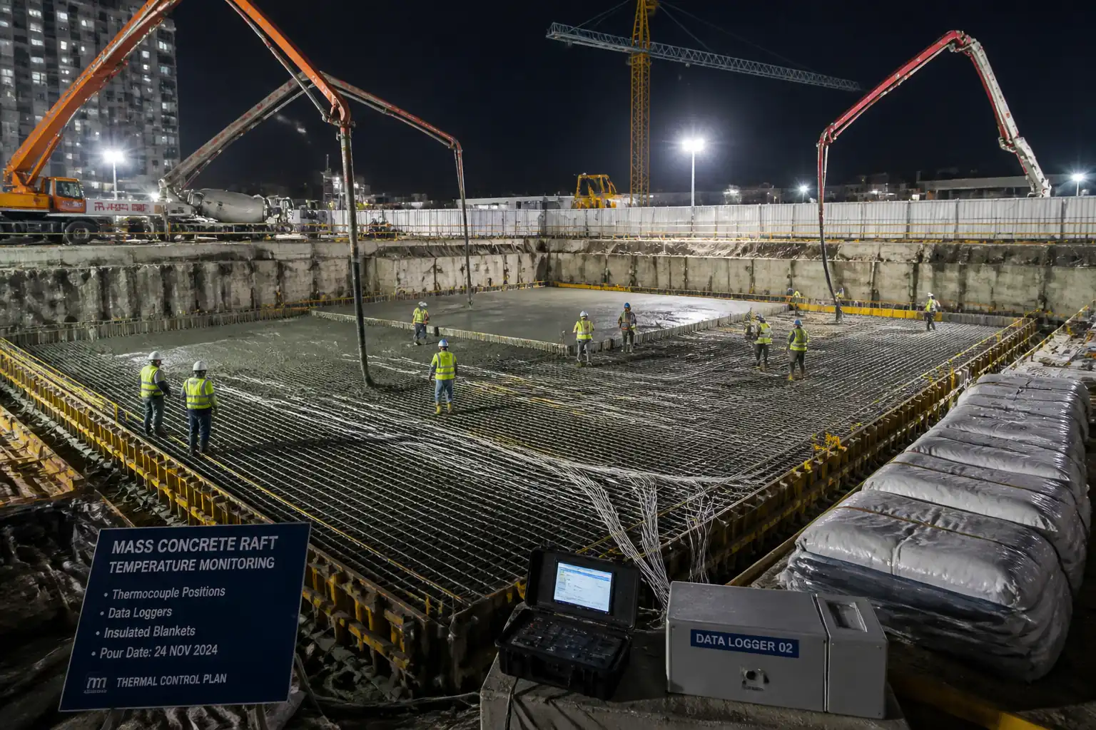
- Subgrade preparation, blinding, and in-situ reinforced concrete base slab (where a precast base is not used).
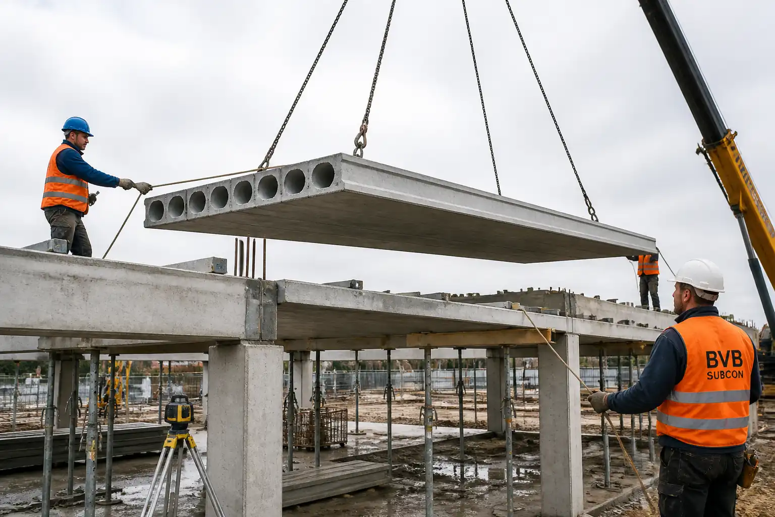
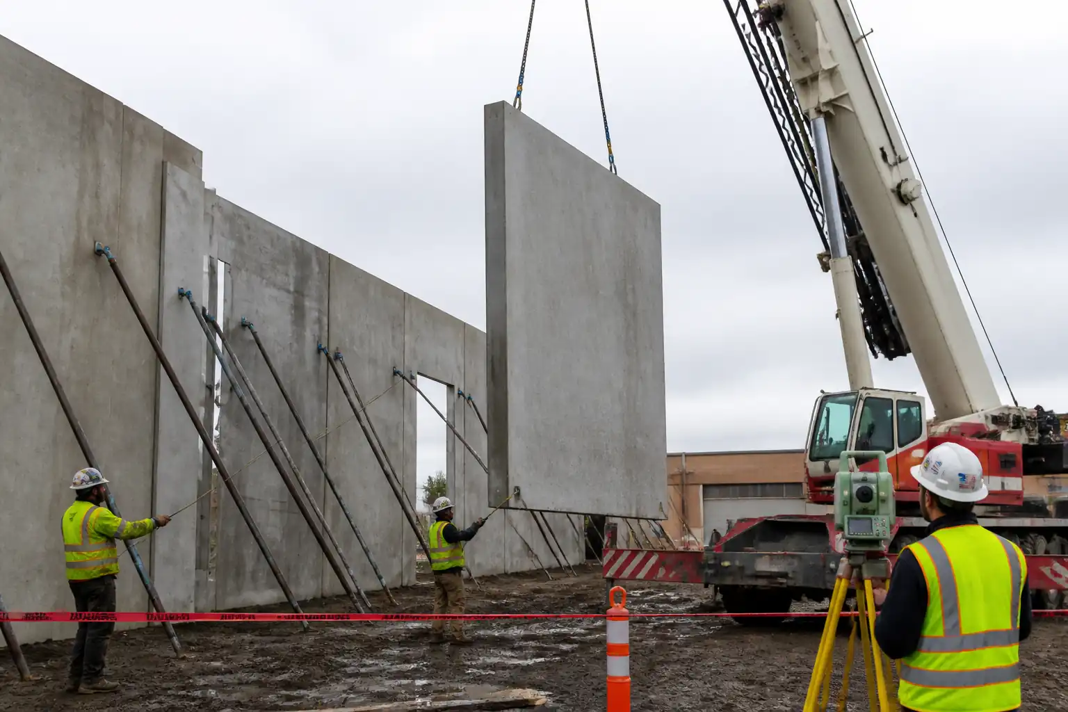
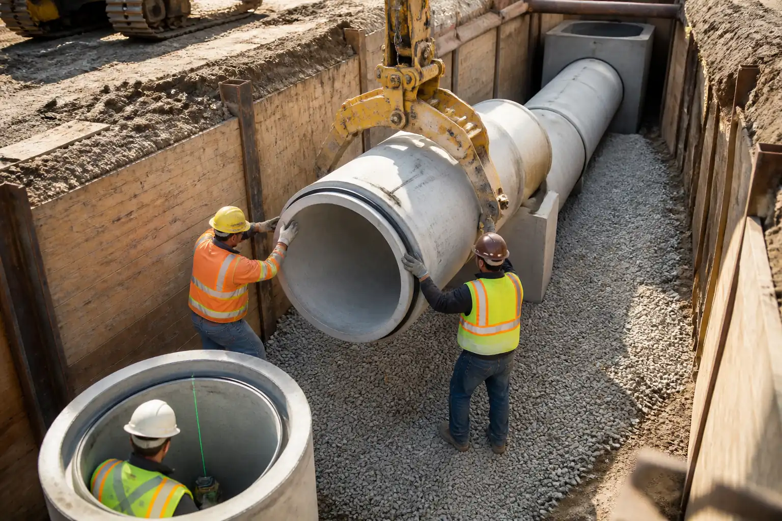
- Delivery, inspection, lifting, and stacking of precast manhole rings/cones/slabs.
- Joint preparation and sealing using hydrophilic waterstops (and/or gaskets) per manufacturer instructions.
- Formation of pipe connection openings by core drilling and installation of flexible boots or hydrophilic mortar seals.
- Application of internal and/or external waterproofing coating systems.
- Final level adjustments for frame and cover, benching/haunching as required, and as-built survey.
Exclusions
- Bulk excavation and shoring design/installation (covered by separate method unless specifically noted here for interface controls).
- Permanent diversion/over-pumping operations.
- Road reinstatement beyond frame and cover seating area.
Key Performance Targets [Verify per project specifications]
- Base slab level tolerance: ±5 mm; surface flatness ≤5 mm under 2 m straightedge.
- Manhole stack verticality: deviation ≤10 mm overall and ≤1:400.
- Ring joint gap uniformity: per manufacturer, typically 3–10 mm.
- Subgrade/bedding compaction: ≥95% MDD (ASTM D698) or ≥98% MDD for granular bedding/backfill layers, as specified.
- Waterproofing total DFT (cementitious): 1.5–2.0 mm in two coats; pinhole-free.
- Watertightness: per EN 1610 or ASTM C1244 acceptance criteria. [Verify per project]
- Cover/frame level tolerance: ±5 mm to finished surface; seating mortar bed 10–20 mm unless specified otherwise.
References
| Document Type | Reference / Number | Revision | Notes |
|---|---|---|---|
| Standard | BS EN 1610 | Testing options include air or water tests. [Verify per project] | |
| Standard | EN 1917; BS 5911-3 | For UK/EU projects; use ASTM C478 for US. | |
| Standard | ASTM C478 | For US-based projects. | |
| Standard | ASTM C923; BS EN 681-1 | Select per regional standard. | |
| Standard | ASTM C1244 | Acceptance limits per standard/manufacturer. [Verify per project] | |
| Standard | ACI 318; ACI 301 | Covers reinforcement, cover, placement, curing. | |
| Standard | ASTM D698; ASTM D1557 | Test method selection per specification. | |
| Standard | BS 5975 | TW design and CAT checks as applicable. | |
| Standard | BS EN 1504-2; EN 14891 | Select per approved waterproofing system. | |
| Standard | BS 7121; EN 13155; ISO 9927-1 | For lifting planning and gear certification. |
Responsibilities
| Role | Responsibility | Name / Party |
|---|---|---|
| PM | Ensure compliance with contract and program. | Contractor |
| Engineer | Verify levels, alignments, and interfaces. | Contractor |
| QA/QC | Raise/check ITRs, NCRs, ensure traceability. | Contractor |
| HSE | Ensure HSE controls implemented and monitored. | Contractor |
| Lifting | Authorize lifts, supervise rigging crew. | Contractor |
| Survey | Provide benchmarks and survey records. | Contractor |
| Foreman | Ensure workmanship and correct materials. | Contractor |
| Vendor | Provide installation guidance and approvals. | Supplier |
| Engineer | Approve ITP, method, inspections as required. | Employer/Engineer |
Resources
| Resource Type | Description | Quantity | Remarks |
|---|---|---|---|
| Manpower | 1 Foreman, 2 Riggers, 1 Crane Operator, 1 Banksman, 3 Skilled Workers, 2 Laborers, 1 Waterproofing Applicator, 1 QA/QC, 1 HSE Officer, 1 Surveyor (as required). | ~12–14/day | |
| Temporary Works | Trench/excavation support system per design; access/egress ladders; platforms. | As per design |
Materials
| Material | Specification / Grade | Quantity | Remarks |
|---|---|---|---|
| RC Precast | As per BOQ | ||
| Concrete | As designed | ||
| Rebar | As per drawings | ||
| Concrete | As required | ||
| Waterstop | As required | ||
| Gasket/Sealant | As required | ||
| Rubber + SS clamps | As required | ||
| Grout | As required | ||
| Coating | As required |
Equipment
| Equipment | Capacity / Type | Quantity | Inspection Required |
|---|---|---|---|
| Crane | As required | 1 | |
| Slings/Shackles | Set | ||
| Excavator/Compactor | As needed | ||
| Concrete tools | Set | ||
| Survey | Set | ||
| Core drill | 1 | ||
| CSE kit | Set | ||
| Pumps | As required |
Prerequisites
- Approved method statement, ITP, material submittals, lifting plan, and temporary works design.
- Permits: Excavation, Lifting, Confined Space Entry (if any internal works), Hot Works (if cutting steel), Dewatering/Discharge. [Verify per project HSE plan and local regulations]
- Utility clearance (GPR/records) and permit to dig; trial holes as required.
- Verified survey controls and benchmark; design invert/cover levels issued for construction.
- Ground bearing capacity verified for crane outriggers and working platforms; mats installed as required.
- Shoring/benching installed per temporary works design; safe access/egress provided.
- Materials inspected on delivery with certificates; storage protected from contamination/moisture (especially hydrophilic strips).
- Weather check: avoid coating during rain or substrate < manufacturer min temperature/humidity limits.
- Calibrations in-date (survey kit, gas detectors); test labs arranged for concrete and compaction testing.
- Uplift/floatation check for groundwater: factor of safety against buoyancy ≥1.2 (typ.) or per design. [Verify per project]
- Toolbox talk and task briefing completed with crew; emergency and rescue plan briefed.
Method Sequence
| Step | Activity | Description | Responsibility | Inspection / Hold Point |
|---|---|---|---|---|
| 1 | Set out and verify excavation/manhole location | Surveyor sets out manhole center, invert, and cover levels; mark safe offsets. | Surveyor / Site Engineer | Check against IFC drawings |
| 2 | Prepare subgrade and blinding | Trim and compact subgrade; install geotextile (if specified); place 50–75 mm lean blinding C12/15 and level. | Foreman / Site Engineer | Visual and compaction test |
| 3 | Install base slab reinforcement and formwork | Fix rebar per drawings; provide cover blocks/spacers; install starter bars/dowels as needed; set formwork and screed rails to level. | Foreman / Site Engineer | RFI for reinforcement inspection prior to pour |
| 4 | Place and cure base slab concrete | Pour concrete C30/37 [Verify]; compact with vibrators; finish to level and texture to receive rings; cure per spec (min 3–7 days or to strength). | Foreman / QA/QC | Slump/temperature at delivery; cubes/cylinders; finish and curing check |
| 5 | Pre-lift inspection of precast units | Inspect rings/cone/cover slab for damage; verify lifting anchors; clean joint surfaces; confirm identification marks and dimensions. | QA/QC / Lifting Supervisor | Visual inspection and dimensional check |
| 6 | Crane setup and trial lift | Position crane on approved platform; deploy outriggers/mats; rig slings; perform trial lift to verify balance and radius. | Lifting Supervisor / Crane Operator | Pre-use checklists; lift plan compliance |
| 7 | Install first ring/cone base bedding | Mark ring footprint; apply leveling mortar pads or grout screed (if specified) on base slab; dry fit to confirm bearing. | Foreman / Site Engineer | Check seating level and cleanliness |
| 8 | Apply joint hydrophilic waterstop/gasket | Prime joint per MDS; install hydrophilic strip continuous around groove; overlap ≥100 mm; keep ≥50 mm from edges; protect from water until closed. Install any elastomeric gasket/butyl if system requires. | Foreman / QA/QC | Pre-closure inspection |
| 9 | Lift and place chamber ring(s) | Lower ring vertically using certified lifting eyes/keys; align with marks; land gently; check joint closure all around; clean squeeze-out. | Lifting Supervisor / Foreman | Visual check, feeler gauge at joint |
| 10 | Repeat joints and stacking to design height | Repeat waterstop/gasket installation and ring placement; install step irons or ladder (if specified). | Foreman / QA/QC | Each joint pre-closure |
| 11 | Core drill pipe openings | Mark invert and centerline; rig diamond core drill; drill diameter to suit boot or annulus for hydrophilic mortar; clean and roughen edges; manage slurry. | Foreman / Site Engineer | Marking and drilling method |
| 12 | Install pipe connectors/seals | Fit ASTM C923 boot and torque SS clamps per MDS, or pack annulus with hydrophilic sealant/mortar as approved; connect pipe spigot square to manhole. | Foreman / QA/QC | Visual, torque verification |
| 13 | Internal benching/channel (if required) | Cast in-situ benching and flow channel with smooth trowel finish; radii per drawings; slope to channel ≥1:12. | Foreman | Profile check |
| 14 | Apply waterproofing coating | Surface prep (clean, SSD as required); apply primer; apply 2 coats cementitious/crystalline coating to internal surfaces and external up to ground level or as specified; observe recoat/curing intervals. | Waterproofing Applicator / QA/QC | WFT/coverage log; ambient conditions |
| 15 | Install cover slab/cone and frame | Lift and place reducer cone/cover slab; apply joint seal as above; bed frame with non-shrink grout or mortar 10–20 mm; set to final level and orientation; allow for pavement build-up. | Lifting Supervisor / Foreman | Level, seating, mortar bed thickness |
| 16 | Watertightness testing | Conduct vacuum test per ASTM C1244 or water test per EN 1610 as specified; plug inlets/outlets; monitor pressure/level drop. | QA/QC / Site Engineer | Witness by Engineer (Hold point) |
| 17 | Backfill interface and surround (if within scope) | Place selected granular material in lifts; compact evenly around structure; protect coating; install protection board if specified. | Foreman / HSE | Layer thickness and density |
| 18 | Final survey, reinstatement, and handover | Survey as-built coordinates and levels; reinstate surface to specification; clean site; submit records and O&M. | Surveyor / QA/QC | As-built review |
Safety Controls
Task-specific hazards and controls
- Hazard: Excavation/trench collapse and falls into excavation.
- Consequence: Serious injury/fatality, entrapment.
- Engineering/procedural control: Temporary works design per BS 5975; install shoring/boxes/benching before entry; maintain safe batter slopes where allowed; keep spoil ≥1 m from edge; edge protection and barriers; designated access ladders every ≤6 m.
- Required PPE: Helmet with chin strap, hi-vis, safety boots, gloves.
- Collective preventive measure: Physical barriers/guardrails; exclusion zone.
-
Inspection/permit/supervision: Daily excavation inspection by competent person; Permit-to-Dig; TW inspections at each stage; records kept. [Verify per project HSE plan and local regulations]
-
Hazard: Crane/rig instability and load drop during ring lifting.
- Consequence: Crushing, fatality, structural damage.
- Engineering/procedural control: Appointed Person lift plan; crane positioned on verified platform with mats; confirm load charts and radii; use correct lifting keys; keep personnel clear of load; tag lines; no lifting in high winds above manufacturer limit (e.g., >9–12 m/s) [Verify].
- PPE: Helmet, gloves, safety boots, eye protection.
- Collective measures: Exclusion zone with barriers and spotters; radio comms.
-
Inspection/permit/supervision: BS 7121 compliance; daily crane checklist; lifting accessories with in-date certs; Lifting Supervisor present.
-
Hazard: Confined space entry (if internal works/benching/coating).
- Consequence: Asphyxiation, toxic exposure, drowning.
- Engineering/procedural control: Confined Space Entry permit; atmospheric testing (O2, H2S, CO, LEL) before and during entry; forced ventilation; top-man and rescue plan with retrieval system; limit entry time; control water ingress.
- PPE: CSE harness, gas detector (entrant or attendant), gloves, eye protection, boots; respiratory protection if required by readings.
- Collective measures: Tripod/winch, barriers, standby rescue team.
-
Inspection/permit/supervision: Calibrated gas detector; CSE permit; rescue drill; competent supervisor.
-
Hazard: Contact with hydrophilic primers/chemicals and cementitious coatings.
- Consequence: Skin/eye irritation, chemical burns.
- Engineering/procedural control: Review SDS; use mixing stations; avoid skin contact; provide eyewash; follow curing/ventilation requirements.
- PPE: Chemical-resistant gloves, goggles/face shield, coveralls.
- Collective measures: Spill kits, controlled storage.
-
Inspection/permit/supervision: SDS available; COSHH assessments; HSE inspections.
-
Hazard: Silica dust, noise, and splash from core drilling.
- Consequence: Respiratory injury, hearing loss, eye injury.
- Engineering/procedural control: Wet coring with water suppression; local slurry control; noise barriers where practicable; rotate operators.
- PPE: EN 166 eye protection, hearing protection (SNR per site assessment), cut-resistant gloves, FFP3 respirator if dry work unavoidable.
- Collective measures: Extraction/vacuum; designated coring zone.
-
Inspection/permit/supervision: PAT test for electrical tools; check water supply/containment; HSE monitoring.
-
Hazard: Groundwater ingress and floatation uplift.
- Consequence: Instability, movement, flooding.
- Engineering/procedural control: Dewatering plan with standby pumps; check anti-floatation factor of safety ≥1.2 [Verify]; sequential installation to minimize open time; install check valves where needed.
- PPE: Standard PPE; life jackets if working near deep water.
- Collective measures: Controlled discharge with settlement tank.
-
Inspection/permit/supervision: Dewatering permit; environmental monitoring.
-
Hazard: Manual handling/pinch points when aligning rings/frames.
- Consequence: Crush injuries, musculoskeletal disorders.
- Engineering/procedural control: Use mechanical means; keep hands clear; use pry bars with caution; team communication.
- PPE: Gloves, boots.
- Collective measures: Training, lift aids.
-
Inspection/permit/supervision: Supervisor oversight and task briefing.
-
Hazard: Traffic/plant interface.
- Consequence: Vehicle-person collision.
- Engineering/procedural control: Traffic management plan; segregated walkways; banksman for plant movements; reversing alarms.
- PPE: Hi-vis class 3, boots, helmet.
- Collective measures: Physical barriers, signage, lighting.
- Inspection/permit/supervision: Daily TMP checks, night-work lighting inspections.
Environmental Controls
- Groundwater and dewatering discharge: Route to silt bags or settlement tanks; maintain turbidity within consent limits; no discharge to surface water without permit. [Verify per local regulations]
- Concrete washout: Use lined washout area; no wash water to ground; collect and dispose via licensed contractor.
- Core drilling slurry: Contain at source; vacuum collect; dispose as non-hazardous waste unless contamination indicated; prevent entry to drainage.
- Noise and vibration: Plan noisy works during permitted hours; use acoustic barriers; maintain equipment; monitor if near receptors.
- Dust control: Wet methods; wheel washing for trucks; cover stockpiles.
- Waste segregation: Separate concrete, steel, packaging; maintain waste transfer notes.
- Material storage: Store hydrophilic strips dry and covered; protect coatings from frost/heat; secondary containment for chemicals (110% volume).
- Spill prevention: Spill kits at mixing and fueling areas; refuel on drip trays; immediate containment and reporting.
- Ecology/archaeology: Stop work and notify if sensitive finds encountered; follow project protocol.
- Carbon/efficiency: Optimize crane picks; batch deliveries; consider low-carbon concrete where approved. [Verify per project]
QA/QC
Quality controls
- Hold and witness points as per ITP, including base reinforcement, joint waterstop pre-closure, watertightness testing, and final survey.
- Material verification: Certificates and approvals for precast units, gaskets, hydrophilic strips, boots, coating system, concrete, and rebar.
- Testing frequencies:
- Compaction: One test per 50 m³ or per lift per 20 m length around structure [Verify].
- Concrete: Slump each truck, temperature each truck, compressive strength 1 set/50 m³ with minimum daily set [Verify].
- Waterproofing: Record WFT each coat per face; adhesion pull-off if specified (≥0.7 MPa, EN 1542) [Verify].
- Watertightness: As specified (EN 1610 or ASTM C1244). Results recorded with location, date, method, acceptance.
- Tolerances:
- Base level ±5 mm; flatness ≤5 mm/2 m.
- Manhole plumb ≤1:400 and ≤10 mm overall.
- Pipe invert level ±5 mm; frame level ±5 mm.
- Documentation: ITRs, checklists, survey reports, photographs, delivery dockets, calibration certificates, NCR/CAR where deviations occur.
- Protection: Maintain joint cleanliness; prevent premature wetting of hydrophilic strips; protect coatings during backfill with protection boards if required.
- Training/competency: Certified riggers and crane operator; approved waterproofing applicators; confined space trained entrants/attendants where applicable.
Attachments
- IFC drawings and details for manholes (plans, sections, reinforcement, pipe inverts).
- Temporary works/shoring design and approvals.
- Lift plan with crane charts, rigging drawings, exclusion zones.
- Material approvals: precast units, hydrophilic waterstops, gaskets, pipe boots, waterproofing system, concrete mix, rebar mill certs.
- SDS for primers, coatings, sealants, grout.
- Calibration certificates (survey instruments, gas detectors, torque wrenches).
- Manufacturer installation guides for hydrophilic strips, boots, and coating system.
- ITP forms, checklists, and test report templates.
- Risk assessments and method-specific permits (Excavation, Lifting, Confined Space, Dewatering).
This content is a read-only public reference. Download or customize to get an editable version.
ITP preview
The first inspection activities from the linked ITP for Method Statement: Installation of Precast Concrete Sewerage Manholes:
| Activity | Inspection / Test | Acceptance Criteria | Responsibility | Record |
|---|---|---|---|---|
| Setout verification | Check coordinates and levels vs IFC | Within specified tolerances (H ±10 mm, V ±5 mm) [Verify] | Surveyor / QA/QC | ITR-01 Setout check |
| Subgrade preparation and blinding | FDT/NDG; visual for level/cleanliness | Compaction ≥95% MDD (ASTM D698) [Verify]; blinding 50–75 mm, level ±10 mm | Site Engineer / QA/QC | ITR-02 Subgrade/Blinding |
| Base reinforcement inspection | Bar size/spacing/cover; cleanliness | Per approved drawings; cover 50–75 mm [Verify] | QA/QC / Engineer | ITR-03 Rebar (Hold) |
Showing 3 of 16 inspection activities. View full ITP →
Related Inspection and Test Plan
An Inspection and Test Plan (ITP) is available for Method Statement: Installation of Precast Concrete Sewerage Manholes. The ITP defines the inspection activities, acceptance criteria, hold and witness points, responsible parties, and records required to verify the work described in this method statement.
View the Method Statement: Installation of Precast Concrete Sewerage Manholes ITP →Frequently asked questions
Continue with related Quollnet resources connected to this method statement.