Inspection and Test Plan for Method Statement: Laying Prestressed Hollowcore Slabs – Bearings, Edge Angles, Propping, Joint Grouting, and Differential Camber Control
AI-assisted inspection and test plan connected to a method statement, with PDF and Excel export.
More than a static template
Unlike a downloadable Word or PDF template, this ITP is an AI-assisted editable starting point directly connected to its method statement. Every inspection activity, hold point, and acceptance criterion is structured and ready to adapt to your project.
- AI-assisted customization — Tailor inspection activities and acceptance criteria to your specific project scope.
- Linked method statement — This ITP is connected to the corresponding method statement describing the work sequence.
- Multiple export formats — Download as a formatted PDF or editable Excel spreadsheet.
- Editable starting point, not a final document — Review and verify all content against your project specifications and standards before use.
What you can customize
When you save this ITP to your account, every inspection row becomes editable. You can add, remove, or modify:
- Inspection activity — Description of what is being inspected.
- Inspection type — Hold point (H), Witness point (W), Review (R), or Monitor (M).
- Responsibility — Contractor, subcontractor, engineer, or client.
- Frequency — How often the inspection occurs.
- Acceptance criteria — Referenced standard or specification requirement.
- Records — Forms, test reports, or checklists required as evidence.
Why this ITP is used
To ensure each critical step of hollowcore slab installation meets specified quality and safety criteria.
Who uses this inspection and test plan
QA/QC engineers, site managers, erection supervisors, surveyors, and the TWC.
When this ITP is prepared and submitted
From pre-start through installation, grouting, curing, and final survey before handover.
Who receives or approves this ITP
The ITP is usually submitted to the client representative, consultant, resident engineer, or project management consultant for review and approval before the related work activity starts.
Inspection scope
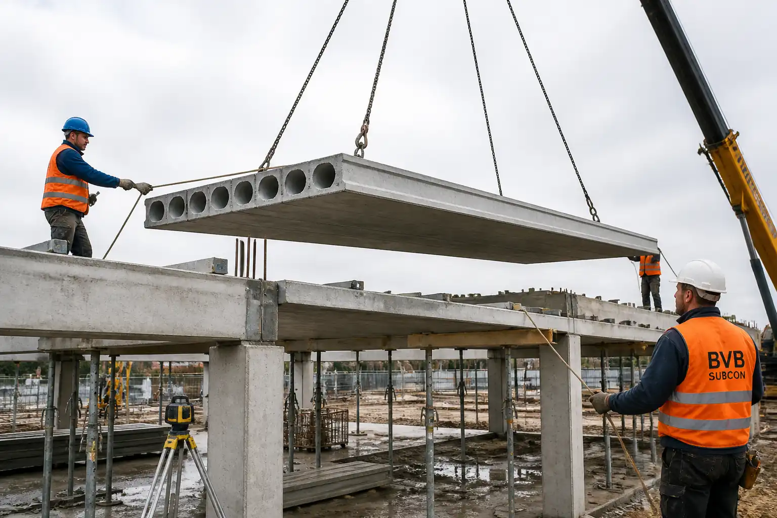
Documents, support levels, bearings, edge angles, propping, lifting, placement, camber/level checks, grout materials, grouting execution, strengths, and final survey.
Typical hold, witness, and review points
Hold: Edge angles, propping, first unit placement, permit to strike. Witness: Bearings, camber checks, grouting.
Typical inspection records
Checklists, torque logs, survey reports, grout test results, permits (load/strike), photos, as-built drawings.
Important approval note
This ITP is an AI-assisted editable starting point, not a pre-approved document. Before use on any project, all inspection activities, hold points, and acceptance criteria must be reviewed and approved by the relevant parties (superintendent, principal contractor, or client representative) in accordance with your contract and project quality plan.
Always verify acceptance criteria against your applicable drawings, specifications, and regulatory requirements. Hold points must be confirmed with the relevant authority before work proceeds past that point.
Inspection and test plan
| Activity | Inspection / Test | Acceptance Criteria | Responsibility | Record |
|---|---|---|---|---|
| Pre-start document review | Approved MS, ITP, TWD, Lift Plan, drawings available on site. | PM / QA-QC | Approved docs list | |
| Support level and set-out survey | Support level ±3 mm over 2 m; grid ±10 mm [Verify]. | Surveyor / QA-QC | Survey report | |
| Bearing preparation | Bearing pads/mortar installed; min. bearing length: masonry ≥ 75 mm; RC/steel ≥ 60 mm [Verify]; ≥90% contact. | Erection Supervisor / QA-QC | Bearing checklist, photos | |
| Edge support angles installation | Torque/pull (sample) | Angle level ±3 mm; anchors spacing per design; torque as data sheet; edge distance satisfied. | QA-QC / Supervisor | Torque log, inspection sheets |
| Temporary propping installed (if required) | Per TWD; stability/bracing confirmed; Permit to Load issued. | TWC / QA-QC | TWC permit | |
| Crane and rigging pre-use | Certificates in date; wind within limit; exclusion zone established. | AP / Crane Operator / QA | Pre-use checklists | |
| First unit placement | Bearing length both ends achieved; orientation correct; alignment to grid ≤ 10 mm. | QA-QC / Supervisor | Inspection record, photos | |
| Bearing length check (100% units) | Measured both ends; meets minimums; contact ≥ 90%. | Supervisor / QA-QC | Checklists | |
| Levels and differential camber | Adjacent level difference ≤ 6 mm over 2 m; differential camber ≤ span/1000 or 10 mm [Verify]. | Surveyor / QA-QC | Camber/level log | |
| Continuity reinforcement in joints | Bar size/spacing/cover per drawings. | QA-QC / Supervisor | Inspection sheet | |
| Grout material approval | COC/Batch cert | Meets ASTM C1107/EN 1504-3 and project requirements. | QA-QC | Approval, certs |
| Grouting execution | Flow test | Flow 20–30 s (ASTM C939) [Verify]; joints filled to refusal; no visible voids/leakage. | Supervisor / QA-QC | Grout log, photos |
| Grout compressive strength | Cubes/cylinders | ≥ 20 MPa before loading [Verify]; ≥ specified 28-day strength. | QA-QC / Lab | Lab reports |
| Permit to strike props (if used) | Strengths achieved; no defects; staged release plan approved. | TWC / QA-QC | Permit to Strike | |
| Final inspection and as-built survey | All tolerances met; records complete; area safe to hand over. | QA-QC / Surveyor | As-built, ITP close-out |
This table is a read-only public reference. Download the PDF or Excel version, or customize this ITP to edit it for your project.
Frequently asked questions
Related method statement
This Inspection and Test Plan is associated with the Method Statement: Laying Prestressed Hollowcore Slabs – Bearings, Edge Angles, Propping, Joint Grouting, and Differential Camber Control method statement, which describes the step-by-step construction sequence, resources, materials, equipment, safety controls, and environmental controls for this activity.
View the Method Statement: Laying Prestressed Hollowcore Slabs – Bearings, Edge Angles, Propping, Joint Grouting, and Differential Camber Control method statement →Continue with related inspection, method statement, article, and checklist resources.