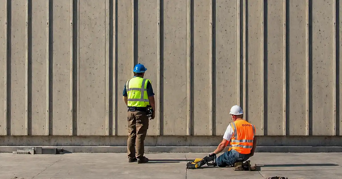
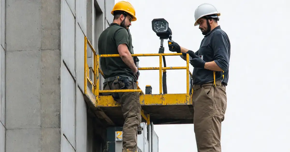
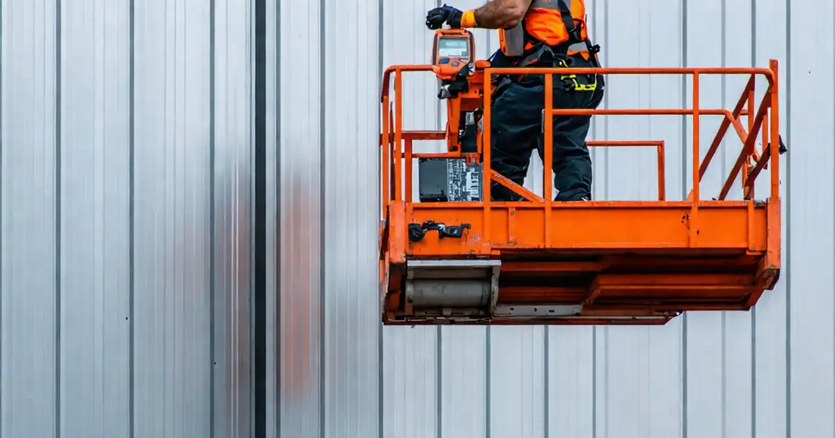
Review Façade Precast Panel Support and Erection Tolerances
Definition: Review façade precast panel support, bearing, and erection tolerances defines field checks for site engineers to verify supports, bearings, and alignment against drawings, ensuring safe installation, accurate joints, and durable performance.
- Verify supports, pads, and anchors match approved drawings and submittals
- Measure plumb, level, joint width, and offsets within stated tolerances
- Document survey readings, photos, lot numbers, and digital approvals
- Interactive, commentable checklist with export and QR code verification
Review façade precast panel support, bearing, and erection tolerances is essential to deliver true, stable cladding. This checklist guides verification of precast cladding tolerances, panel alignment checks, and support-seat readiness before and during erection. You will confirm embed locations, bearing pads, shims, brackets, and connection hardware against approved drawings, then measure plumbness, joint width, and elevation with total station or laser tools. By controlling erection tolerances, you reduce cracked panels, binding connections, leaks, and rework. Scope covers façade precast only—support conditions, minimum bearing, temporary bracing, and final connections—not sealant performance, coating color, or thermal/structural design beyond what is shown on approved documents. All acceptances defer to approved project specifications and authority requirements where stricter. Use this as a field-ready sequence to measure, record evidence, and obtain timely sign-offs so cranes and crews stay productive and safe. Start interactive mode to tick items, add comments, and export your records to PDF/Excel with a QR link.
- Confirm support readiness, bearing pad compliance, and insert locations before lifts, then control alignment during erection. This prevents panel cracking, overstressed connections, and misaligned joints that trigger costly rework and schedule slippage.
- Adopt measurable tolerances for plumbness, elevation, joint width, and offsets using a total station, laser level, gauges, and calibrated torque tools. Capture photos, survey files, batch data, and signatures for traceable quality evidence.
- Interactive online checklist with tick, comment, and export features secured by QR code. Supervisors, erectors, and QA teams can collaborate in real time and archive authenticated records for turnover and future maintenance.
- Standardize acceptance cues: minimum bearing length, shim stack configuration, weld/bolt verification, and bracing installation. Clear acceptance thresholds and evidence requirements reduce ambiguity, speed approvals, and align the field with approved drawings.
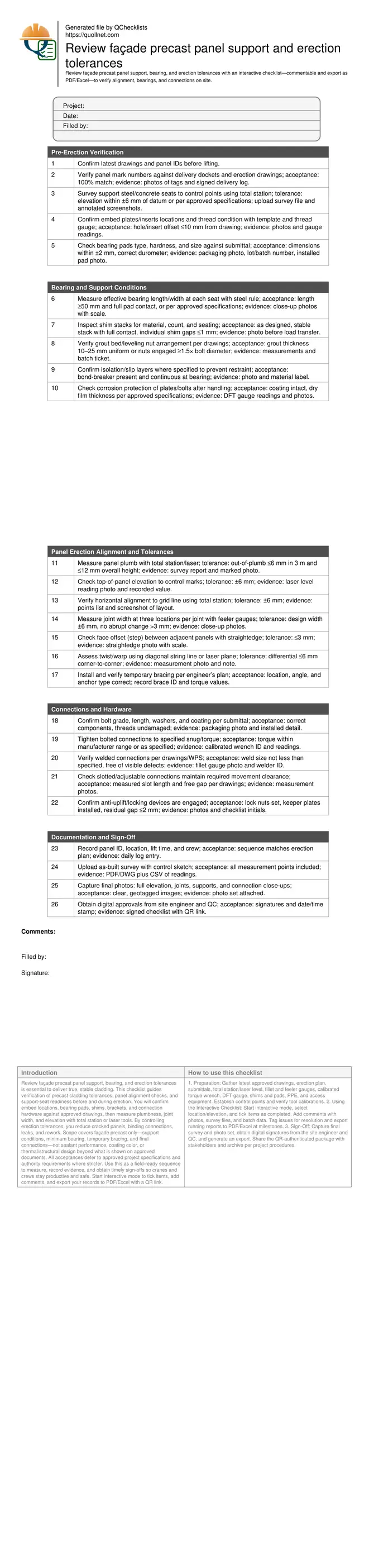
Pre-Erection Verification
Bearing and Support Conditions
Panel Erection Alignment and Tolerances
Connections and Hardware
Documentation and Sign-Off
Set the Stage: Supports, Bearings, and Readiness
Erection quality starts before the first pick. Survey support steel and concrete seats to confirm level and elevation, then verify embed locations and thread condition. Bearing pads and shims must match approved submittals, including size, durometer, and stack configuration, to distribute loads evenly and avoid restraint. Where drawings require bond breakers or isolation, ensure continuous coverage to prevent unintended fixity. Record batch data for grout or pads, and check corrosion protection on plates and bolts after handling. These readiness checks eliminate surprises when the crane is on the clock, reduce panel damage, and set a repeatable baseline for alignment. Acceptance should reference approved project specifications and authority requirements where stricter; when not stated, use practical cues like full pad contact, minimum 50 mm bearing, and tight shim seating. Finish by photographing each bearing, capturing survey points, and labeling positions to speed later review and sign-off.
- Survey seats to ±6 mm elevation before lifting
- Match pads and shims to approved submittals
- Ensure isolation layers where drawings require
- Capture batch numbers, DFT, and condition photos
- Label positions to streamline review and sign-off
Control During Erection: Alignment and Tolerances
With the panel suspended, use a total station or laser to set plumb, elevation, and horizontal position. Work to achievable field tolerances: out-of-plumb within 6 mm in 3 m and 12 mm overall height, joint width within ±6 mm, and face steps not exceeding 3 mm. Check twist using a diagonal string or laser plane to avoid long-term stress and misaligned joints. Temporary braces must be placed as engineered, with anchors and torque recorded. Adjust shims or slotted connections incrementally to achieve final line and level without prying on hardware. Document every reading and adjustment, including photos showing gauges on the surface. These controls minimize cracking, water paths, and future envelope issues, while speeding acceptance.
- Measure plumb, level, grid with total station
- Hold joints to design width ±6 mm
- Limit face step between panels to ≤3 mm
- Record brace installation and torque
- Photograph gauges on the panel face
Lock It In: Connections, Movement, and Evidence
After alignment, install final connections to the drawings. Verify bolt grade, washers, and coating, then tighten to the specified snug or torque, recording calibrated wrench IDs. Inspect weld sizes using fillet gauges and ensure visible quality meets the WPS; schedule NDT where specified. Adjustable or slotted brackets must retain required movement clearance, preventing locked-in restraint from temperature or frame drift. Confirm anti-uplift or keeper devices are engaged. Finish with grout or nut settings as designed, and recheck clearances after load transfer. Compile the evidence: as-built survey, close-ups of supports and joints, photos of gauges, batch tickets, and digital signatures. This documentation proves conformance, simplifies handover, and supports warranty discussions.
- Verify bolt grade, washers, and torque
- Gauge weld size and visible quality
- Maintain movement clearance at slots
- Engage anti-uplift/locking hardware
- As-built survey and signatures attached
How to Use This Interactive Checklist
- Preparation: Gather latest approved drawings, erection plan, submittals, total station/laser level, fillet and feeler gauges, calibrated torque wrench, DFT gauge, shims and pads, PPE, and access equipment. Establish control points and verify tool calibrations.
- Using the Interactive Checklist: Start interactive mode, select location/elevation, and tick items as completed. Add comments with photos, survey files, and batch data. Tag issues for resolution and export running reports to PDF/Excel at milestones.
- Sign-Off: Capture final survey and photo set, obtain digital signatures from the site engineer and QC, and generate an export. Share the QR-authenticated package with stakeholders and archive per project procedures.
Call to Action
- Start Checklist Tick off tasks, leave comments on items or the whole form, and export your completed report to PDF or Excel—with a built-in QR code for authenticity.
- Download Excel - Façade Precast Panel Tolerance Review
- Download PDF - Façade Precast Panel Tolerance Review
- View Image - Façade Precast Panel Tolerance Review
Cite & Embed
“Façade Precast Panel Tolerance Review by Quollnet”
with a link to
this source page.
FAQ
Question: What are typical erection tolerances for precast façade panels?
Question: How much bearing length do I need under a façade precast panel?
Question: When should I measure tolerances during the lift?
Question: What evidence should I keep to prove compliance?
Related Articles
Broader reading and guidance connected to this checklist topic.


Master Construction Project Cashflow With Cashflowpot

High Or Low Concrete Slump: Retest, Hold, Adjust Or Reject?
Related Checklists
Keep the workflow moving with nearby templates chosen from similar checklist content.