Inspect Aluminum Cladding Panel Installation: Alignment & Joint Width
Definition: Inspect aluminum cladding panel installation for alignment and joint width on exterior facades, guiding site engineers, QC inspectors, and installers to verify true lines, consistent joints, and documented acceptance.
- Verify plumb, level, and module lines against approved datums.
- Measure joint gaps with calipers; maintain tolerances for weathering performance.
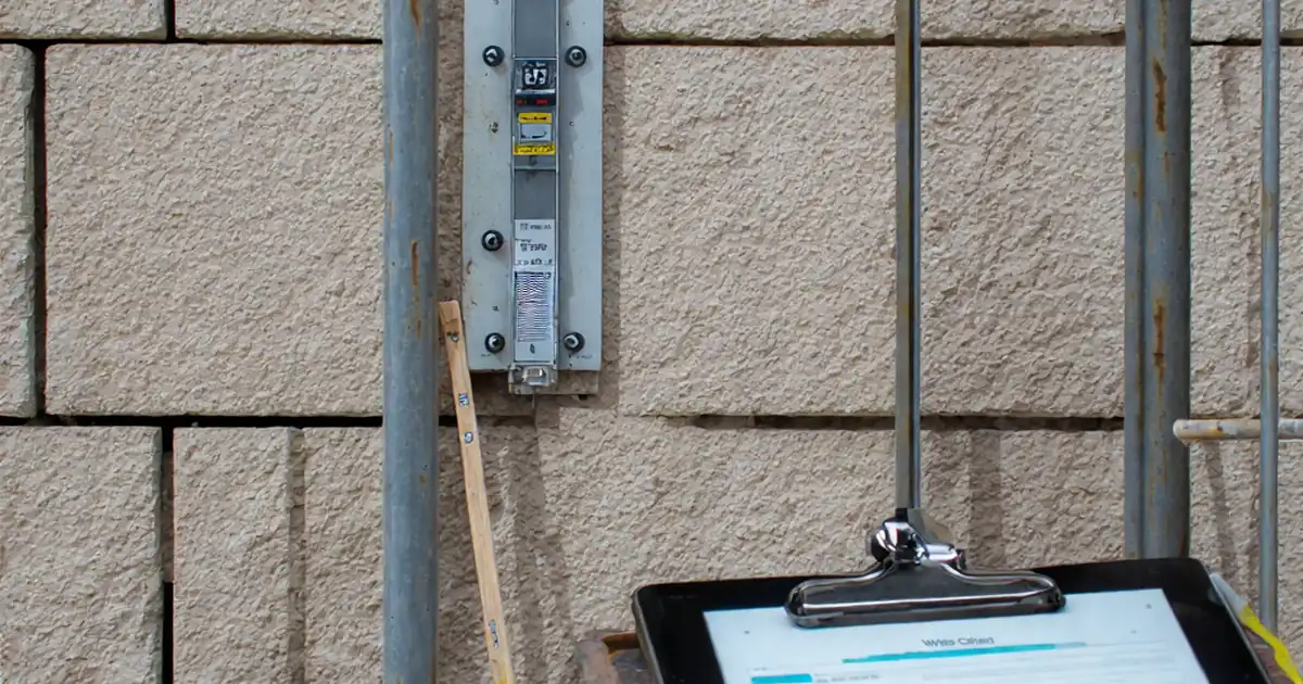
- Capture photo evidence, readings, and batch numbers for traceability.
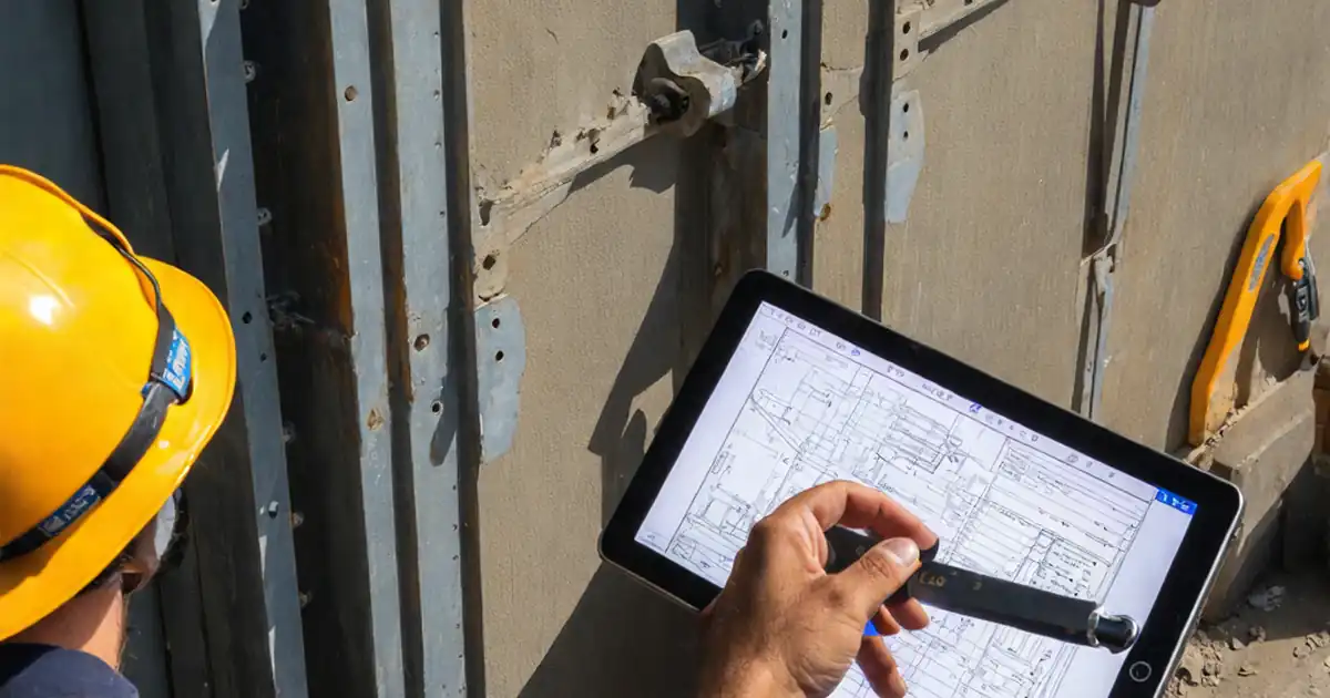
- Interactive, commentable checklist; export reports with QR code verification.
Inspect aluminum cladding panel installation for alignment and joint width is the critical quality gate for a clean, durable façade. This checklist helps you confirm panel alignment, module line continuity, and uniform joint gaps while documenting evidence. You will validate plumb and level against control datums, check joint gap tolerances, and verify that shims, brackets, and fixings do not force panels off line. By focusing on panel alignment and joint uniformity only, it avoids scope creep into unrelated weatherproofing or structural testing. Thorough inspections catch creeping drift across elevations, inconsistent reveals, and joint pinch points that can telegraph through the façade or compromise drainage. Following these steps reduces rework, protects warranties, and ensures the finished appearance matches approved shop drawings and mock-ups. Use this interactive tool to tick off tasks in sequence, add field comments, attach photos and readings, and export your sign-off as PDF/Excel with a QR for authentication.
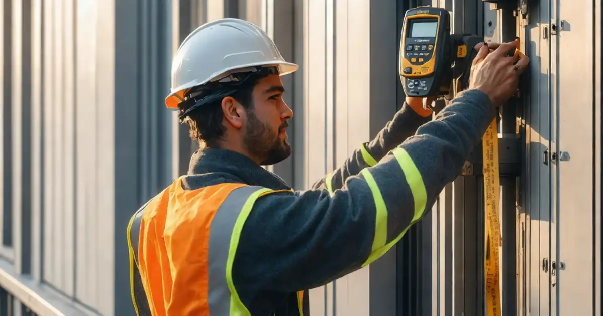
- Confirm precise panel alignment using lasers, levels, and control datums, then document results with geo-tagged photos and readings. The process prevents cumulative drift across elevations and ensures returns, corners, and transitions remain crisp and consistent with approved shop drawings.
- Measure joint widths at multiple locations with digital calipers to hold design reveals, control drainage, and avoid rattling or binding. Joint straightness is checked with a string or laser line, and intrusions from gaskets or backpans are recorded and corrected.
- Interactive online checklist with tick, comment, and export features secured by QR code.
- Record torque values, shim locations, and batch numbers to prove compliance with approved project specifications and authority requirements. Nonconformities are tagged in place, corrected within defined timelines, and rechecked to close out NCRs before final sign-off.
Pre-Inspection Setup
Alignment Verification
Joint Width Verification
Fixings and Supports Related to Alignment
Documentation and Acceptance
Establish Datums and Methods for True Alignment
Accurate panel alignment starts with reliable reference lines. Set horizontal and vertical datums using a total station or rotary laser and label them clearly on the façade. Verify the subframe is within tolerance before you judge the panels, using a 2 m digital level to find bow or twist that could telegraph through. During inspection, extend a laser line across panel edges to check plumb and level, capturing photos that show both the device and the panel edge. Face flushness is best confirmed with a 1.5 m straightedge and a feeler gauge to quantify gaps. At corners and returns, combine a builder’s square with the laser to spot small but visible misalignments. Track your findings on an elevation mark-up to reveal cumulative drift across bays. Keep the focus on alignment only—do not mix in unrelated weatherproofing tests—to maintain clarity and speed.
- Create and label clear horizontal and vertical control datums.
- Confirm subframe plumb/level before judging panel alignment.
- Use lasers and straightedges to quantify deviations.
- Annotate findings on elevation mark-ups for drift control.
Accurate Joint Width Measurement and Control
Uniform joint width drives façade aesthetics and performance. Use a digital caliper to measure vertical joints at the top, mid-height, and bottom, and horizontal joints at left, center, and right. Log each reading and photograph the caliper display near the joint. Check straightness with a string line stretched over 3 m to reveal localized pinch points or bulges. Verify that gaskets, backpans, and baffles do not intrude into open joints, which can collect dirt or obstruct drainage. Spacers and setting blocks must match approved types and spacing so joints don’t creep during service. Around penetrations and outlets, confirm continuity of the specified reveal. Apply tolerances per approved project specifications and authority requirements, typically ±1 mm for joint width and ≤2 mm straightness over 3 m.
- Measure three points per joint orientation with a caliper.
- Photograph readings with the joint and scale visible.
- Check joint straightness with a 3 m string line.
- Verify no gasket or backpan intrudes into joints.
Tolerances, Evidence, and Nonconformity Control
Tolerances protect visual lines and allow for thermal movement. Keep vertical plumb within ≤3 mm over 3 m and level within ≤2 mm per 2 m, unless project documents require otherwise. Record torque on fixings to stop panels shifting after inspection. Note shim stacks and isolators; excessive or uneven shimming may distort joint widths. Combine close-up detail photos with wide-angle elevation shots to show context, and label images with grid references for traceability. When deviations exceed tolerance, tag the panel with a QR label, raise a nonconformity report, and agree corrective actions and deadlines. Reinspect and document closure before final sign-off. Export a consolidated report so stakeholders can review evidence and approvals efficiently.
- Apply tolerances per approved project specifications.
- Record torque, shim thickness, and isolator placement.
- Use QR tags to track and close nonconformities.
- Export a consolidated report for stakeholder review.
How to Use This Alignment & Joint Width Checklist
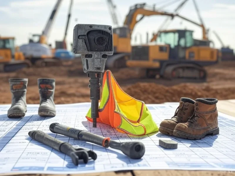
- Preparation: Confirm access equipment, weather conditions, and lighting. Gather laser level, digital caliper, straightedge, string line, torque wrench, PPE, drawings, and calibration certificates.
- Open the checklist and switch to interactive mode. Select the elevation or grid bay you will inspect to auto-stamp location data.
- Tick each step as you proceed. Add comments, attach photos of tools and readings, and enter measurements directly into the specified fields.
- Flag any nonconformity with a QR tag on the panel, assign corrective actions, and set due dates for reinspection.
- Generate a draft report and review completeness. Export as PDF/Excel for stakeholders, including photo logs, readings, and mark-ups.
- Sign-Off: Collect digital signatures, lock the record, and archive with QR authentication to prevent tampering.
Call to Action
- Start Checklist Tick off tasks, leave comments on items or the whole form, and export your completed report to PDF or Excel—with a built-in QR code for authenticity.
- Download Excel - Aluminum Cladding Alignment & Joint Width Inspection
- Download PDF - Aluminum Cladding Alignment & Joint Width Inspection
- View Image - Aluminum Cladding Alignment & Joint Width Inspection
Cite & Embed
“Aluminum Cladding Alignment & Joint Width Inspection by Quollnet”
with a link to
this source page.

FAQ
Question: What alignment tolerance is typically acceptable for aluminum cladding panels?
Question: How should I measure joint width and how many readings are needed?
Question: Which tools are best for verifying alignment accurately on site?
Question: What should I do if joints are wider or narrower than specified?
Related Articles
Broader reading and guidance connected to this checklist topic.


Is It Important To Customize Your Qr Code And How To Do It?
Related Checklists
Keep the workflow moving with nearby templates chosen from similar checklist content.