Inspect Stone Cladding Panel Installation: Line, Level & Joints
Definition: Inspect stone cladding panel installation for line, level, and joint width with field-proven methods for site engineers and inspectors, ensuring aligned facades, consistent joints, and signed evidence within specified tolerances.
- Verify plumb, level, and alignment using laser, straightedge, and gauges.
- Measure vertical and horizontal joint widths to drawing tolerance, ±1 mm.
- Prevent cumulative drift with frequent rechecks from fixed control datums.
- Interactive, commentable checklist with export and QR code verification.
Inspect stone cladding panel installation for line, level, and joint width to assure façade alignment, plumbness, and joint consistency. This checklist focuses on vertical façade panels, using survey control, laser levels, straightedges, and feeler gauges to verify arris line, level coursing, and uniform gaps. It excludes anchor capacity testing and sealant performance; acceptance is gauged strictly by alignment, elevation, and joint-dimension tolerances per approved project specifications and authority requirements. By capturing repeatable measurements at control points, you will prevent cumulative drift, misaligned coursing, and inconsistent joints that cause visual defects, water ingress pathways, and rework. The outcome is a documented, auditable installation that matches shop drawings, maintains architectural intent, and delivers clean, continuous sightlines across bays and floors. Use this interactive checklist to tick each step, add comments and photos at nonconformities, and export your signed records to PDF or Excel. A QR code secures traceability on drawings, bays, and elevations.
- Establish robust survey control and datums before installing or assessing panels. Use total stations or lasers to transfer gridlines and elevations, then lock a repeatable reference for every bay. This prevents early-course errors from compounding into visible misalignment, stepped joints, and uneven coursing across multi-bay façades.
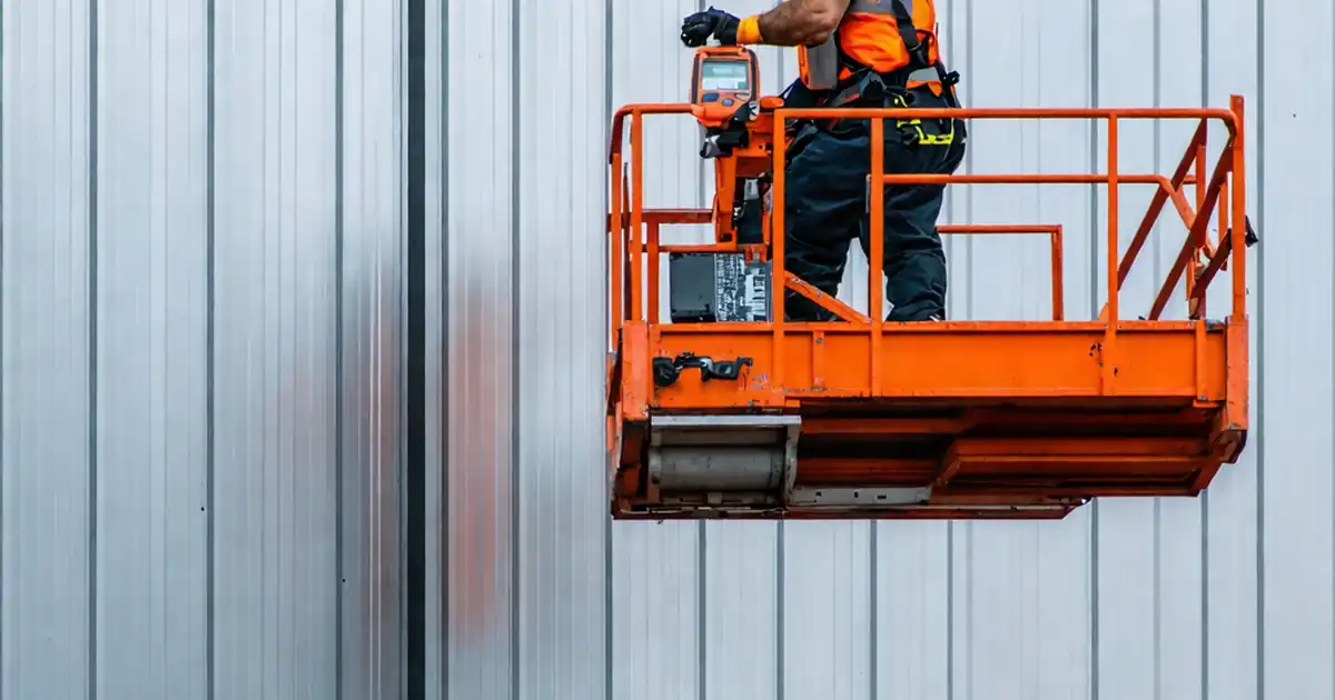
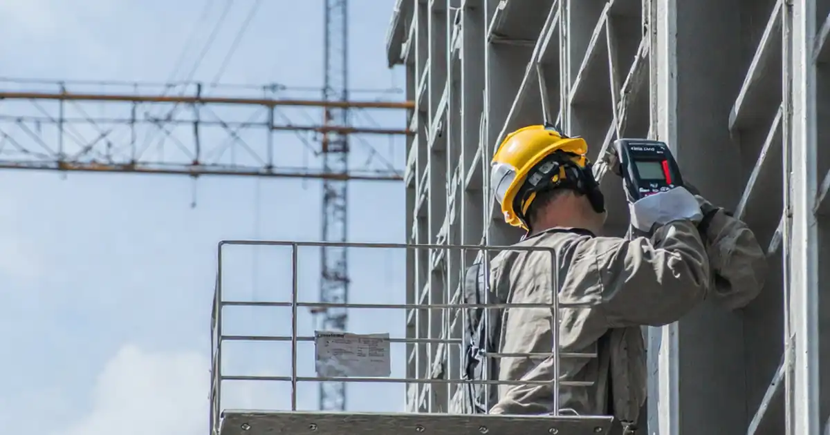
- Apply consistent field methods to verify plumb, level, and line: digital levels for verticality, rotary lasers for elevations, and 1.5–2 m straightedges for flushness. Record actual readings, not pass/fail notes. Capture photos showing tools in place so reviewers can correlate measurements to panel IDs and grid positions.
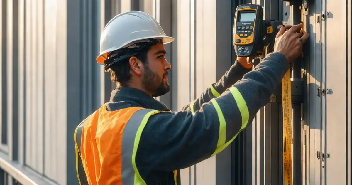
- Control joint width with measurable gauges at three points per joint, horizontally and vertically. Compare against the design width within ±1 mm, and verify joint straightness over 2 m with a laser or straightedge. Managing joint uniformity eliminates visual noise, uneven sealant beads, and moisture traps at transitions.
- Interactive online checklist with tick, comment, and export features secured by QR code.
Pre-Alignment Controls
Line and Plumb Verification
Level and Coursing Checks
Joint Width Measurement
Tolerances and Adjustments
Documentation and Sign-Off
Establish Control for Line, Level, and Joints
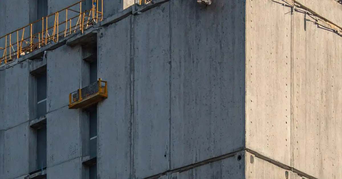
Reliable inspection starts with robust control. Transfer gridlines and elevation datums from the master survey to the façade using a total station or laser. Mark durable witness points at jambs and sills, then set a level base course line before panels rise. Use a 2 m straightedge to check the receiving plane; small deviations can cascade into stepped joints, misaligned arrises, and unacceptable coursing. Lock a repeatable sequence: measure from control, install a limited run, re-verify, then continue. Record actual measurements (not pass/fail) to detect drift early. For complex elevations or long bays, break the façade into inspection lots with clearly tagged control points. Establish a hold point before sealing or pointing so any adjustment remains practical. Always verify that the current shop drawings and detail tolerances are on hand; undocumented assumptions are a frequent root cause of rework. Clear marks, consistent tools, and disciplined intervals produce dependable, defensible inspection results.
- Transfer grid and datum with total station or laser.
- Set base course level line before stacking panels.
- Check receiving plane using a 2 m straightedge.
- Measure, install short run, then re-verify control.
- Define lots and hold points for timely corrections.
Methods to Verify Plumb, Level, and Alignment
Use a digital level or inclinometer to confirm plumb on every panel, recording deviation in millimetres over the panel height and per metre. Check line by projecting a vertical laser at arrises and comparing offsets with feeler gauges at multiple heights. Validate face flushness between adjacent panels with a 1.5–2 m straightedge; light visibility or measurable gaps beyond tolerance reveal lipping or twist. For level coursing, a rotary laser and staff provide quick, auditable readings across the bay. At floor-to-floor transitions, confirm continuity so steps do not telegraph across the elevation. Keep the same calibrated tools on the lot to minimize measurement variance, and photograph instruments in place to connect numbers to physical conditions. When deviations exceed allowable tolerances, adjust shims and brackets immediately, then re-measure and log before/after values with responsible initials.
- Check plumb with a digital level; capture screen readings.
- Compare to a vertical laser line at multiple heights.
- Use 1.5–2 m straightedge to assess flushness.
- Confirm course levels with a rotary laser and staff.
- Re-measure after adjustments; log before/after.
Measuring and Managing Joint Width Consistency
Joint uniformity drives the perceived quality of stone façades. Measure vertical and horizontal joint widths at three positions (ends and middle) using feeler gauges or an adjustable joint gauge. Compare each reading to the design width, typically controlled within ±1 mm unless drawings state otherwise. Check joint straightness over a 2 m length using a laser or straightedge; bowing beyond tolerance signals uneven shimming or panel tilt. At intersections, verify offsets are minimal so sealant beads and arrises appear continuous. Document spacer type and thickness, and remove temporary wedges where specified before sealing. Capture close-up photos with the gauge scale readable, and annotate locations by grid and panel ID. If a pattern or coursing change is present, confirm joint transitions still respect width and alignment criteria. Record any nonconformity, apply corrective actions, and recheck immediately to prevent mismatch propagating along the elevation.
- Take three readings per joint, horizontal and vertical.
- Target design width within ±1 mm unless noted.
- Laser or straightedge checks joint straightness over 2 m.
- Minimize offsets at T and cross intersections.
- Photograph gauges with readable scales and locations.
How to Use This Stone Cladding Inspection Checklist
- Preparation: Assemble total station/laser, digital level, 1.5–2 m straightedge, feeler gauges, calipers, staff, panel ID tags, and PPE. Confirm latest shop drawings, tolerance tables, and inspection lot plan are available.
- Open the checklist, select project, elevation, and lot. Start interactive mode to enable ticking steps, entering measurements, attaching geo-tagged photos, and tagging locations by gridline and level.
- Record measurements: For each item, input numeric readings, variances, and notes. Use the camera tool to capture instruments-in-place and markup photos with arrows or dimensions for clarity.
- Manage issues: If a step fails tolerance, create a nonconformity, assign corrective action, and set a hold point. Re-measure after adjustment and close the issue with before/after evidence.
- Export and share: Generate a commentable report and export as PDF/Excel for review meetings. The QR code links the file to the authenticated record set.
- Sign-Off: Capture digital signatures from installer, site engineer, and QA. Archive the signed report in the project folder and distribute to stakeholders per the communication plan.

Call to Action
- Start Checklist Tick off tasks, leave comments on items or the whole form, and export your completed report to PDF or Excel—with a built-in QR code for authenticity.
- Download Excel - Stone Cladding Line, Level & Joint Inspection
- Download PDF - Stone Cladding Line, Level & Joint Inspection
- View Image - Stone Cladding Line, Level & Joint Inspection
Cite & Embed
“Stone Cladding Line, Level & Joint Inspection by Quollnet”
with a link to
this source page.
FAQ
Question: What tolerances should I use for line, level, and joint width on stone cladding?
Question: How frequently should I take measurements during installation?
Question: Which tools give the most reliable readings on a façade?
Question: How do I document evidence so it stands up to QA and client review?
Related Articles
Broader reading and guidance connected to this checklist topic.

Download Excel Format Snag List


Is It Important To Customize Your Qr Code And How To Do It?

Related Checklists
Keep the workflow moving with nearby templates chosen from similar checklist content.