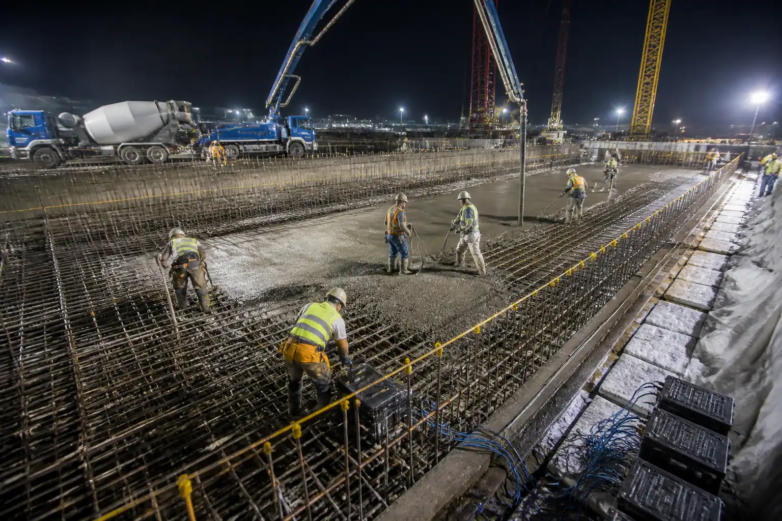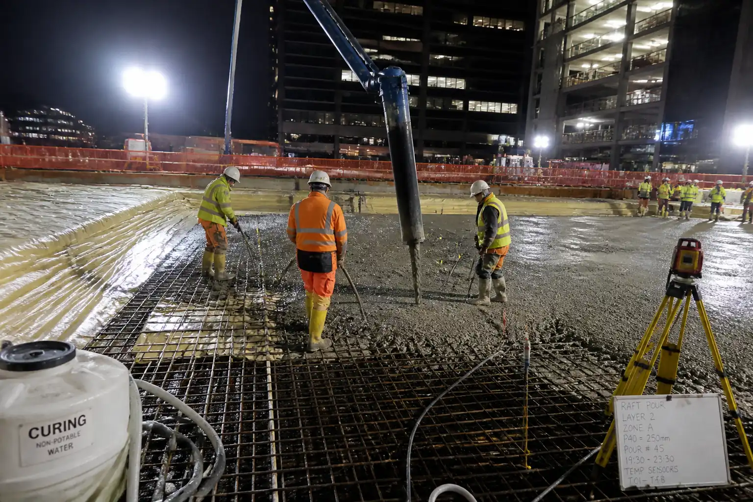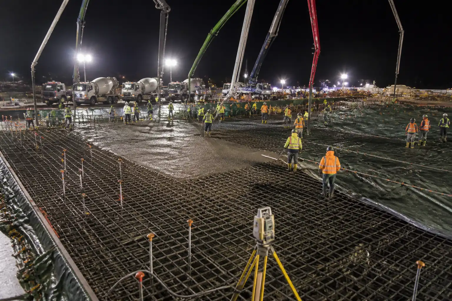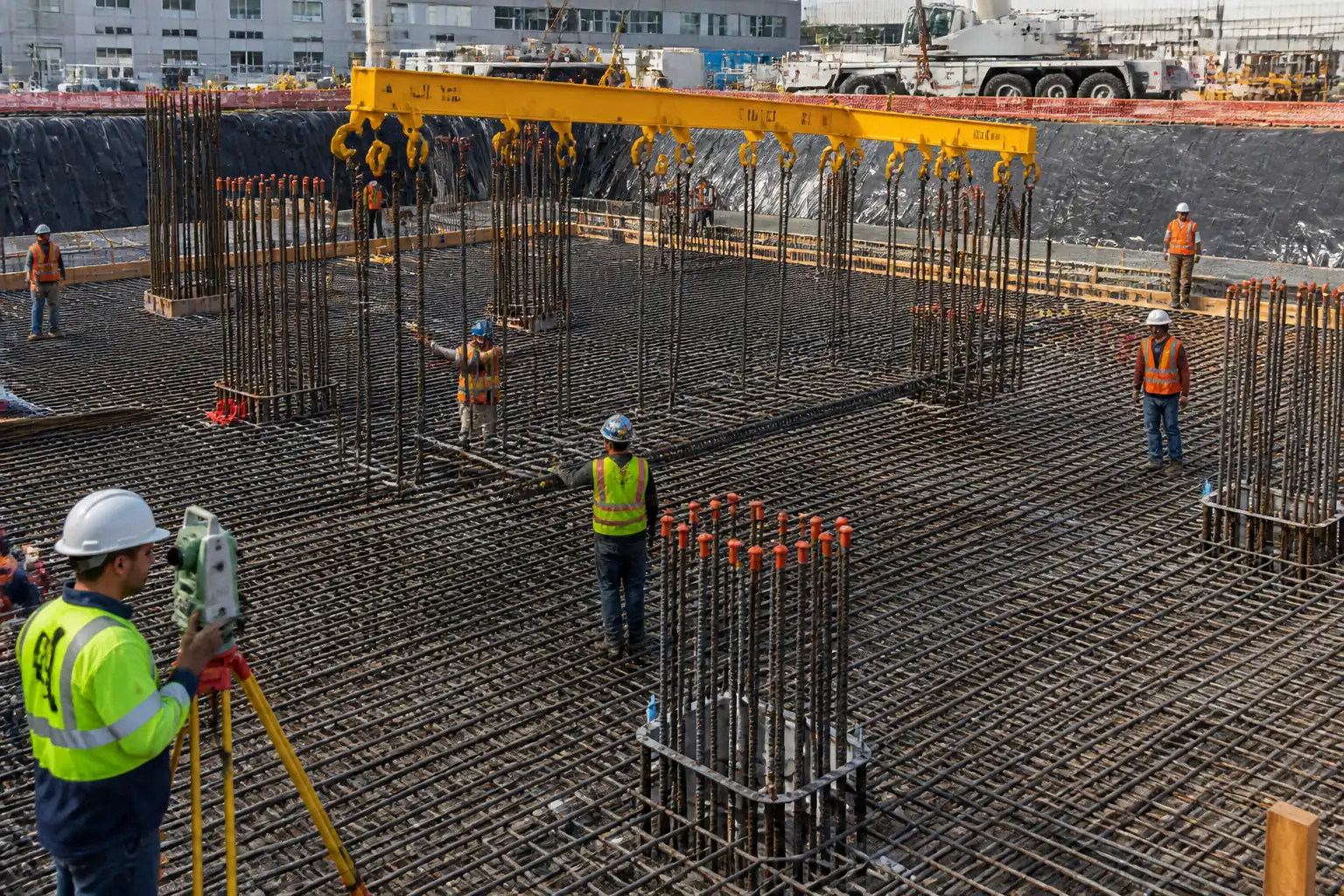
Inspection and Test Plan for Method Statement: Mass Concrete Raft Foundation Pour (Blinding, Waterproofing, Heavy Reinforcement, Thermal Control, Temperature Monitoring, Final QA/QC)
AI-assisted inspection and test plan connected to a method statement, with PDF and Excel export.
More than a static template
Unlike a downloadable Word or PDF template, this ITP is an AI-assisted editable starting point directly connected to its method statement. Every inspection activity, hold point, and acceptance criterion is structured and ready to adapt to your project.
- AI-assisted customization — Tailor inspection activities and acceptance criteria to your specific project scope.
- Linked method statement — This ITP is connected to the corresponding method statement describing the work sequence.
- Multiple export formats — Download as a formatted PDF or editable Excel spreadsheet.
- Editable starting point, not a final document — Review and verify all content against your project specifications and standards before use.
What you can customize
When you save this ITP to your account, every inspection row becomes editable. You can add, remove, or modify:
- Inspection activity — Description of what is being inspected.
- Inspection type — Hold point (H), Witness point (W), Review (R), or Monitor (M).
- Responsibility — Contractor, subcontractor, engineer, or client.
- Frequency — How often the inspection occurs.
- Acceptance criteria — Referenced standard or specification requirement.
- Records — Forms, test reports, or checklists required as evidence.
Why this ITP is used
To verify each critical step meets design and specification requirements, ensuring structural integrity and watertightness.
Who uses this inspection and test plan
Contractor QA/QC, Site Engineers, Testing Agencies, Engineer/Employer’s Representative, and Specialist Subcontractors.
When this ITP is prepared and submitted
From sub-base preparation through final acceptance, with hold and witness points at key milestones such as pre-pour and thermal monitoring.
Who receives or approves this ITP
Engineer/Employer’s Representative for review/approval prior to works.
Inspection scope
Covers blinding, waterproofing, waterstops, reinforcement, embedded items, concrete materials, placement, curing, thermal monitoring, and final documentation.
Typical hold, witness, and review points
Hold: Pre-pour readiness, final acceptance. Witness: Thermal monitoring reviews, fresh concrete testing, waterproofing sign-off.
Typical inspection records
IRs, delivery tickets, field and lab test reports, thermal data, as-built surveys, manufacturer approvals, calibration certificates.
Important approval note
This ITP is an AI-assisted editable starting point, not a pre-approved document. Before use on any project, all inspection activities, hold points, and acceptance criteria must be reviewed and approved by the relevant parties (superintendent, principal contractor, or client representative) in accordance with your contract and project quality plan.
Always verify acceptance criteria against your applicable drawings, specifications, and regulatory requirements. Hold points must be confirmed with the relevant authority before work proceeds past that point.
Inspection and test plan
| Activity | Inspection / Test | Acceptance Criteria | Responsibility | Record |
|---|---|---|---|---|
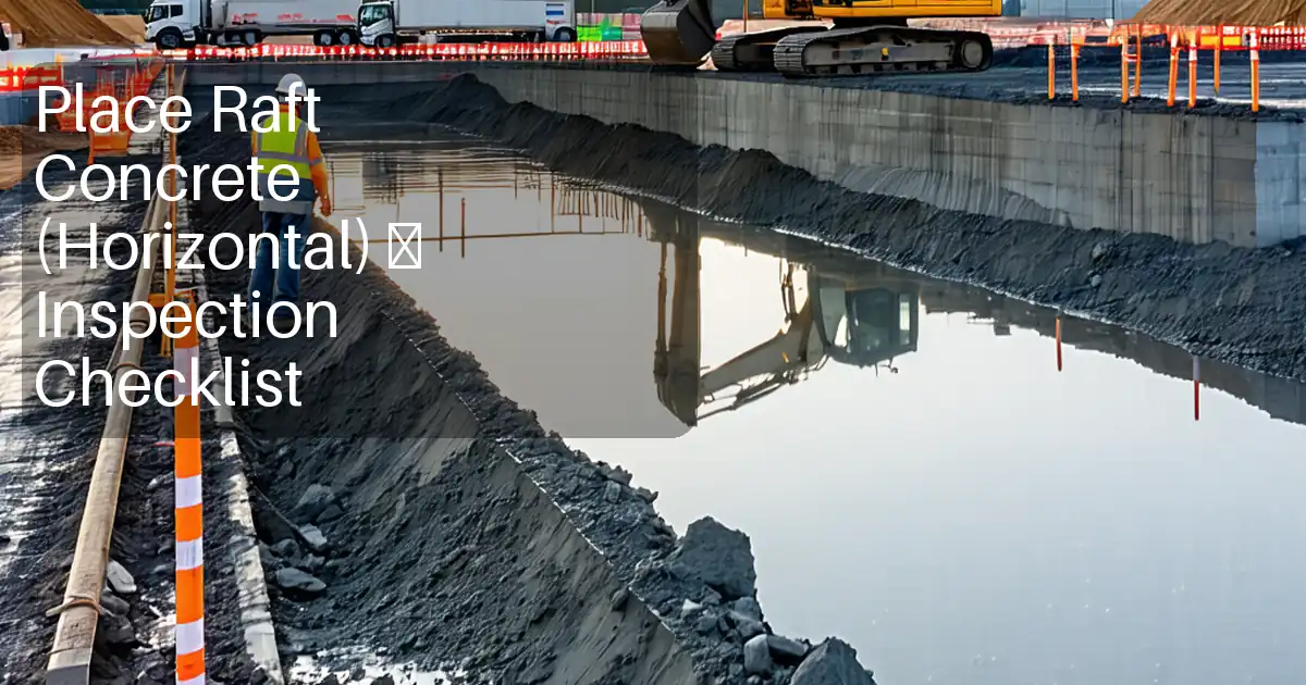
| Sub-base preparation and levels | Survey check; compaction/plate load if specified | Levels within ±10 mm; no soft spots or standing water | Site Engineer / QA/QC | IR, survey report |
| Blinding concrete placement | Random coring or depth probe (if required) | Thickness 50–100 mm; surface smooth and sound [Verify] | QA/QC / Engineer | IR, photos |
| Waterproofing membrane installation | Adhesion check (ASTM D903) if specified; spark/holiday test if applicable | Continuous, defect-free, laps sealed; protection boards installed | Waterproofing Subcontractor / QA/QC / Engineer | IR, manufacturer inspection sheet |
| Waterstop installation | Weld quality check (visual) | Centered in joint; secure; continuous with sound welds | QA/QC / Engineer | IR, photos |
| Rebar material verification | Random bar size/grade check | Compliance with BS 4449/A615; correct grades and diameters | QA/QC | Certificates, IR |
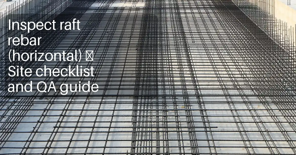
| Reinforcement installation and cover | Cover gauge readings | Cover within −0/+10 mm; spacing per drawings; laps/couplers per design | QA/QC / Engineer | IR, cover checklists |
| Embedded items/MEP coordination | Survey spot checks | Within ±10 mm plan; ±5 mm elevation [Verify] | Site Engineer / QA/QC | IR, as-built survey |
| Formwork/edge shutter | Visual and measurement | Line/level ±5 mm; grout-tight; adequate bracing | QA/QC / Engineer | IR, checklist |
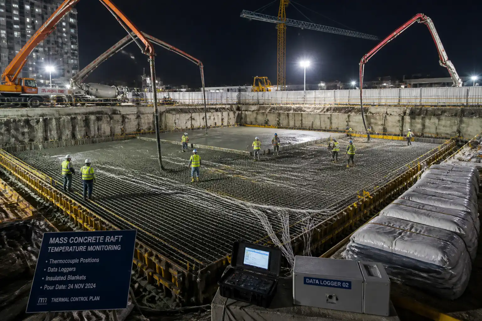
| Thermocouple installation and logger commissioning | Channel verification | All channels operational; baseline recorded pre-pour | QA/QC | Instrumentation report |
| Pre-pour hold point | Checklist sign-off | All preceding inspections closed; logistics and HSE ready | Engineer / Employer / Contractor | Signed hold point release |
| Concrete delivery acceptance | Check batch time, mix ID, water additions | Compliant with approved mix; time limit not exceeded [e.g., 90 min] [Verify] | QA/QC | Tickets |
| Fresh concrete testing | Slump (C143), Temp (C1064), Air (C231 if specified), Unit weight (C138) per frequency (1/50 m³ or 1/10 trucks min) [Verify] | Within approved ranges; reject non-conforming loads | QC Technician / Testing Agency | Field test reports |
| Specimen making and curing | ASTM C31 / EN 12390-2 | Specimens properly made and cured | QC Technician / Testing Agency | Specimen log |
| Placement/compaction monitoring | Visual; vibration technique checks | No cold joints; proper vibration; lift heights 450–600 mm | Site Engineer / QA/QC | Supervisor log |
| Curing commencement | Visual | Curing started within specified time; full surface coverage | Site Engineer / QA/QC | Curing log |
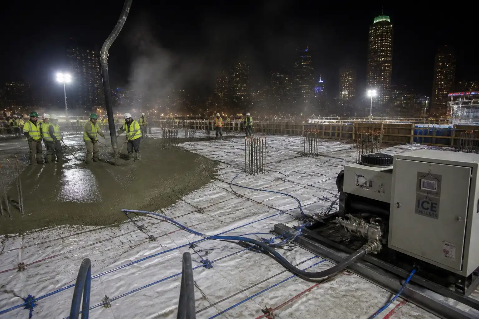
| Temperature monitoring and thermal control | Logger downloads and trend analysis | Peak core ≤65–70°C and ΔT surface-core ≤20°C [Verify per project]; cooling rate ≤2–3°C/h [Verify] | QA/QC Engineer | Temperature reports |
| Compressive strength testing | ASTM C39 / EN 12390-3 at 7/28 days | ≥ specified f'c at 28 days [Verify] | Testing Agency | Lab reports |
| Defect inspection and repairs | NDT if directed | No unacceptable defects; repairs approved | QA/QC / Engineer | Inspection and repair records |
| Final documentation and acceptance | N/A | All ITP points closed; warranties and certificates submitted; Engineer acceptance | Project Manager / QA/QC / Engineer | Final acceptance certificate |
This table is a read-only public reference. Download the PDF or Excel version, or customize this ITP to edit it for your project.
Frequently asked questions
Related method statement
This Inspection and Test Plan is associated with the Method Statement: Mass Concrete Raft Foundation Pour (Blinding, Waterproofing, Heavy Reinforcement, Thermal Control, Temperature Monitoring, Final QA/QC) method statement, which describes the step-by-step construction sequence, resources, materials, equipment, safety controls, and environmental controls for this activity.
View the Method Statement: Mass Concrete Raft Foundation Pour (Blinding, Waterproofing, Heavy Reinforcement, Thermal Control, Temperature Monitoring, Final QA/QC) method statement →Continue with related inspection, method statement, article, and checklist resources.