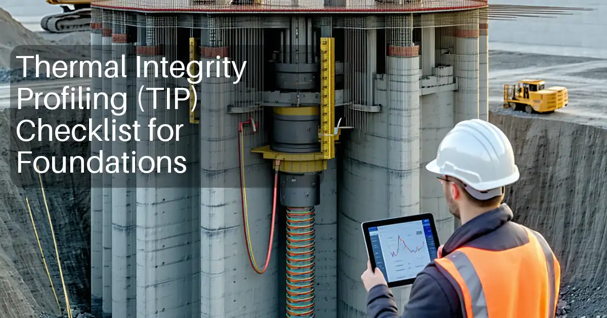
Method Statement: Thermal Cracking Control for Mass Concrete (Pre-cooling, Post-cooling Pipes, Insulation, and Temperature Monitoring) – Method Statement
AI-assisted method statement with matching ITP, PDF download, and Excel export.
More than a static template
Unlike a downloadable Word or PDF template, this method statement is an AI-assisted editable starting point connected directly to a matching Inspection and Test Plan. Every section is structured, project-adaptable, and ready to export.
- AI-assisted drafting — Customize every section with AI for your specific project scope.
- Linked ITP — A matching inspection and test plan is generated alongside the method statement.
- Multiple export formats — Download as a formatted PDF or editable Excel spreadsheet.
- Editable starting point, not a final document — Review, verify, and adjust all content against your project requirements before use.
Static template vs. Quollnet workflow
| Feature | Static template | Quollnet |
|---|---|---|
| Project-specific content | Manual fill-in required | AI-assisted customization |
| Linked ITP | Separate document, no link | Matching ITP included |
| Export formats | Usually PDF only | PDF and Excel |
| Structured sections | Free-form layout | 13 standardized sections |
| Saved to your account | Local file only | Cloud-saved, reusable |
| Content accuracy | You verify everything | AI-assisted, you still verify |
| Cost | Often free but time-intensive | Free to customize and download |
What you can customize
When you save this method statement to your account, every section becomes editable. The following 13 sections are included:
- Scope — Defines the activity and its boundaries.
- References — Standards, specifications, and drawings.
- Responsibilities — Roles and accountabilities.
- Resources — Labour, plant, and equipment summary.
- Materials — Materials and compliance requirements.
- Equipment — Tools and equipment details.
- Prerequisites — Hold points and pre-conditions.
- Method sequence — Step-by-step construction sequence.
- Safety controls — HSE risk controls and PPE.
- Environmental controls — Environmental mitigation measures.
- QA/QC — Quality inspection and test requirements.
- ITP — Inspection and Test Plan table (has its own page).
- Attachments — Referenced drawings and documentation.
Why this method statement is used
This method statement is used to define and communicate the approved procedure for carrying out method statement: thermal cracking control for mass concrete (pre-cooling, post-cooling pipes, insulation, and temperature monitoring) on site. It ensures the work is planned in advance, the correct resources and controls are in place, and all personnel understand responsibilities, sequence, quality requirements, and safety controls before work begins. It aligns site execution with the documented scope and acceptance expectations.
Who uses this method statement
This method statement is used by contractors, site supervisors, project engineers, QA/QC engineers, HSE officers, consultants, and client representatives. It serves as a shared reference for planning, execution, supervision, inspection, and approval of the activity on site.
When it is prepared and submitted
The method statement is prepared before the work activity starts and submitted as part of the pre-construction documentation package for review and approval.
Who reviews or approves it
The method statement is usually submitted to the client representative, consultant, resident engineer, or project management consultant for review and approval before the work commences.
Important approval note
This method statement is an AI-assisted editable starting point, not a pre-approved document. Before use on any project, all content must be reviewed and approved by the relevant parties (superintendent, principal contractor, or client representative) in accordance with your contract and project quality plan.
For example: if your specification requires a departure from a referenced standard, that departure must be documented and approved separately — this method statement will not capture that automatically. Always verify against your applicable drawings, specifications, and regulatory requirements.
Method statement content
Scope
Purpose
Define procedures and controls to prevent early-age thermal cracking in mass concrete through design verification, pre-cooling, post-cooling pipe systems, curing/insulation, and continuous temperature monitoring with hold points.
Applies To
- Raft foundations, thick walls, core walls, transfer beams/blocks, pile caps, dams, abutments, and other mass concrete elements where section thickness typically ≥ 0.8 m [Verify per project specifications].
Objectives
- Limit peak internal temperature and temperature differential (core-to-surface and between adjacent lifts) to within specified limits.
- Achieve controlled temperature rise/fall rates and maintain concrete durability and performance.
- Provide verifiable records of thermal performance and conformity.
Key Acceptance Targets [Verify per project specifications]
- Maximum fresh concrete placing temperature (Tplace): Target ≤ 18°C; Absolute limit ≤ 21°C.
- Maximum core temperature (Tcore,max): Typically ≤ 70°C (Portland cement systems to reduce DEF risk).
- Maximum temperature differential (ΔT = Tcore − Tsurface): Typically ≤ 20°C.
- Maximum cooling/temperature change rate: ≤ 1.0°C per hour; surface cooling rate ≤ 2.0°C per hour.
- Insulation removal when ΔT ≤ 10°C and decreasing, element temperature within 5°C of ambient or per approved model.
References
| Document Type | Reference / Number | Revision | Notes |
|---|---|---|---|
| ACI 207.1R - Guide to Mass Concrete | Thermal behavior, temperature control, cooling pipe guidance. | ||
| ACI 301 - Specifications for Structural Concrete | General requirements and quality control. | ||
| ACI 305R - Hot Weather Concreting | Pre-cooling and placement temperature control. | ||
| ACI 306R - Cold Weather Concreting | Insulation, controlled cooling, minimum temperatures. | ||
| ACI 308R - Guide to External Curing of Concrete | Curing principles and practices. | ||
| BS EN 206 / BS 8500 | Concrete specification and production controls (Europe/UK). | ||
| BS EN 13670 - Execution of Concrete Structures | Execution, curing, and control tolerances. | ||
| Eurocode 2 (EN 1992) | Thermal actions and cracking control principles. | ||
| ASTM C94/C94M - Ready-Mixed Concrete | Production, delivery, temperature measurement at discharge. | ||
| ASTM C1064/C1064M - Temperature of Fresh Concrete | Fresh concrete temperature test method. | ||
| ASTM C1074 - Maturity Method | Optional strength/temperature-time estimation for early-age control. | ||
| CIRIA C660 (or latest) - Early-age thermal crack control in concrete | UK guidance on thermal analysis and detailing. | ||
| ISO 9001 / ISO 14001 / ISO 45001 | Quality, environmental, and occupational health & safety management systems. |
Responsibilities
| Role | Responsibility | Name / Party |
|---|---|---|
| Project Manager | Overall delivery per contract, resources, approvals, and coordination with stakeholders. | Main Contractor |
| QA/QC Manager | Prepare thermal control plan, thermal model review, ITP, hold points, and records. | Main Contractor |
| Concrete/Thermal Control Engineer | Design/verify cooling pipe layout, sensor plan, acceptance limits, and monitoring protocol. | Main Contractor |
| Site Engineer / Construction Manager | Site execution of installation, pour sequencing, insulation, and coordination of plant. | Main Contractor |
| MEP Supervisor (Cooling System) | Install and commission cooling pipes, manifolds, pumps, chillers, and ensure leak/pressure testing. | Main Contractor/Subcontractor |
| Instrumentation Technician | Install thermocouples, data loggers, telemetry; calibrate and maintain monitoring system. | Main Contractor/Subcontractor |
| Engineer/Consultant Representative | Review and approve thermal control plan, ITP hold points, and any change requests. | Engineer |
| HSE Manager | Risk assessments, permits, supervision of HSE controls for cooling plants, handling ice/LN2, and work around formwork. | Main Contractor |
Resources
| Resource Type | Description | Quantity | Remarks |
|---|---|---|---|
| Personnel | 6–8 [Verify] | ||
| Personnel | 12–20 per pour [Verify] | ||
| Personnel | 6–10 [Verify] |
Materials
| Material | Specification / Grade | Quantity | Remarks |
|---|---|---|---|
| Cementitious binders and SCMs | BS EN 197-1 / ASTM C150, C618, C989 [Verify] | Per approved mix design | |
| Chilled water and ice | ACI 305R, ASTM C94 | As per batch water ratio | |
| Insulation materials | Contract spec / ACI 306R guidance | As per surface area | |
| Post-cooling pipes and manifolds | Pressure rating ≥ 6 bar; ISO/EN pipe standards [Verify] | As per layout | |
| Temperature sensors and data systems | Accuracy ±0.5°C or better; IP65+ enclosures [Verify] | Per sensor plan | |
| Cooling loop fluid | Potable or treated water preferred [Verify] | As required |
Equipment
| Equipment | Capacity / Type | Quantity | Inspection Required |
|---|---|---|---|
| Water chillers/heat exchangers | Flow 1–3 L/min per pipe circuit | 1–3 units [Verify] | |
| Pressure test pump and gauges | 2 | ||
| Flow meters and balancing valves | As required | ||
| Concrete placing equipment | As per pour plan | ||
| Instrumentation and telemetry | As per sensor count | ||
| Pre-cooling support equipment | As required |
Prerequisites
- Approved thermal control plan including: target/limit values (Tplace, Tcore,max, ΔT, cooling rates), pour schedule, lift thickness, model outputs (peak and gradients), and contingency actions.
- Approved concrete mix design(s) with documented adiabatic temperature rise or equivalent thermal data.
- Reviewed and approved drawings for: cooling pipe layout, manifolds, insulation plan, sensor locations and IDs, cable routes, logger positions.
- ITP with defined hold/witness points and acceptance criteria; checklists prepared.
- Calibration certificates for thermocouples, loggers, and gauges (valid, traceable); pre-pour functional test reports.
- Commissioned chiller system, power supplies with backup (generator/UPS), and verified flows/pressures.
- Weather forecast reviewed (48–72 hours) and pour timing optimized [Verify per project plan].
- HSE risk assessments, method statements of interfacing trades, permits (hot work, lifting, electrical, confined space if applicable) [Verify per project HSE plan and local regulations].
- Mock-up or pilot pour executed where specified; lessons learned incorporated.
- Materials availability confirmed (ice/chilled water capacity, insulation stock), logistics and access routes cleared.
Method Sequence
| Step | Activity | Description | Responsibility | Inspection / Hold Point |
|---|---|---|---|---|
| 1 | Thermal design verification | Review design thermal analysis; confirm Tcore,max, ΔT limits, expected peak times, lift thickness, and cooling demand. Update with SCM content and cement heat data. | Concrete/Thermal Control Engineer | Hold Point H1: Approve thermal control plan and acceptance limits before any installation. |
| 2 | Cooling pipe system design and procurement | Develop layout: pipe OD 25–32 mm, spacing 1.5–3.0 m horizontally/vertically, standoff ~75–100 mm from rebar, embed at 1/3 to 1/2 depth from surface for each layer; provide manifolds and isolation valves. | MEP Supervisor with Thermal Control Engineer | Witness |
| 3 | Install and pressure test cooling pipes | Fix pipes to reinforcement using non-abrasive ties; protect against movement; label circuits; hydrotest prior to concrete: 1.5× operating pressure (typ. test 3 bar) for 30 min—no pressure drop > 0.1 bar and no leakage. | MEP Supervisor | Hold Point H2: Pressure test acceptance prior to pour. |
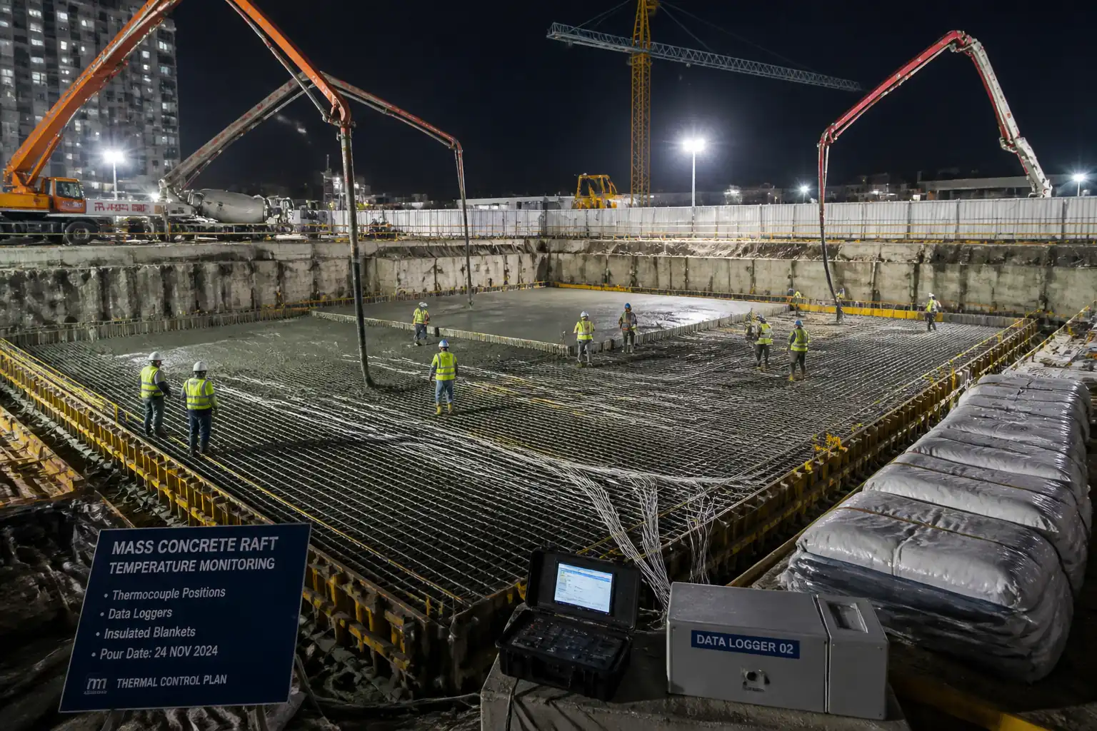
| 4 | Sensor installation and commissioning | Install thermocouples at core, mid-depth, 50–75 mm below surface, and at interfaces/lifts; minimum 1 sensor per 10–20 m³ with not less than 8 per large pour [Verify]. Tag IDs, route in conduits, connect to loggers; function test and ice-point check (0°C). | Instrumentation Technician | Hold Point H3: Sensor map and calibration approval before pour. |
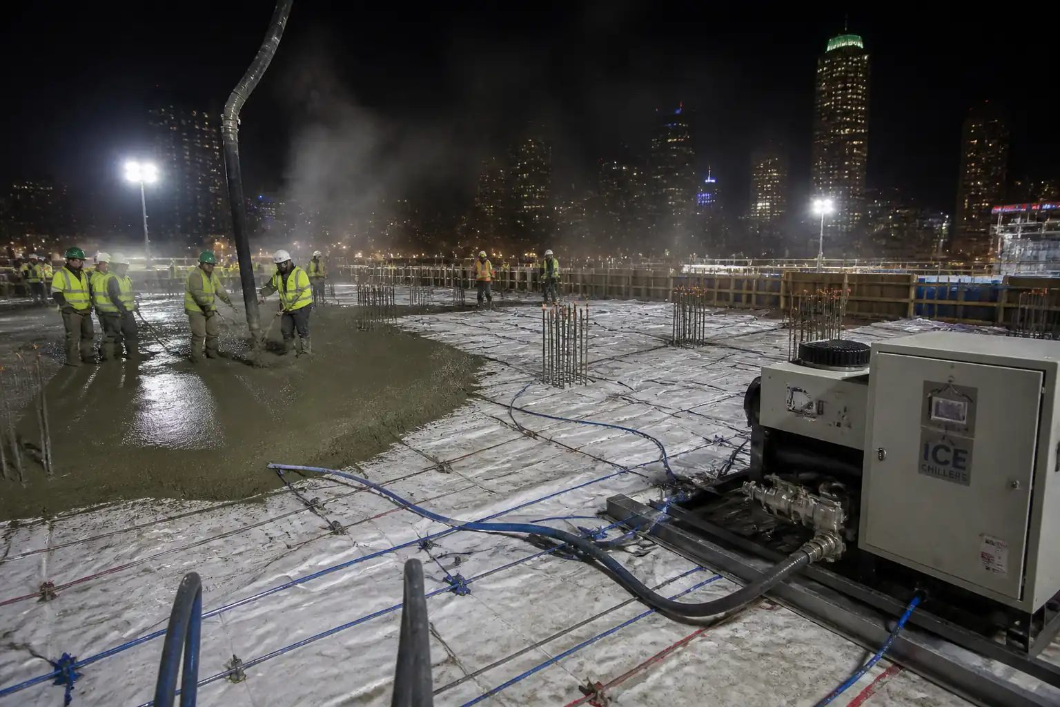
| 5 | Pre-cooling arrangements at batch plant | Set up chilled water/ice dosing; target batch water 2–7°C; replace up to 80–100% of water with ice as required; shade aggregates; pre-chill aggregate spray; verify Tplace control. | Ready-Mix Supplier / QA-QC | Witness |
| 6 | Pre-pour briefing and permits | Conduct pre-pour meeting: sequence, rates, backup plant, HSE, ITP points, contingency. Issue permits (lifting, electrical, confined space if applicable). | Construction Manager / HSE Manager | Witness |
| 7 | Concrete receipt and verification | At site, verify slump/flow, air, temperature, delivery time; reject out-of-spec loads; sequence trucks to maintain continuous placement. | QA/QC Inspector | Witness |
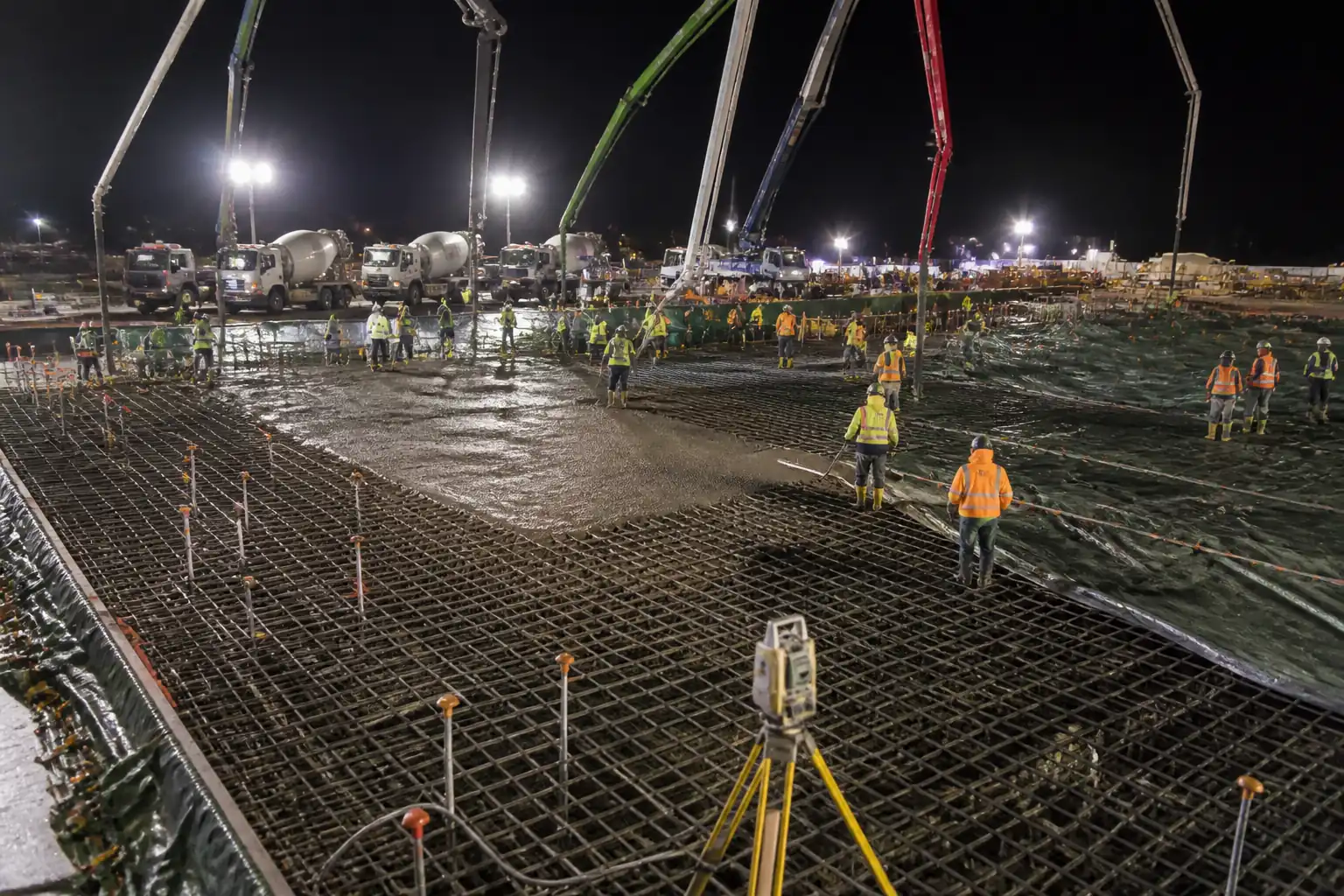
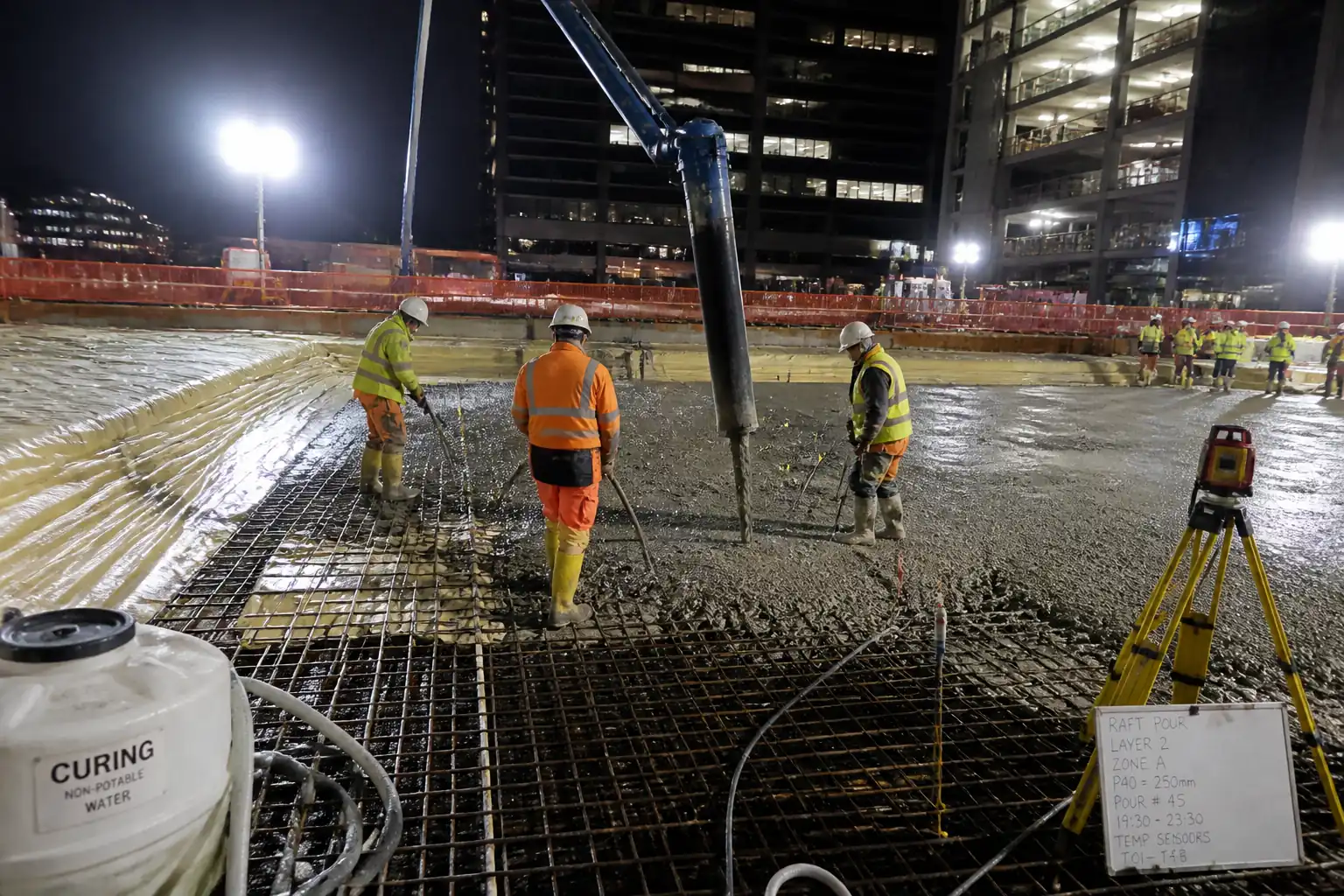
| 8 | Placement and compaction | Place in lifts 0.3–0.6 m; avoid cold joints; use internal vibrators (12–20 s per insertion, spacing 8–10× head diameter). Control pour rate to thermal plan. | Site Engineer / Foreman | Surveillance |
| 9 | Initial curing and insulation | As finishing permits, apply curing compound or moist cure; immediately install insulation/blankets per plan to prevent rapid surface cooling. Seal edges and penetrations. | Site Engineer | Witness |
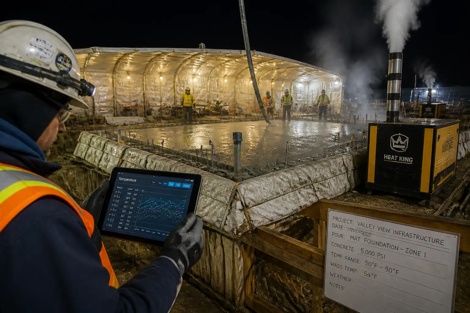
| 10 | Start post-cooling | Commence circulation once hydration rise begins or as modeled (typically within 2–6 h after placement). Start with tempered water (8–12°C), ramp to 2–7°C. Balance flows 1–3 L/min per circuit. Maintain continuous operation with N+1 redundancy. | MEP Supervisor / Thermal Control Engineer | Hold Point H4: Authorization to start cooling. |
| 11 | Continuous temperature monitoring | Log temperature at ≤15 min intervals; review alarms at thresholds: Warning when ΔT ≥ 16°C, Action at ΔT ≥ 18°C, Limit at ΔT = 20°C [Verify]. Adjust cooling/insulation per response plan. | Thermal Control Engineer / QA-QC | Witness |
| 12 | Cooling ramp-down and stabilization | When peak has passed and ΔT ≤ 12°C and trending down, incrementally increase supply temperature or reduce flow over 24–72 h to avoid rebound. Maintain surface insulation until ΔT ≤ 10°C and element within 5°C of ambient. | Thermal Control Engineer | Witness |
| 13 | Terminate cooling and remove insulation/formwork | Hold review of last 24–48 h data. Stop cooling, isolate/flush circuits, cap pipe ends or prepare for reuse. Remove insulation when criteria met. Do not expose surface to sudden drafts or rain shock—use temporary covers if required. | Construction Manager / MEP Supervisor | Hold Point H5: Authorization to demobilize cooling/insulation. |
| 14 | Post-pour testing and close-out | Cast and test cylinders/cubes; review maturity (if used). Compile as-builts (sensor/pipe maps), data exports (native + CSV/PDF), and lessons learned. | QA/QC Manager | Witness |
Health, Safety, and Environment (HSE) - Safety Controls
Task-specific hazards and controls
- Hazard: Pressurized cooling circuits/pumps
- Consequence: Hose/pipe burst, impact injuries, fluid injection
- Engineering/Procedural Control: Hydrotest before use; pressure relief valves; secure hose whip-checks; protect manifolds; operate within set pressure; lockable isolations
- Required PPE: Safety glasses/face shield, gloves, long sleeves, safety boots
- Collective Measures: Barriers and signage around manifolds; exclusion zones
-
Inspection/Permit/Supervision: Pre-use inspection checklist; hold point H2 sign-off; competent MEP supervision
-
Hazard: Cold exposure/thermal burns (ice, chilled water, LN2 if used)
- Consequence: Frostbite, skin/eye injury, asphyxiation risk with LN2
- Engineering/Procedural Control: Prefer chilled water/ice; LN2 only with specific method and ventilation plan; insulated lines; decant tools; no bare-hand handling of ice
- PPE: Cryogenic-rated gloves for LN2, thermal gloves for ice, goggles/face shield, aprons
- Collective Measures: Ventilation; oxygen monitor if LN2 used indoors
-
Inspection/Permit/Supervision: Special permit for cryogen use; HSE approval [Verify per project HSE plan and local regulations]
-
Hazard: Electrical hazards (chillers, pumps, data loggers)
- Consequence: Shock, arc flash, fire
- Engineering/Procedural Control: RCD/GFCI protection; IP-rated enclosures; verified earthing; cable management; lockout/tagout for maintenance
- PPE: Dielectric gloves when testing, safety footwear
- Collective Measures: Temporary power boards with overload protection; cord covers/ramps
-
Inspection/Permit/Supervision: Electrical permit; weekly PAT testing records; electrician supervision
-
Hazard: Trips/falls on rebar/formwork and sensor cables
- Consequence: Sprains, falls from height
- Engineering/Procedural Control: Cable routing in conduits; graded access ways; fall protection at edges; housekeeping
- PPE: Helmets, gloves, boots, fall arrest where required
- Collective Measures: Edge protection/guardrails; designated walkways
-
Inspection/Permit/Supervision: Working-at-height permit; daily supervisor inspection
-
Hazard: Concrete chemical burns and silica dust (cutting/finishing)
- Consequence: Dermatitis, eye injury, respiratory irritation
- Engineering/Procedural Control: Wet methods for cutting; avoid dry grinding; wash stations; skin protection protocols
- PPE: Alkali-resistant gloves, goggles, long sleeves; FFP2/3 respirator if dust risk
- Collective Measures: Dust suppression units; eyewash stations
-
Inspection/Permit/Supervision: COSHH/SDS review; HSE audits
-
Hazard: Lifting operations (insulation packs, manifolds)
- Consequence: Crush injuries, dropped objects
- Engineering/Procedural Control: Rated slings; taglines; no standing under loads; lift plan and appointed person
- PPE: Helmets with chin straps, gloves, boots, Hi-Vis
- Collective Measures: Exclusion zones; spotters
-
Inspection/Permit/Supervision: Lifting permit; crane/hoist inspections
-
Hazard: Heat stress or cold stress for crews (night pours, winter conditions)
- Consequence: Fatigue, hypothermia/heat exhaustion
- Engineering/Procedural Control: Work/rest cycles; hydration/warm areas; scheduling to avoid extremes
- PPE: Weather-appropriate clothing, hydration packs
- Collective Measures: Shaded/rest shelters or heated tents
- Inspection/Permit/Supervision: HSE monitoring; first-aid readiness
[All measures to be verified per project HSE plan and local regulations.]
Environmental Controls
- Cooling water management
- Use closed-loop systems to avoid discharge. If discharge is necessary, cool to within local limits and maintain pH 6–9; no chlorinated or glycol-laden fluids to storm drains [Verify per permits].
-
Secondary containment (bunds) for chillers and pumps; drip trays at manifolds.
-
Noise and energy
-
Locate chillers away from receptors; install acoustic barriers if required; operate in economy modes off-peak when feasible; maintain equipment for efficiency.
-
Material stewardship
-
Prefer SCMs to reduce clinker-related CO2. Store insulation to avoid damage and reuse where possible.
-
Concrete washout and fines
-
Dedicated washout with liners; collect and dispose via licensed contractor; prevent runoff to watercourses.
-
Waste and spill response
-
Segregate packaging waste; keep spill kits at manifolds and power skids; report and log incidents.
-
Temperature monitoring equipment E-waste
- At project end, collect batteries/data loggers for proper recycling per manufacturer guidance.
Quality Assurance and Quality Control
QA/QC Controls
- Submittals and approvals: Thermal control plan, shop drawings (pipes/manifolds/insulation), sensor plan, ITP and checklists.
- Calibration and verification: Thermocouples/loggers (±0.5°C), pressure gauges, flow meters; calibration within 6 months [Verify]. Ice-point check pre-pour.
- Preconstruction trial: Trial mix with measured Tplace and adiabatic rise data or validated thermal model.
- Production testing: ASTM C1064 (every truck for first 10; then 1 in 5 or stricter), slump/air per spec, compressive strength (ASTM C39/BS EN 12390), density (if applicable), maturity (ASTM C1074) if adopted.
- Cooling system QA: Pressure test 1.5× operating pressure; verify flows 1–3 L/min per circuit; verify chiller outlet 2–7°C; alarm/telemetry test.
- Monitoring QA: Sampling interval ≤ 15 min; daily review by Thermal Control Engineer; alarm thresholds set; weekly audit of at least 10% sensors via handheld thermometer cross-check [Verify].
Acceptance Criteria [Verify per project specifications]
- Tplace target ≤ 18°C (limit ≤ 21°C).
- Tcore,max ≤ 70°C.
- ΔT (core-surface) ≤ 20°C; adjacent lift ΔT ≤ 10–15°C depending on design.
- Cooling/temperature change rate ≤ 1.0°C/h; surface cooling ≤ 2.0°C/h.
- Insulation installed within 1 hour of final finish and maintained until ΔT ≤ 10°C and element within 5°C of ambient.
- Cooling pipe hydrotest: No leak; pressure drop ≤ 0.1 bar/30 min.
- Documentation completeness: 100% traceability of sensors (IDs, location), continuous data record without gaps > 30 min except documented outages.
Records
- Checklists, test reports (ASTM/EN), calibration certificates, daily thermal reports, alarm logs, as-built sensor/pipe maps, final compliance certificate.
Attachments
- Approved Thermal Control Plan (final signed copy)
- Thermal model report and assumptions (cement heat, SCMs, boundary conditions)
- Cooling pipe layout drawings and manifold schematics
- Temperature sensor plan with IDs and coordinates/elevations
- Pre-pour checklists; HSE risk assessments and permits
- Calibration certificates (thermocouples, gauges, flow meters)
- Daily thermal reports and alarm/action logs
- Cooling system pressure test certificates and flushing records
- As-built drawings for cooling pipes and sensors
- Concrete test reports (fresh properties, strengths, maturity if used)
- Final compliance certificate and lessons learned memo
This content is a read-only public reference. Download or customize to get an editable version.
ITP preview
The first inspection activities from the linked ITP for Method Statement: Thermal Cracking Control for Mass Concrete (Pre-cooling, Post-cooling Pipes, Insulation, and Temperature Monitoring):
| Activity | Inspection / Test | Acceptance Criteria | Responsibility | Record |
|---|---|---|---|---|
| Approval of Thermal Control Plan (H1) | Review of plan, model outputs, acceptance limits, response actions | Plan approved; limits stated (Tplace, Tcore,max, ΔT, rates) [Verify] | QA/QC Manager; Engineer | Approved plan, ITP sign-off |
| Cooling Pipe Materials and Shop Drawings | Submittal review vs specifications | Materials and layout comply with approved design | MEP Supervisor; Engineer | Approved submittal |
| Pressure Test of Cooling Circuits (H2) | Hydrostatic test to 1.5× operating pressure for 30 min | No leaks; pressure drop ≤ 0.1 bar/30 min [Verify] | MEP Supervisor; QA/QC; Engineer | Pressure test certificate, gauge calibration |
Showing 3 of 11 inspection activities. View full ITP →
Related Inspection and Test Plan
An Inspection and Test Plan (ITP) is available for Method Statement: Thermal Cracking Control for Mass Concrete (Pre-cooling, Post-cooling Pipes, Insulation, and Temperature Monitoring). The ITP defines the inspection activities, acceptance criteria, hold and witness points, responsible parties, and records required to verify the work described in this method statement.
View the Method Statement: Thermal Cracking Control for Mass Concrete (Pre-cooling, Post-cooling Pipes, Insulation, and Temperature Monitoring) ITP →Frequently asked questions
Continue with related Quollnet resources connected to this method statement.