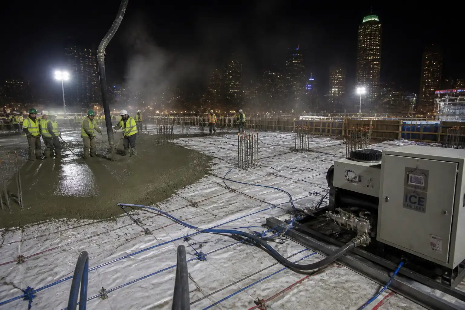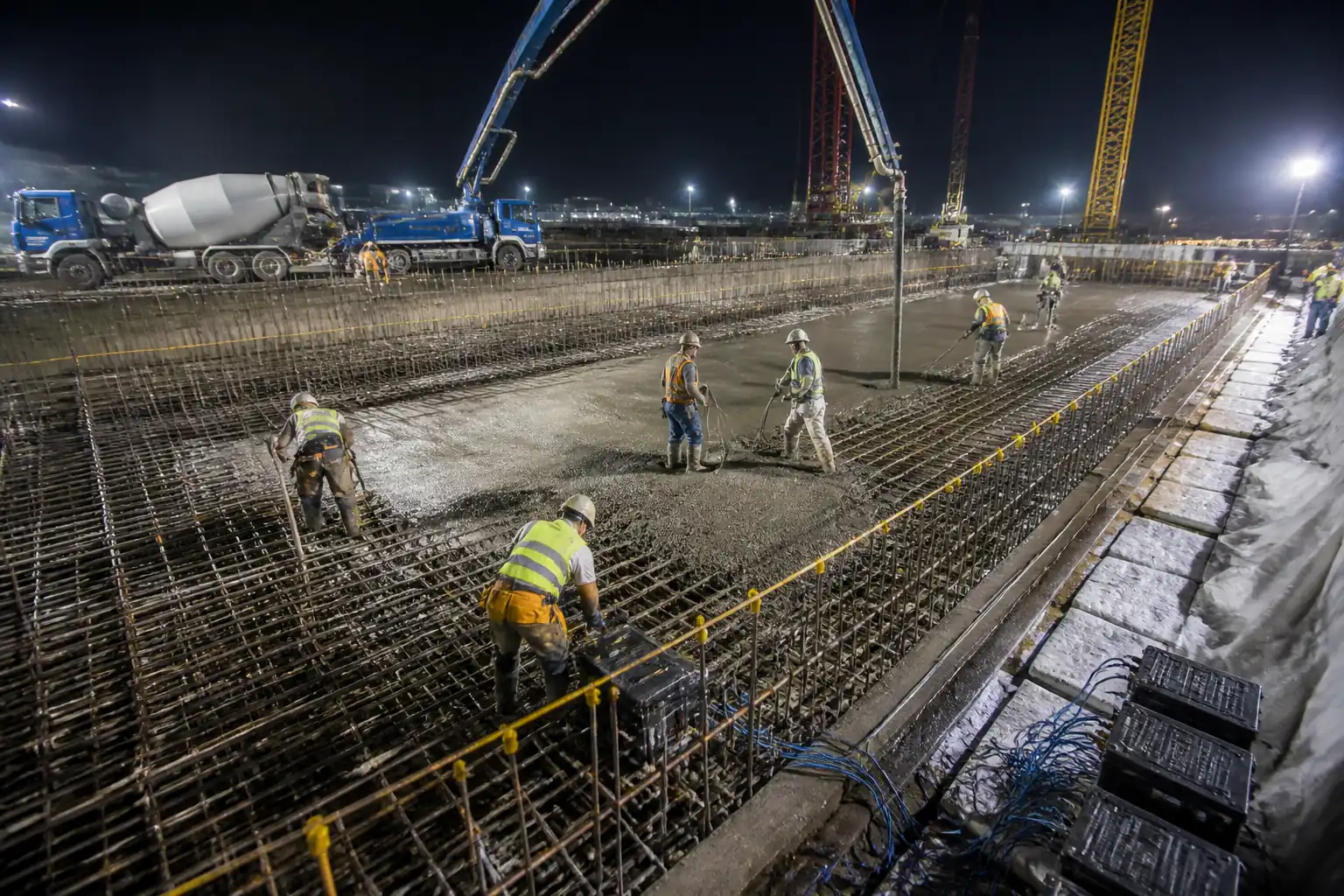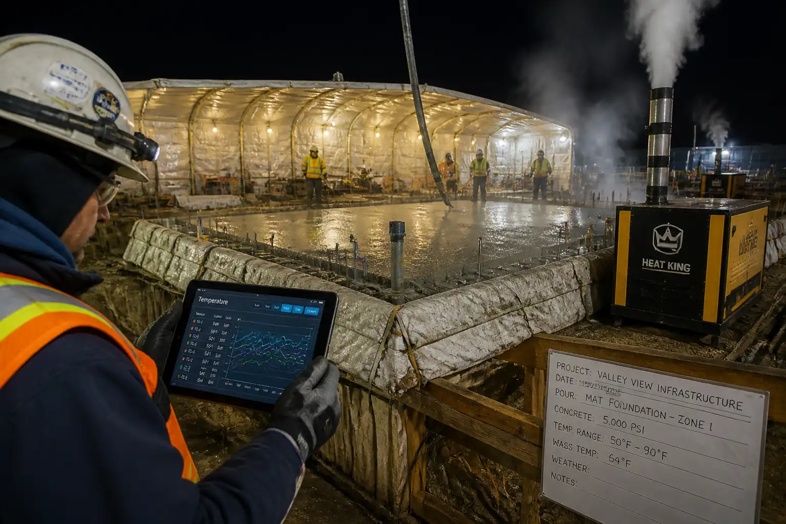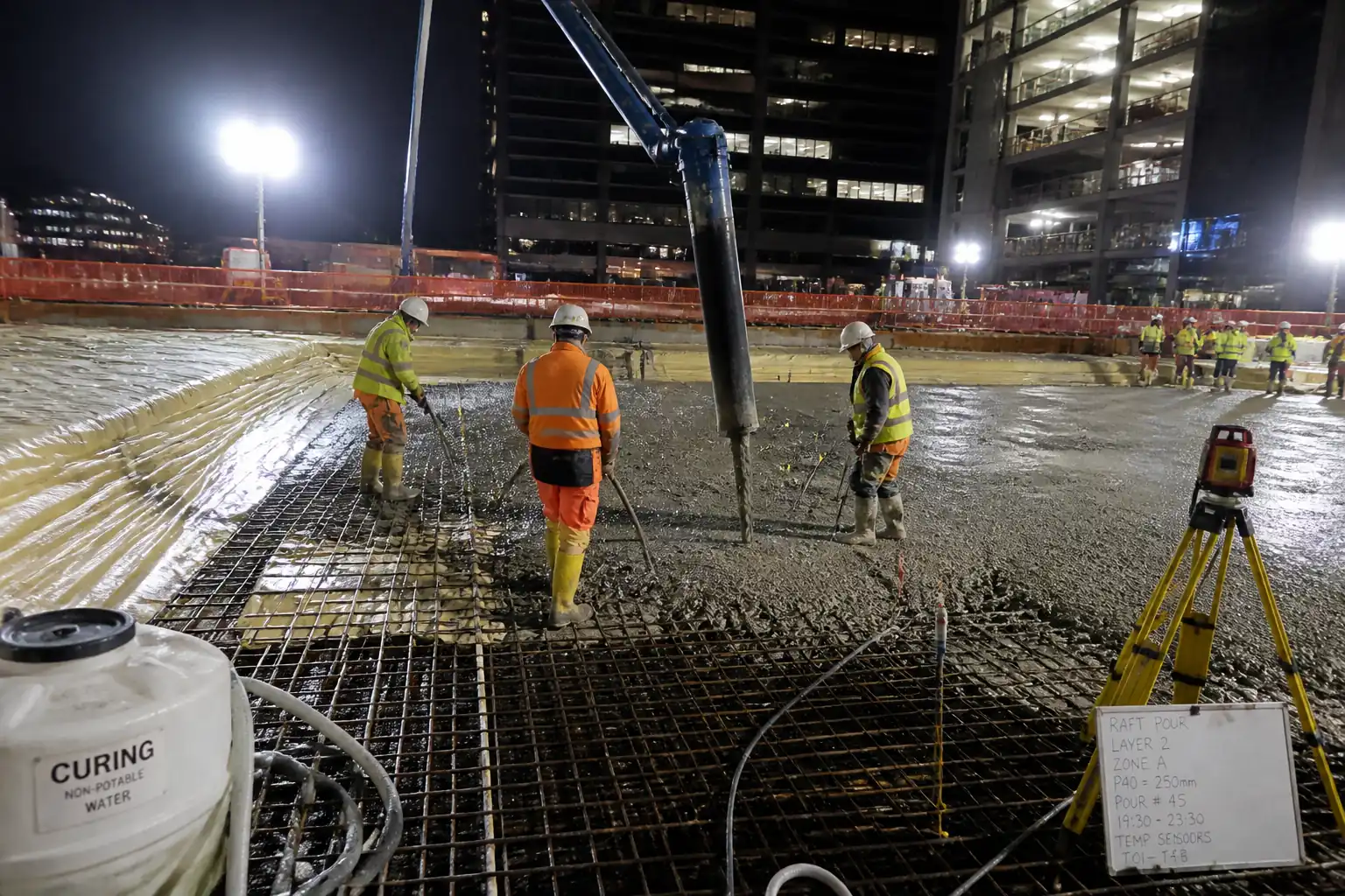
Inspection and Test Plan for Method Statement: Installation and Monitoring of Thermocouples in Mass Concrete
AI-assisted inspection and test plan connected to a method statement, with PDF and Excel export.
More than a static template
Unlike a downloadable Word or PDF template, this ITP is an AI-assisted editable starting point directly connected to its method statement. Every inspection activity, hold point, and acceptance criterion is structured and ready to adapt to your project.
- AI-assisted customization — Tailor inspection activities and acceptance criteria to your specific project scope.
- Linked method statement — This ITP is connected to the corresponding method statement describing the work sequence.
- Multiple export formats — Download as a formatted PDF or editable Excel spreadsheet.
- Editable starting point, not a final document — Review and verify all content against your project specifications and standards before use.
What you can customize
When you save this ITP to your account, every inspection row becomes editable. You can add, remove, or modify:
- Inspection activity — Description of what is being inspected.
- Inspection type — Hold point (H), Witness point (W), Review (R), or Monitor (M).
- Responsibility — Contractor, subcontractor, engineer, or client.
- Frequency — How often the inspection occurs.
- Acceptance criteria — Referenced standard or specification requirement.
- Records — Forms, test reports, or checklists required as evidence.
Why this ITP is used
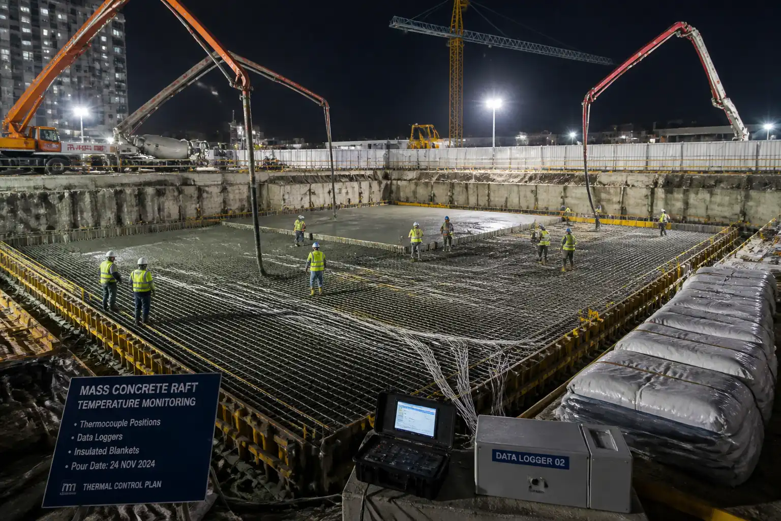
To ensure accurate, reliable temperature monitoring to manage thermal cracking risk in mass concrete.
Who uses this inspection and test plan
QA/QC managers, instrumentation engineers, site engineers, and client representatives.
When this ITP is prepared and submitted
From pre-installation and pre-pour stages through curing, reporting, and final handover.
Who receives or approves this ITP
Engineer/Client Representative for approval prior to works.
Inspection scope
Material receipt, calibration/verification, installation checks, logger setup, monitoring, alarm verification, exceedance management, and reporting.
Typical hold, witness, and review points
Hold: Pre-pour installation, exceedance mitigation approval, formwork removal authorization. Witness: Start of logging and first concrete placed.
Typical inspection records
MIRs, calibration/verification sheets, installation photos, IRs, daily and final thermal reports, as-built drawings, raw data backups.
Important approval note
This ITP is an AI-assisted editable starting point, not a pre-approved document. Before use on any project, all inspection activities, hold points, and acceptance criteria must be reviewed and approved by the relevant parties (superintendent, principal contractor, or client representative) in accordance with your contract and project quality plan.
Always verify acceptance criteria against your applicable drawings, specifications, and regulatory requirements. Hold points must be confirmed with the relevant authority before work proceeds past that point.
Inspection and test plan
| Activity | Inspection / Test | Acceptance Criteria | Responsibility | Record |
|---|---|---|---|---|
| Sensor layout and channel map approval | Review of drawings and schedule; coverage check vs Thermal Control Plan | Approved drawings and schedule; coverage adequate [Verify]. Hold Point. | QA/QC Manager, Engineer/Client Rep | Approved layout, ITP sign-off |
| Material receiving (sensors, connectors, loggers) | Check CoC, calibration certs, IEC 60584 class; visual inspection | Compliant certificates; no damage; correct types/polarity | QA/QC, Stores | MIR, calibration certs |
| Bench verification of sensors | Two-point check (0 °C and ambient/known point) against reference thermometer | Within ±1.5 °C or recorded correction [Verify] | Instrumentation Engineer | Verification sheet |
| Conduit and routing installation | Visual; pull-through; bend radius check | Continuous, protected routes; IP65 terminations | Site Engineer | Pre-pour checklist |
| Sensor fixing and depth verification | Measure depth/offset; photo record | Depth/position within tolerances [Verify]. Hold Point. | Instrumentation Tech + QA/QC + Engineer | IR/ITP form, photos |
| Logger configuration and functional test | Continuity/polarity; baseline stability; clock sync | Stable readings ±0.5 °C; sync ±1 min | Instrumentation Engineer | Setup file, screenshots |
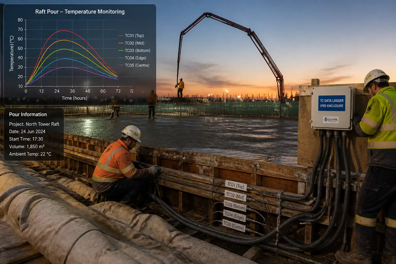
| Start of logging and first concrete placed | Correlation of internal early readings vs ASTM C1064 fresh temperature | Trend consistent; no channel loss. Witness Point. | Site Engineer, QA/QC | Pour log, correlation sheet |
| Monitoring and alarms verification | Alarm trigger test and daily data completeness check | Alarms at 80%/90% set; ≥98% data availability | Instrumentation Engineer | Alarm log, daily report |
| Exceedance event management | Review plots vs limits; mitigation plan approval | Engineer approval prior to resuming related works. Hold Point. | PM, QA/QC, Engineer | NCR (if any), mitigation approval |
| Formwork removal authorization | Trend review last 12–24 h | ΔT and rate-of-cooling within limits [Verify]. Hold/Witness as specified. | Site Engineer, QA/QC, Engineer | Strike permit/authorization |
| Final reporting and as-built submission | Document review | Complete dossier submitted and accepted | Instrumentation Engineer, QA/QC | Final thermal report, as-builts, raw data |
This table is a read-only public reference. Download the PDF or Excel version, or customize this ITP to edit it for your project.
Frequently asked questions
Related method statement
This Inspection and Test Plan is associated with the Method Statement: Installation and Monitoring of Thermocouples in Mass Concrete method statement, which describes the step-by-step construction sequence, resources, materials, equipment, safety controls, and environmental controls for this activity.
View the Method Statement: Installation and Monitoring of Thermocouples in Mass Concrete method statement →Continue with related inspection, method statement, article, and checklist resources.