Method Statement: Installation and Monitoring of Thermocouples in Mass Concrete – Method Statement
AI-assisted method statement with matching ITP, PDF download, and Excel export.
More than a static template
Unlike a downloadable Word or PDF template, this method statement is an AI-assisted editable starting point connected directly to a matching Inspection and Test Plan. Every section is structured, project-adaptable, and ready to export.
- AI-assisted drafting — Customize every section with AI for your specific project scope.
- Linked ITP — A matching inspection and test plan is generated alongside the method statement.
- Multiple export formats — Download as a formatted PDF or editable Excel spreadsheet.
- Editable starting point, not a final document — Review, verify, and adjust all content against your project requirements before use.
Static template vs. Quollnet workflow
| Feature | Static template | Quollnet |
|---|---|---|
| Project-specific content | Manual fill-in required | AI-assisted customization |
| Linked ITP | Separate document, no link | Matching ITP included |
| Export formats | Usually PDF only | PDF and Excel |
| Structured sections | Free-form layout | 13 standardized sections |
| Saved to your account | Local file only | Cloud-saved, reusable |
| Content accuracy | You verify everything | AI-assisted, you still verify |
| Cost | Often free but time-intensive | Free to customize and download |
What you can customize
When you save this method statement to your account, every section becomes editable. The following 13 sections are included:
- Scope — Defines the activity and its boundaries.
- References — Standards, specifications, and drawings.
- Responsibilities — Roles and accountabilities.
- Resources — Labour, plant, and equipment summary.
- Materials — Materials and compliance requirements.
- Equipment — Tools and equipment details.
- Prerequisites — Hold points and pre-conditions.
- Method sequence — Step-by-step construction sequence.
- Safety controls — HSE risk controls and PPE.
- Environmental controls — Environmental mitigation measures.
- QA/QC — Quality inspection and test requirements.
- ITP — Inspection and Test Plan table (has its own page).
- Attachments — Referenced drawings and documentation.
Why this method statement is used
This method statement is used to define and communicate the approved procedure for carrying out method statement: installation and monitoring of thermocouples in mass concrete on site. It ensures the work is planned in advance, the correct resources and controls are in place, and all personnel understand responsibilities, sequence, quality requirements, and safety controls before work begins. It aligns site execution with the documented scope and acceptance expectations.
Who uses this method statement
This method statement is used by contractors, site supervisors, project engineers, QA/QC engineers, HSE officers, consultants, and client representatives. It serves as a shared reference for planning, execution, supervision, inspection, and approval of the activity on site.
When it is prepared and submitted
The method statement is prepared before the work activity starts and submitted as part of the pre-construction documentation package for review and approval.
Who reviews or approves it
The method statement is usually submitted to the client representative, consultant, resident engineer, or project management consultant for review and approval before the work commences.
Important approval note
This method statement is an AI-assisted editable starting point, not a pre-approved document. Before use on any project, all content must be reviewed and approved by the relevant parties (superintendent, principal contractor, or client representative) in accordance with your contract and project quality plan.
For example: if your specification requires a departure from a referenced standard, that departure must be documented and approved separately — this method statement will not capture that automatically. Always verify against your applicable drawings, specifications, and regulatory requirements.
Method statement content
Scope
Purpose
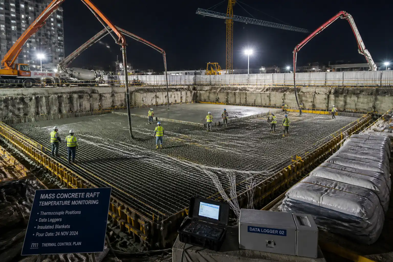
Define the method to install, calibrate, map, commission, and monitor thermocouples embedded in mass concrete to control early-age temperature, manage peak and differential limits, record data, and report. Includes hold points when limits are approached or exceeded and procedures for mitigation.
Scope of Application
- Mass concrete placements (e.g., rafts, thick pile caps, transfer beams, abutments, spillways) where heat of hydration may cause thermal cracking.
- Thermocouple types and data loggers suitable for concrete monitoring.
- Pre-pour through demobilization, including reporting and as-built documentation.
Key Objectives
- Verify sensor accuracy and positions.
- Monitor internal and surface temperatures at specified intervals.
- Control and document peak core temperature and core–surface differential.
- Trigger hold points and mitigation when thresholds are approached/exceeded [Verify per project specifications].
Exclusions
- Active cooling pipe design/operation (covered by separate thermal control plan where applicable).
- Structural design responsibilities.
References
| Document Type | Reference / Number | Revision | Notes |
|---|---|---|---|
| Standard | ACI 207.1R, ACI 207.2R | Primary guidance for temperature limits and control of mass placements [Verify per project specifications]. | |
| Standard | ACI 301, ACI 305R, ACI 306R | Relevant to placement conditions affecting temperature rise and curing. | |
| Standard | BS EN 206, BS EN 13670 | Execution tolerances and conformity for European projects. | |
| Guidance | CIRIA C660 | Determination of permissible temperature differentials and restraint conditions. | |
| Standard | IEC 60584-1/-2 | Accuracy classes (e.g., Class 1) and type K/T performance. | |
| Standard | ASTM C1064 | Used to correlate initial internal readings post-placement. | |
| Standard | ASTM C1074 | Applicable if maturity or strength estimation is required via same sensors [Verify per project specifications]. | |
| Standard | ISO 9001, ISO 14001, ISO 45001 | Management framework for QA/QC and HSE. |
Responsibilities
| Role | Responsibility | Name / Party |
|---|---|---|
| PM | Contractor Project Manager | Contractor |
| QA/QC | QA/QC Manager | Contractor |
| Instrumentation | Instrumentation Engineer / Technician | Contractor |
| Survey | Surveyor | Contractor |
| Construction | Concrete Superintendent / Site Engineer | Contractor |
| HSE | HSE Manager / Officer | Contractor |
| Client | Engineer/Client Representative | Engineer |
Resources
| Resource Type | Description | Quantity | Remarks |
|---|---|---|---|
| Personnel | Leads thermocouple system design and commissioning. | 1 | |
| Personnel | Installation, terminations, testing, data handling. | 2-4 | |
| Personnel | Set-out and as-built mapping. | 1 | |
| Personnel | Construction interface and protection during pour. | 1-2 | |
| Personnel | Task-specific HSE controls and permits. | 1 |
Materials
| Material | Specification / Grade | Quantity | Remarks |
|---|---|---|---|
| Thermocouple | Type K, Class 1 | As per sensor layout +10% spare | |
| Extension wire | IEC 60584-3 | As required | |
| Connectors | IEC 60584 compatible | Per channel + spares | |
| Conduit | IP65 | As required | |
| Accessories | As required | ||
| Insulation | As required |
Equipment
| Equipment | Capacity / Type | Quantity | Inspection Required |
|---|---|---|---|
| Data logger | 8–32 ch | As per channels + 1 spare | |
| Reference thermometer | 1 | ||
| Calibrator | 1 | ||
| Tester | 1 | ||
| Survey gear | As required |
Prerequisites
- Approved Method Statement, ITP, and Thermal Control Plan [Verify per project specifications].
- Approved sensor layout drawing indicating ID, depth, and offset from faces/corners.
- Current calibration certificates for loggers and reference thermometer (≤12 months old) and verification plan.
- Approved concrete mix design, pour sequence, rates, and curing plan (including insulation strategy).
- Power supply and/or batteries for loggers with autonomy ≥ duration of monitoring + 48 h.
- Communication plan for alarms (SMS/email) if remote monitoring is used.
- Weather forecast reviewed for 72 h window; hot/cold-weather measures ready.
- Permits to Work: Electrical (temporary power), Working at Height, and Pour Permit [Verify per project HSE plan and local regulations].
- Toolbox Talk completed for all personnel; sample installation mock-up reviewed.
- Materials staged and pre-cut; conduits routed to safe accessible termination points.
- RFI/Inspection Request raised for pre-pour installation inspection (Hold Point).
Method Sequence
| Step | Activity | Description | Responsibility | Inspection / Hold Point |
|---|---|---|---|---|
| 1 | Planning and layout confirmation | Review design, thermal model, and define sensor count, locations (core, quarter-depth, near-surface ~50±10 mm), corners, and any restrained interfaces. Prepare channel schedule with IDs and logger mapping. | Instrumentation Engineer, Site Engineer | Document review |
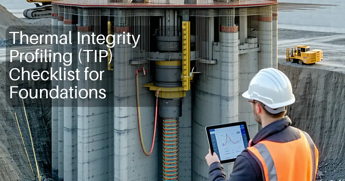
| 2 | Pre-assembly and bench verification | Label all sensors; verify polarity; perform two-point check (0 °C ice bath and ambient) vs reference thermometer; record offsets if any. | Instrumentation Technician | QA witness |
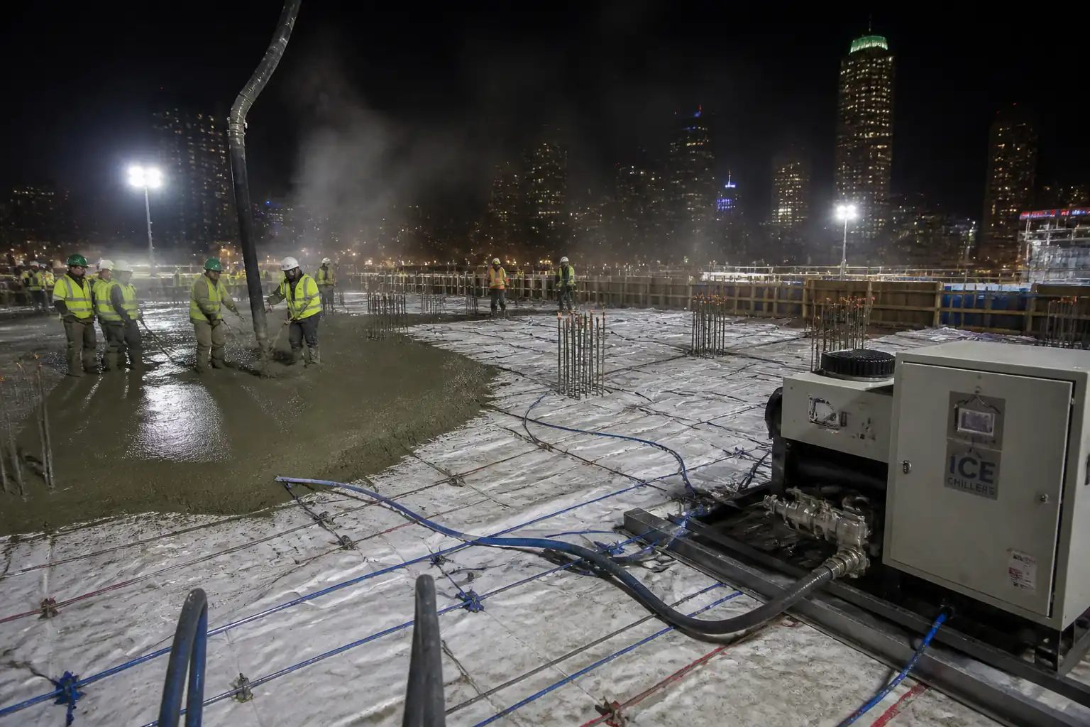
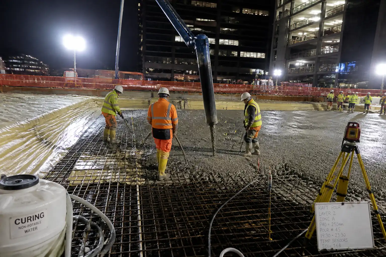
| 3 | Conduit installation and cable routing | Install flexible conduit from each sensor location to accessible face/top; avoid crushing points; minimum bend radius 6× cable Ø; secure every ~0.5 m. | Site Engineer | In-process |
| 4 | Thermocouple fixing at location | Fix welded tip at specified depth with non-corroding ties; protect junction using small foam plug or tape to prevent paste infiltration; mark tag with ID and depth. | Instrumentation Technician | Pre-pour inspection (Hold) |
| 5 | Terminations and logger setup | Run extension leads to junction box and data logger; connect via type K connectors; enable cold junction compensation; set project time, channel names/IDs, sampling interval. | Instrumentation Engineer | Functional check |
| 6 | Pre-pour verification (Hold Point) | Joint inspection of sensor positions, tag IDs, conduit, logger configuration; lock channels. | QA/QC + Client Rep | Hold point |
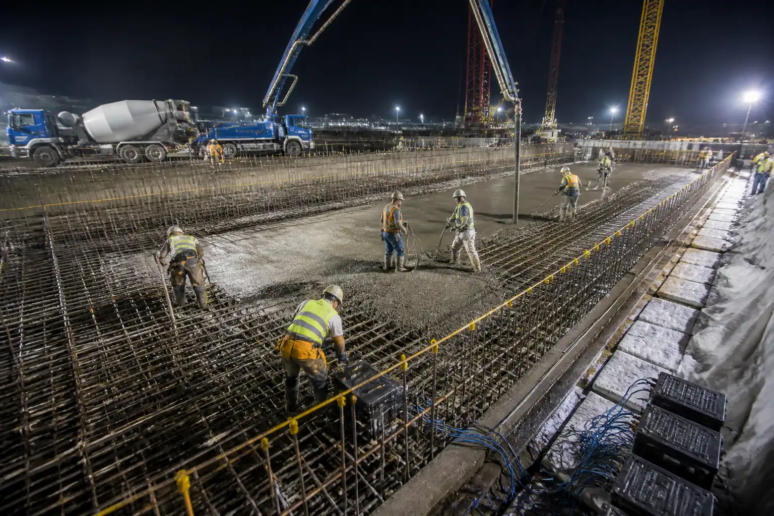
| 7 | Concrete placement interface | Start data logging 30–60 min before first delivery; during placement protect cables from pumps/vibrators; re-verify readings after first 10% volume placed. | Site Engineer + Instrumentation | Witness |
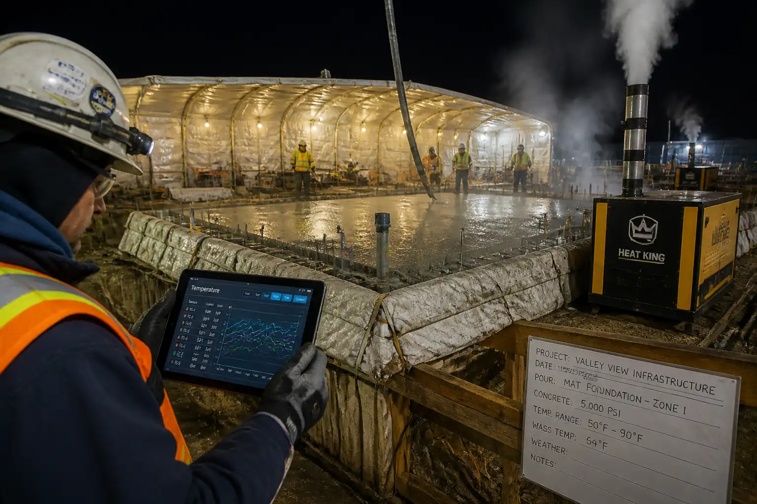
| 8 | Curing and insulation control | Apply insulation/curing as per thermal plan; record start/end times; ensure surface thermocouples remain covered but accessible. | Site Engineer | Routine |
| 9 | Monitoring regime and alarms | Logging intervals: 10 min for first 72 h; hourly thereafter until peak passes and ΔT < limit for 24 h [Verify]. Configure alarms at 80% (awareness) and 90% (action) of limits for Tmax and ΔT. | Instrumentation Engineer | Remote/onsite check |
| 10 | Exceedance response (Hold) | If alarm >=90% of limit: notify Engineer; intensify insulation or staged cooling; if >100%: declare hold, pause further lifts/striking; implement mitigation and revised plan. | PM/QA/QC/Engineer | Hold point |
| 11 | Formwork removal check | Before striking, confirm ΔT and absolute temperatures within limits and rate-of-cooling acceptable to avoid shock. | Site Engineer + QA/QC | Hold/Witness as specified |
| 12 | Data management and reporting | Daily report during first 7 days: min/max, ΔT per sensor pair, rate-of-rise, comparison to limits, alarm log, actions taken. Final report with charts and as-built map. | Instrumentation Engineer | QA review |
| 13 | Demobilization and as-built | After monitoring completion, disconnect loggers; seal conduit ends; submit as-builts with coordinates, elevations, sensor IDs, and depths. | Instrumentation + Survey | Final |
Health, Safety and Environment - Safety Controls
Task-specific hazards and controls
- Hazard: Working at height on formwork/edges while routing cables.
- Likely consequence: Falls causing serious injury.
- Engineering/procedural control: Provide collective edge protection or temporary guardrails; use MEWP or podium steps where feasible; maintain 3-point contact on ladders used only for access; install fall arrest anchor points if required.
- Required PPE: Full-body harness with double lanyards when no collective protection; hard hat with chin strap; anti-slip footwear; gloves.
- Collective preventive measure: Installed edge protection and access platforms planned in lift drawings.
-
Inspection/permit/supervision: Working at Height permit; pre-use inspection of MEWP/ladders; Supervisor to brief and monitor [Verify per project HSE plan and local regulations].
-
Hazard: Entanglement and cable damage during pumping/vibration/finishing.
- Likely consequence: Loss of monitoring, electrical short, trip hazards.
- Engineering/procedural control: Pre-route cables away from traffic; secure at 0.5 m spacing; use protective conduits and cover crossing points; designate cable marshal during pour.
- Required PPE: Gloves, safety boots, eye protection.
- Collective preventive measure: Physical barriers and marked cable routes; exclusion zones near pump lines.
-
Inspection/permit/supervision: Pour Permit; continuous supervision by Site Engineer.
-
Hazard: Electrical hazard from powered data loggers and temporary electrics.
- Likely consequence: Electric shock, fire.
- Engineering/procedural control: Use IP65 enclosures, RCD-protected circuits, 24 VDC preferred; proper cable glands and strain relief; no exposed conductors.
- Required PPE: Insulated gloves when working on panels; eye protection.
- Collective preventive measure: Lockable weatherproof cabinets; labeling and isolation points.
-
Inspection/permit/supervision: Electrical PTW; weekly inspection and PAT/visual checks; competent electrician oversight.
-
Hazard: Rebar puncture/cuts during fixing sensors.
- Likely consequence: Lacerations, hand injuries.
- Engineering/procedural control: Deburr rebar tails; use rebar caps; use stainless tie-wire and proper twisting tools.
- Required PPE: Cut-resistant gloves, long sleeves, eye protection.
- Collective preventive measure: Rebar capping plan across working area.
-
Inspection/permit/supervision: Pre-task inspection by Supervisor.
-
Hazard: Cementitious burns and splash during placement and curing.
- Likely consequence: Chemical burns, eye injury.
- Engineering/procedural control: Avoid handling fresh concrete without protection; provide wash stations and neutralizing wipes.
- Required PPE: Alkali-resistant gloves, long sleeves, safety goggles/face shield.
- Collective preventive measure: Designated washout and hygiene facilities.
-
Inspection/permit/supervision: HSE inspections during pour; first-aid readiness.
-
Hazard: Manual handling of cable drums, loggers, batteries.
- Likely consequence: Strains, sprains.
- Engineering/procedural control: Use trolleys; split loads; team lift over 20 kg; plan delivery points adjacent to workface.
- Required PPE: Gloves, safety boots.
- Collective preventive measure: Mechanical aids available.
-
Inspection/permit/supervision: Manual handling training verified.
-
Hazard: Noise from vibrators and pumps.
- Likely consequence: Hearing damage.
- Engineering/procedural control: Keep non-essential staff away; limit exposure time.
- Required PPE: Hearing protection (ear defenders/plugs) SNR appropriate.
- Collective preventive measure: Equipment maintenance to reduce noise.
-
Inspection/permit/supervision: Noise assessment available on site.
-
Hazard: Night works/poor visibility for continuous monitoring.
- Likely consequence: Trips/falls, struck-by incidents.
- Engineering/procedural control: Task lighting ≥200 lux; reflective barriers; clear walkways.
- Required PPE: High-visibility clothing, headlamps where needed.
- Collective preventive measure: Temporary lighting towers positioned off access routes.
- Inspection/permit/supervision: Night-work permit; lighting inspection log.
Health, Safety and Environment - Environmental Controls
- Potential impact: Cable/connector packaging waste and offcuts.
- Control: Segregate plastics/metals; minimize offcuts via pre-measurement; return unused reels to stores.
-
Monitoring: Waste skip log; site audits.
-
Potential impact: Battery disposal from data loggers.
- Control: Use rechargeable packs where feasible; dispose via licensed recycler; maintain battery register.
-
Monitoring: Waste transfer notes retained.
-
Potential impact: Generator noise/emissions for powered loggers or lighting.
- Control: Use mains or battery/solar where possible; position generators away from receptors; fit acoustic shrouds.
-
Monitoring: Noise spot checks; fuel logs; spill kits nearby.
-
Potential impact: Concrete washout and alkaline runoff during curing operations.
- Control: Use lined washout pits; prevent runoff near logger enclosures and conduits.
-
Monitoring: Daily inspection during pour and first 48 h.
-
Potential impact: Disturbance of wildlife from night lighting.
- Control: Directional, shielded lighting; avoid unnecessary illumination.
-
Monitoring: HSE/environmental checks.
-
Compliance: Follow ISO 14001 EMS and local environmental permits [Verify per project HSE plan and local regulations].
Quality Assurance / Quality Control
Acceptance criteria and tolerances
- Sensor accuracy: IEC 60584 Class 1 for Type K (±1.5 °C or ±0.4% of reading) [Verify].
- Depth tolerance: Core mid-thickness ±50 mm; near-surface 50±10 mm from formed face; horizontal ±100 mm [Verify].
- Logger accuracy: ≤±0.5 °C; clock sync within ±1 min of site time.
- Data completeness: ≥98% during first 7 days; no gap >30 min in first 72 h.
- Limits (typical, verify): Tmax 65–75 °C; ΔT core-to-surface 20–25 °C; rate-of-cooling ≤2–5 °C/h before strike.
Calibration and verification
- Certificates for loggers/reference thermometer current (≤12 months).
- Field two-point verification for ≥10% of sensors or minimum 3 per pour lot [Verify].
- Record any channel-specific offset; apply in software if supported (do not mix sensor types on a logger).
Identification and traceability
- Unique Sensor ID format: -- (e.g., RF1-C3-CORE).
- Channel map linking Sensor ID to logger channel and coordinates/elevation.
- Photographic records prior to pour showing tag and placement.
Data integrity and reporting
- File format: CSV/JSON with ISO 8601 timestamps; timezone noted.
- Backups: Daily to server/cloud with checksum verification.
- Daily thermal report: plots (core and surface), tabulated Tmax/ΔT, alarms, actions.
- Final report: executive summary, methods, sensor map, charts, conclusions, NCRs/mitigations.
Nonconformance and corrective action
- Causes: sensor damage, drift, wrong position, data gaps, exceedances.
- Actions: repair/replace before pour (if feasible); apply engineering judgment if a single sensor fails but redundancy exists; for exceedance, issue NCR and implement mitigation/revised plan approved by Engineer.
Hold and witness points
- Hold: Pre-pour installation; Exceedance management approval; Formwork removal authorization.
- Witness: Start of logging; first concrete placed; daily report review.
Attachments
- Example sensor layout and channel schedule (editable).
- Pre-pour thermocouple installation checklist.
- Logger configuration template and alarm matrix.
- Daily thermal report template (plots and summary tables).
- Exceedance response workflow and communication tree.
- As-built survey template for sensor coordinates/elevations.
- Manufacturer datasheets: thermocouples, connectors, data loggers.
- Calibration/verification forms and sample completed sheets.
- Risk assessment and method-specific PTW samples.
This content is a read-only public reference. Download or customize to get an editable version.
ITP preview
The first inspection activities from the linked ITP for Method Statement: Installation and Monitoring of Thermocouples in Mass Concrete:
| Activity | Inspection / Test | Acceptance Criteria | Responsibility | Record |
|---|---|---|---|---|
| Sensor layout and channel map approval | Review of drawings and schedule; coverage check vs Thermal Control Plan | Approved drawings and schedule; coverage adequate [Verify]. Hold Point. | QA/QC Manager, Engineer/Client Rep | Approved layout, ITP sign-off |
| Material receiving (sensors, connectors, loggers) | Check CoC, calibration certs, IEC 60584 class; visual inspection | Compliant certificates; no damage; correct types/polarity | QA/QC, Stores | MIR, calibration certs |
| Bench verification of sensors | Two-point check (0 °C and ambient/known point) against reference thermometer | Within ±1.5 °C or recorded correction [Verify] | Instrumentation Engineer | Verification sheet |
Showing 3 of 11 inspection activities. View full ITP →
Related Inspection and Test Plan
An Inspection and Test Plan (ITP) is available for Method Statement: Installation and Monitoring of Thermocouples in Mass Concrete. The ITP defines the inspection activities, acceptance criteria, hold and witness points, responsible parties, and records required to verify the work described in this method statement.
View the Method Statement: Installation and Monitoring of Thermocouples in Mass Concrete ITP →Frequently asked questions
Continue with related Quollnet resources connected to this method statement.