Inspection and Test Plan for Method Statement: Thermal Cracking Control for Mass Concrete (Pre-cooling, Post-cooling Pipes, Insulation, and Temperature Monitoring)
AI-assisted inspection and test plan connected to a method statement, with PDF and Excel export.
More than a static template
Unlike a downloadable Word or PDF template, this ITP is an AI-assisted editable starting point directly connected to its method statement. Every inspection activity, hold point, and acceptance criterion is structured and ready to adapt to your project.
- AI-assisted customization — Tailor inspection activities and acceptance criteria to your specific project scope.
- Linked method statement — This ITP is connected to the corresponding method statement describing the work sequence.
- Multiple export formats — Download as a formatted PDF or editable Excel spreadsheet.
- Editable starting point, not a final document — Review and verify all content against your project specifications and standards before use.
What you can customize
When you save this ITP to your account, every inspection row becomes editable. You can add, remove, or modify:
- Inspection activity — Description of what is being inspected.
- Inspection type — Hold point (H), Witness point (W), Review (R), or Monitor (M).
- Responsibility — Contractor, subcontractor, engineer, or client.
- Frequency — How often the inspection occurs.
- Acceptance criteria — Referenced standard or specification requirement.
- Records — Forms, test reports, or checklists required as evidence.
Why this ITP is used
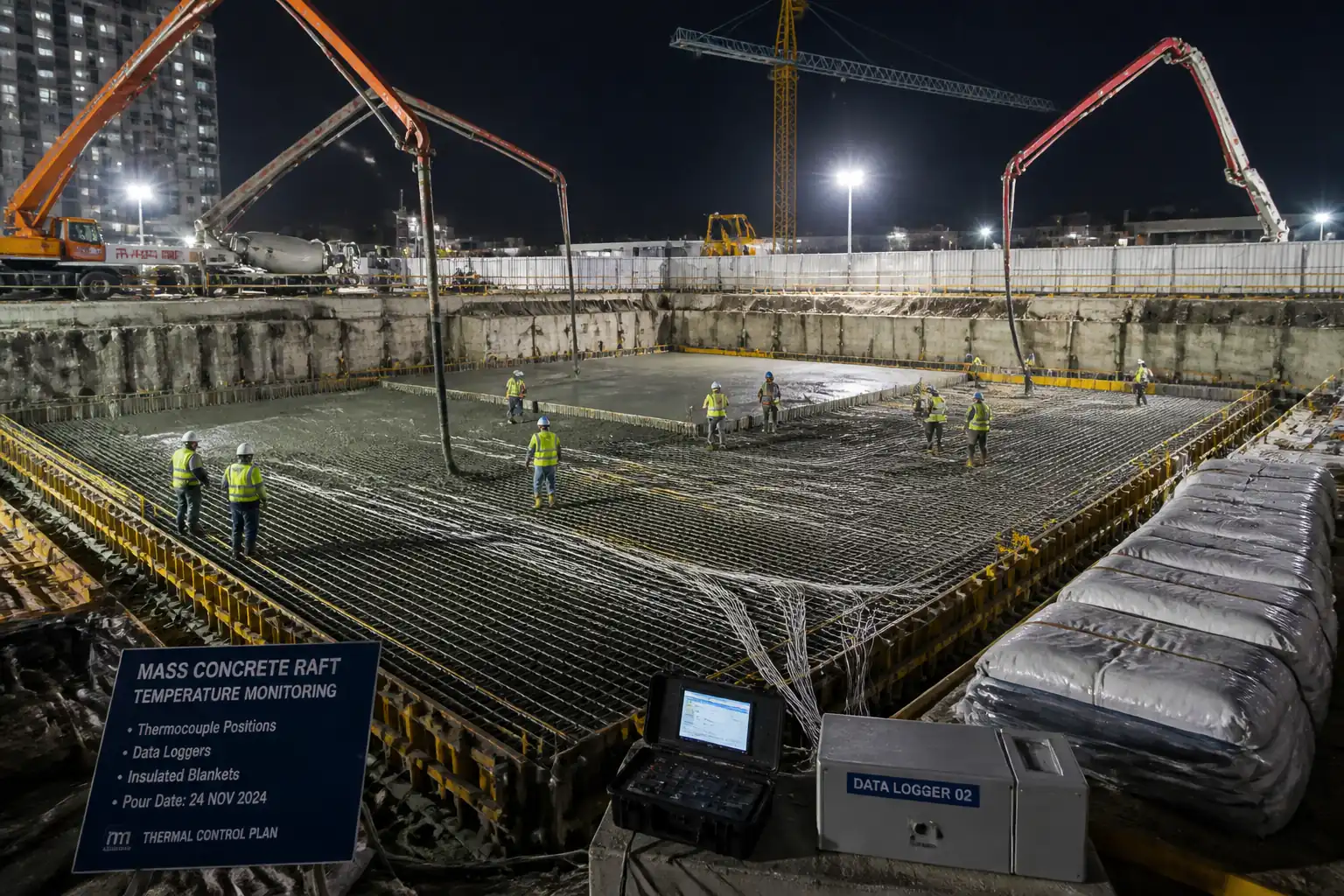
To verify that mass concrete temperatures remain within approved limits, preventing early-age thermal cracking and durability issues.
Who uses this inspection and test plan
QA/QC teams, Thermal Control Engineers, MEP Supervisors, and the Engineer/Consultant for witnessing and approvals.
When this ITP is prepared and submitted
From preconstruction through placement, peak temperature period, ramp-down, and final demobilization.
Who receives or approves this ITP
Engineer/Consultant and Client Representative for approvals and witnessing.
Inspection scope
Covers plan approvals, materials and shop drawings, hydrotesting of cooling circuits, sensor calibration, fresh concrete testing, monitoring review, and close-out.
Typical hold, witness, and review points
H1 Plan approval; H2 Pipe pressure test; H3 Sensor installation/calibration; H4 Start of post-cooling; H5 End of cooling/insulation removal.
Typical inspection records
Approved plans, calibration certificates, hydrotest records, field test reports, daily thermal logs, alarm/action records, as-builts, final acceptance memo.
Important approval note
This ITP is an AI-assisted editable starting point, not a pre-approved document. Before use on any project, all inspection activities, hold points, and acceptance criteria must be reviewed and approved by the relevant parties (superintendent, principal contractor, or client representative) in accordance with your contract and project quality plan.
Always verify acceptance criteria against your applicable drawings, specifications, and regulatory requirements. Hold points must be confirmed with the relevant authority before work proceeds past that point.
Inspection and test plan
| Activity | Inspection / Test | Acceptance Criteria | Responsibility | Record |
|---|---|---|---|---|
| Approval of Thermal Control Plan (H1) | Review of plan, model outputs, acceptance limits, response actions | Plan approved; limits stated (Tplace, Tcore,max, ΔT, rates) [Verify] | QA/QC Manager; Engineer | Approved plan, ITP sign-off |
| Cooling Pipe Materials and Shop Drawings | Submittal review vs specifications | Materials and layout comply with approved design | MEP Supervisor; Engineer | Approved submittal |
| Pressure Test of Cooling Circuits (H2) | Hydrostatic test to 1.5× operating pressure for 30 min | No leaks; pressure drop ≤ 0.1 bar/30 min [Verify] | MEP Supervisor; QA/QC; Engineer | Pressure test certificate, gauge calibration |
| Sensor Installation & Calibration (H3) | Function test; ice-point calibration; channel verification | Accuracy ±0.5°C; logging interval ≤ 15 min; IDs mapped | Instrumentation Technician; QA/QC; Engineer | Calibration sheets; sensor layout |
| Trial Batch / Pre-cooling Verification | Measure Tplace, slump/air; verify plant chilling capacity | Tplace meets target; workability per mix | QA/QC; Ready-Mix Supplier; Engineer | Trial batch report |
| Concrete Delivery and Fresh Tests | ASTM C1064, C143, C231/C173; time stamps | Tplace ≤ 18–21°C; slump/air within tolerance [Verify] | QA/QC Inspector | Field test reports; batch tickets |
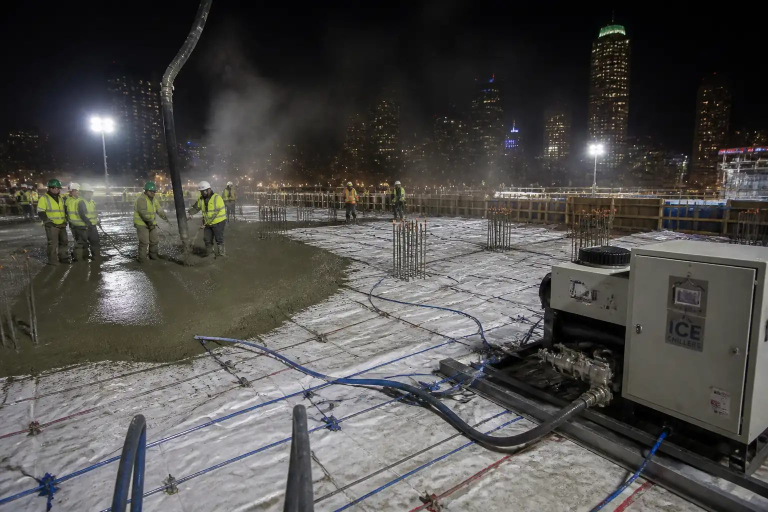
| Start of Post-cooling (H4) | Flow/pressure check; supply/return temperatures | Stable flow 1–3 L/min per circuit; outlet 2–7°C; no leaks | MEP Supervisor; Thermal Control Engineer; Engineer | Cooling start log |
| Daily Temperature Monitoring Review | Automated log review; alarm audit | No exceedances or corrective action documented within 30 min | Thermal Control Engineer; QA/QC | Daily thermal report |
| Cooling Ramp-down Authorization | Trend analysis of last 24–48 h | ΔT trending down; rates within limits | Thermal Control Engineer; Engineer | Ramp-down approval note |
| End of Cooling and Insulation Removal (H5) | Final review of ΔT and core temps; visual inspection | ΔT ≤ 10°C; stable temps; surface intact | Construction Manager; MEP Supervisor; Engineer | Final acceptance memo; flushing certificate |
| Compressive Strength / Maturity Verification | ASTM C39 / EN 12390; maturity (if used) per ASTM C1074 | Strength per spec; curing adequacy | QA/QC | Lab test reports; maturity charts |
This table is a read-only public reference. Download the PDF or Excel version, or customize this ITP to edit it for your project.
Frequently asked questions
Related method statement
This Inspection and Test Plan is associated with the Method Statement: Thermal Cracking Control for Mass Concrete (Pre-cooling, Post-cooling Pipes, Insulation, and Temperature Monitoring) method statement, which describes the step-by-step construction sequence, resources, materials, equipment, safety controls, and environmental controls for this activity.
View the Method Statement: Thermal Cracking Control for Mass Concrete (Pre-cooling, Post-cooling Pipes, Insulation, and Temperature Monitoring) method statement →Continue with related inspection, method statement, article, and checklist resources.