Method Statement: Installation of Heavy Steel Reinforcement for Thick Raft Foundations and Pile Caps – Method Statement
AI-assisted method statement with matching ITP, PDF download, and Excel export.
More than a static template
Unlike a downloadable Word or PDF template, this method statement is an AI-assisted editable starting point connected directly to a matching Inspection and Test Plan. Every section is structured, project-adaptable, and ready to export.
- AI-assisted drafting — Customize every section with AI for your specific project scope.
- Linked ITP — A matching inspection and test plan is generated alongside the method statement.
- Multiple export formats — Download as a formatted PDF or editable Excel spreadsheet.
- Editable starting point, not a final document — Review, verify, and adjust all content against your project requirements before use.
Static template vs. Quollnet workflow
| Feature | Static template | Quollnet |
|---|---|---|
| Project-specific content | Manual fill-in required | AI-assisted customization |
| Linked ITP | Separate document, no link | Matching ITP included |
| Export formats | Usually PDF only | PDF and Excel |
| Structured sections | Free-form layout | 13 standardized sections |
| Saved to your account | Local file only | Cloud-saved, reusable |
| Content accuracy | You verify everything | AI-assisted, you still verify |
| Cost | Often free but time-intensive | Free to customize and download |
What you can customize
When you save this method statement to your account, every section becomes editable. The following 13 sections are included:
- Scope — Defines the activity and its boundaries.
- References — Standards, specifications, and drawings.
- Responsibilities — Roles and accountabilities.
- Resources — Labour, plant, and equipment summary.
- Materials — Materials and compliance requirements.
- Equipment — Tools and equipment details.
- Prerequisites — Hold points and pre-conditions.
- Method sequence — Step-by-step construction sequence.
- Safety controls — HSE risk controls and PPE.
- Environmental controls — Environmental mitigation measures.
- QA/QC — Quality inspection and test requirements.
- ITP — Inspection and Test Plan table (has its own page).
- Attachments — Referenced drawings and documentation.
Why this method statement is used
This method statement is used to define and communicate the approved procedure for carrying out method statement: installation of heavy steel reinforcement for thick raft foundations and pile caps on site. It ensures the work is planned in advance, the correct resources and controls are in place, and all personnel understand responsibilities, sequence, quality requirements, and safety controls before work begins. It aligns site execution with the documented scope and acceptance expectations.
Who uses this method statement
This method statement is used by contractors, site supervisors, project engineers, QA/QC engineers, HSE officers, consultants, and client representatives. It serves as a shared reference for planning, execution, supervision, inspection, and approval of the activity on site.
When it is prepared and submitted
The method statement is prepared before the work activity starts and submitted as part of the pre-construction documentation package for review and approval.
Who reviews or approves it
The method statement is usually submitted to the client representative, consultant, resident engineer, or project management consultant for review and approval before the work commences.
Important approval note
This method statement is an AI-assisted editable starting point, not a pre-approved document. Before use on any project, all content must be reviewed and approved by the relevant parties (superintendent, principal contractor, or client representative) in accordance with your contract and project quality plan.
For example: if your specification requires a departure from a referenced standard, that departure must be documented and approved separately — this method statement will not capture that automatically. Always verify against your applicable drawings, specifications, and regulatory requirements.
Method statement content
Scope
Work Included
- Installation of heavy steel reinforcement for thick raft foundations and pile caps, including bottom and top reinforcement mats, shear reinforcement, column starter bars, and mechanical splices/couplers where specified.
- Provision and installation of compliant concrete spacers, cover blocks, and heavy-duty chairs/supports for maintaining required concrete cover and bar positioning.
- Alignment control for column starter bars, dowels to pile heads/walls, and embed coordination.
- Compliance with lap splices or mechanical couplers per design and standard requirements.
- Pre-pour inspections, hold/witness points, rectification, and final release for concreting.
Work Excluded
- Formwork/shuttering, excavation, ground improvement, blinding concrete, and concrete placement activities other than readiness checks.
- Permanent works design; all bar sizes, grades, splice lengths, and coupler locations are per Issued for Construction (IFC) drawings and specifications [Verify per project].
Locations
- Thick raft foundations and pile caps as designated in IFC drawings and bar bending schedules (BBS).
References
| Document Type | Reference / Number | Revision | Notes |
|---|---|---|---|
| Design & Execution Codes | |||
| Rebar Materials & Detailing | |||
| Splices/Welding | |||
| Spacers/Chairs | |||
| Management Systems |
Responsibilities
| Role | Responsibility | Name / Party |
|---|---|---|
| Contractor PM | Approves method, ensures interfaces coordinated, ensures permits. | Contractor |
| CM | Implements sequence, liaises with QC/Survey, ensures safe access and craneage. | Contractor |
| Engineer | Sets out, verifies cover/spacing, controls interfaces and embeds. | Contractor |
| QA/QC | Material verification, ITP compliance, hold/witness coordination, NCRs. | Contractor |
| HSE | TBTs, permits, inspections, monitoring of controls. | Contractor |
| Survey | Grid transfer, elevations, starter bar alignment templates. | Contractor |
| Foreman | Correct fixing, chairing, tying, lap/coupler execution. | Contractor |
| Lab | Sampling, testing per standards. | Third Party |
| Consultant | Witness/hold inspections, IR approvals. | Engineer |
Resources
| Resource Type | Description | Quantity | Remarks |
|---|---|---|---|
| Manpower | Skilled steel fixers for heavy bar installation. | As required | |
| Manpower | Certified riggers for lifting rebar bundles/cages. | 2–4 | |
| Manpower | Certified operator for mobile crane. | 1 | |
| Manpower | Per shift coverage for inspections/records. | 1–2 | |
| Manpower | Surveyor + assistant with total station. | 1 crew |
Materials
| Material | Specification / Grade | Quantity | Remarks |
|---|---|---|---|
| Rebar | Dia per BBS; standard lengths | Store off ground, protected. | |
| Couplers | Bar-size matched | ||
| Binding wire | |||
| Concrete spacers | 75 mm typical for raft/pile caps [Verify] | ||
| Chairs/supports | Heights: 75–500 mm [Verify] | ||
| Safety caps |
Equipment
| Equipment | Capacity / Type | Quantity | Inspection Required |
|---|---|---|---|
| Crane | As per lift plan | Yes | |
| Bender/Cutter | Bar dia per spec | Yes | |
| Tying tools | Yes | ||
| Survey set | Yes | ||
| Torque wrench | Per bar size | Yes | |
| Rigging gear | Per lift plan | Yes | |
| Hand tools | Yes | ||
| Platforms | Yes |
Prerequisites
- Approved IFC drawings, bar bending schedules (BBS), method statement, ITP, lift plans, and risk assessments [Verify per project].
- Material approvals: MIR for rebar, couplers, spacers/chairs, tie wire; mill certificates and test results accepted.
- Blinding concrete/raft base prepared, cleaned, surveyed; construction joints and kickers (if any) set out and cured.
- Benchmarks and grid lines transferred and protected. Reference elevations established.
- Permits: Lifting, Hot Works (if cutting/welding permitted), Night Work, Confined Space (if within deep excavations), and Work at Height [Verify per HSE plan and local regulations].
- Coordination: openings, sleeves, grounding, waterstops, earthing bars, inserts, puddle flanges, temporary box-outs agreed and marked.
- Access and egress routes, housekeeping plan, lighting, and edge protection in place.
- Inspection test instruments calibrated and valid.
- Pre-start briefing/TBT delivered to all crew; sequence and hazards communicated.
Method Sequence
| Step | Activity | Description | Responsibility | Inspection / Hold Point |
|---|---|---|---|---|
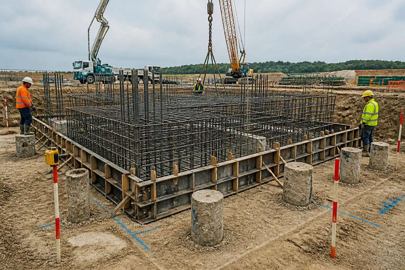
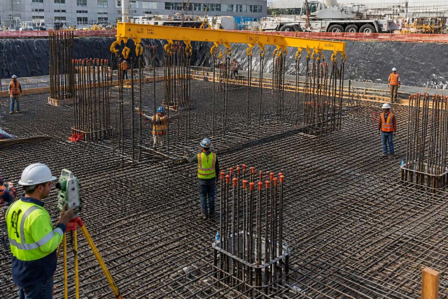
| 1 | Setting Out and Base Check | Survey and mark grid lines, column/pile centerlines, and reference levels on blinding or pile cap surface. Verify dimensions against IFC and tolerances. | Surveyor/Site Engineer | Check against benchmarks |
| 2 | Material Receipt, Sorting, and Storage | Receive marked bar bundles with heat numbers; sort by BBS marks near workface on timber dunnage; protect from contamination and standing water. | Storekeeper/QA-QC | Visual; document check |
| 3 | Install Spacers and Side Cover Controls | Fix concrete spacers at base and edges at calculated spacing. For raft base, use 75 mm spacers typically [Verify]. | Rebar Supervisor | Visual/measure |
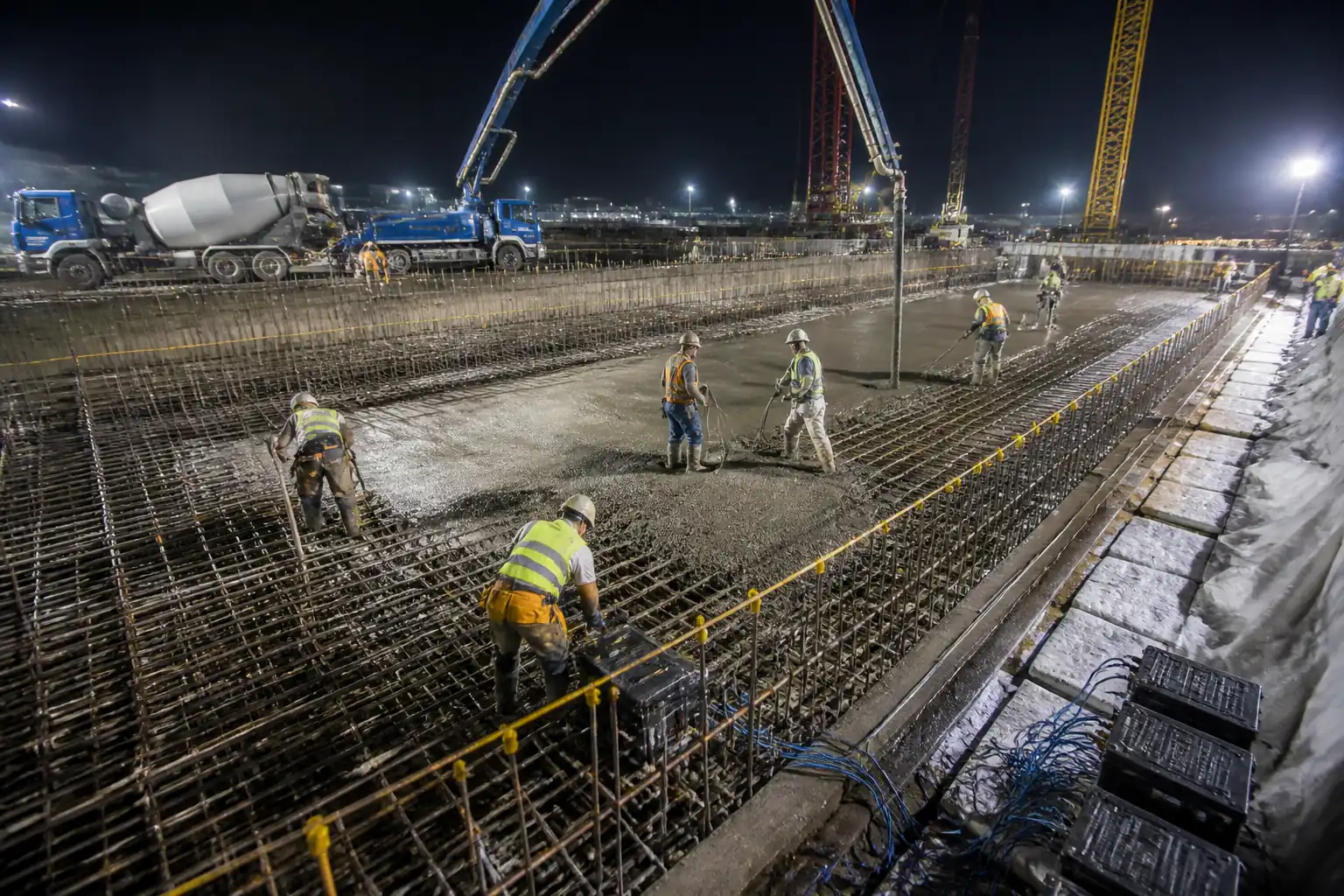
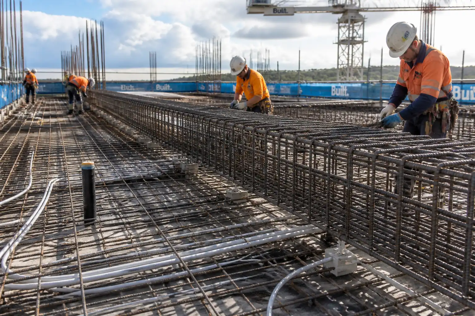
| 4 | Bottom Mat Placement | Lay bottom layer longitudinal bars first, then transverse bars per BBS. Use string lines and spacers to maintain spacing. Tie perimeter at every intersection and internal at alternate intersections (staggered) unless otherwise specified. | Rebar Supervisor | Dimensional check |
| 5 | Fix Shear/Distribution Reinforcement | Install links/stirrups, additional bars over piles/columns, and trimming bars around openings as per details. Maintain required hook bends and anchorage. | Rebar Supervisor | Visual; measurement |
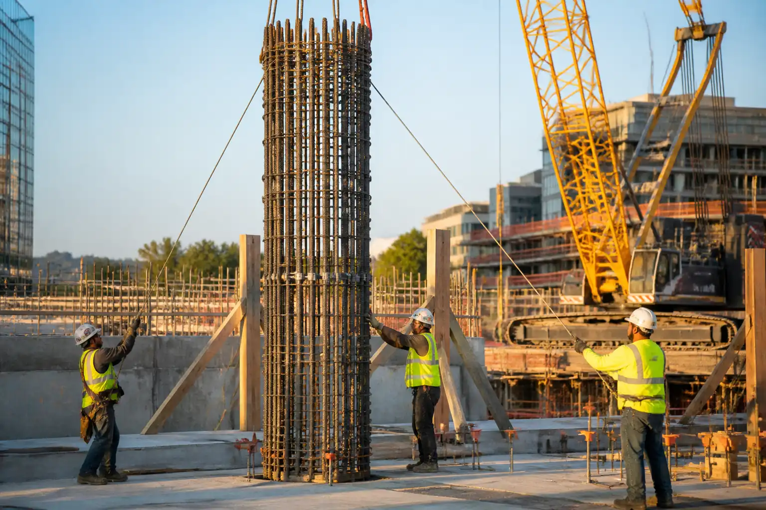
| 6 | Column/Pier Starter Bars and Templates | Install starter bars using rigid steel/ply templates referenced to survey marks. If couplers used, ensure thread protection caps removed only at assembly. Provide sleeves/box-outs where later adjustment is required. | Site Engineer/Surveyor | Survey witness |
| 7 | Lap Splices/Mechanical Splices | Execute laps as per IFC; stagger laps where required. For couplers, clean threads, apply lubricant (if specified), and tighten to manufacturer torque; check with go/no-go gauge when applicable. | Rebar Supervisor/QA-QC | Hold/Witness as per ITP |
| 8 | Top Mat Chairs/High Supports Installation | Install heavy-duty chairs with corrosion-protected tips at calculated spacing/rows to support top mat at design elevation. Provide walkboards to distribute loads. | Rebar Supervisor | Visual/measurement |
| 9 | Top Mat Placement and Tying | Lay top mat per BBS; tie perimeter at every intersection and internal at alternate intersections or as specified. Maintain clearances to sleeves/openings. | Rebar Supervisor | Dimensional check |
| 10 | Interface Coordination (MEP/Embedded Items) | Install and secure sleeves, puddle flanges, earthing bars, and embeds coordinated with trades. Maintain reinforcement continuity and provide trimmers as detailed. | Site Engineer/MEP Coord. | Joint inspection |
| 11 | Housekeeping and Access Control | Fit safety caps to protruding bars at walkways; install temporary walkboards; remove loose wire ends; clear debris within reinforcement zone. | Foreman/HSE | HSE inspection |
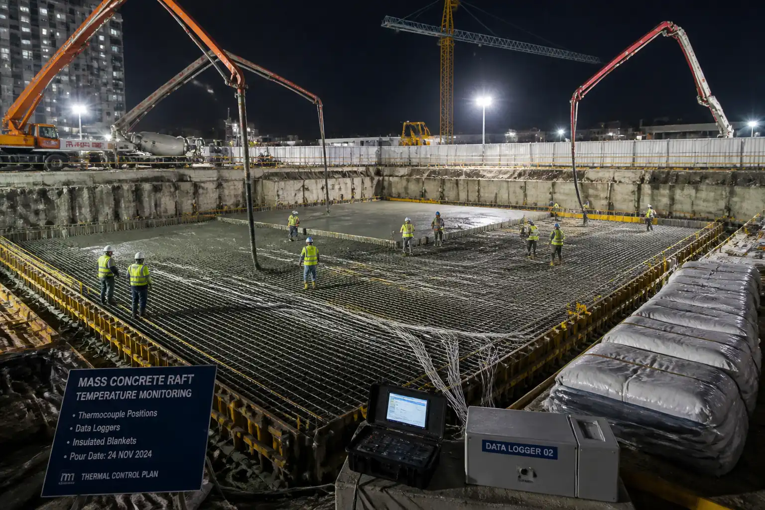
| 12 | Pre-Pour Inspection (HOLD POINT) | Raise Inspection Request (IR). QC performs internal check before Consultant hold point. Provide as-built markups, measurements, and records for review. | QA/QC Engineer | HOLD—Consultant |
| 13 | Final Pour Readiness | Install final top cover blocks where removable supports used; confirm pour sequence, pump lines, and vibrator access do not displace reinforcement; protect template/threads. | Construction Manager | Pre-pour walkdown |
Health, Safety, and Environment (HSE) - Safety Controls
Task-Specific Hazards and Controls
1) Hazard: Crane and rigging operations with heavy rebar bundles
- Likely consequence: Crushing, struck-by, dropped load, rig collapse
- Engineering/procedural control: Lift plan and rigging study; certified crane/operator; use of spreader beam to control sling angles ≤60°; tag lines; exclusion zones with barriers; no personnel under suspended loads; weather/wind limits [Verify per HSE plan].
- Required PPE: Helmet with chin strap, gloves (cut-resistant), safety boots, high-vis, eye protection
- Collective preventive measure: Physical barriers and banksman control; radio comms
- Inspection/permit/supervision: Lifting permit; pre-use checks; daily crane/rigging inspection; competent lifting supervisor present
2) Hazard: Impalement and trips on protruding bars
- Likely consequence: Puncture injuries, falls
- Engineering/procedural control: Fit rebar safety caps on exposed bars at access routes; designate walkways; trim or bend tie-wire tails inward
- Required PPE: Helmet, gloves, boots, long sleeves
- Collective preventive measure: Edge protection and marked walkways
- Inspection/permit/supervision: Daily HSE walkdowns; housekeeping checklist
3) Hazard: Manual handling of heavy bars and top-mat works at height over congested reinforcement
- Likely consequence: Musculoskeletal injury, slips/falls
- Engineering/procedural control: Team lifts with proper technique; use mechanical aids (gin wheels, mini-cranes); install secured walkboards/platforms; restrict carrying across unsupported mats
- Required PPE: Anti-slip safety boots, gloves, helmet
- Collective preventive measure: Temporary platforms with guardrails where practicable
- Inspection/permit/supervision: Work at Height assessment; scaffold/waH inspection tags
4) Hazard: Cutting/grinding of bars (where permitted)
- Likely consequence: Eye injuries, sparks/fire, noise
- Engineering/procedural control: Pre-approval and Hot Works Permit; spark containment; fire watch; correct discs/guards; local fume extraction in confined areas
- Required PPE: Face shield/eye protection, hearing protection, gloves, FR clothing as needed
- Collective preventive measure: Fire extinguishers, welding blankets
- Inspection/permit/supervision: Hot Works Permit; gas test if confined; extinguisher checks
5) Hazard: Working in deep excavations around pile caps/rafts
- Likely consequence: Falls, entrapment, inundation
- Engineering/procedural control: Access ladders/stairs; edge protection; dewatering maintained; emergency egress; geotechnical monitoring where specified
- Required PPE: Helmet, boots, high-vis, headlamp for low light
- Collective preventive measure: Barriers and signage; rescue plan
- Inspection/permit/supervision: Excavation permit; daily inspection by competent person; dewatering checks
6) Hazard: Noise and vibration from tools/crane
- Likely consequence: Hearing loss, hand-arm vibration syndrome
- Engineering/procedural control: Selection of low-noise tools; limit exposure durations; maintenance of tools
- Required PPE: Hearing protection
- Collective preventive measure: Zoning and scheduling noisy tasks
- Inspection/permit/supervision: Noise monitoring where required
7) Hazard: Unauthorized modification of reinforcement (cutting main bars for clashes)
- Likely consequence: Structural non-conformance, failure
- Engineering/procedural control: Strict prohibition; use RFIs for coordination; provide trimmer bars per engineer’s instruction
- Required PPE: Standard PPE for inspection
- Collective preventive measure: Supervision and signage at workface
- Inspection/permit/supervision: QC hold/witness points; engineer approval required
[Verify additional statutory requirements per project HSE plan and local regulations].
Environmental Controls
- Steel Waste Management: Segregate offcuts by size; return usable lengths to stock; scrap to licensed recycler. Record weights for diversion reporting.
- Noise and Light: Restrict high-noise and night lighting to permitted hours; use directional/task lighting; maintain equipment to reduce noise.
- Dust and Debris: Wet suppression for cutting/grinding; collect metal swarf; prevent debris falling into drainage sumps.
- Water Protection: Prevent oils/lubricants (from couplers/tools) from entering stormwater; drip trays under stationary equipment; spill kits at point-of-use.
- Energy/Emissions: Plan deliveries to minimize idling; switch off unused plant; use electric tying tools where practical.
- Resource Efficiency: Use proprietary continuous bar supports to reduce number of chairs; optimize bar cuts per BBS to limit waste.
- Compliance: Maintain environmental permits, conduct toolbox briefings on spill response, and log incidents per ISO 14001.
Quality Assurance / Quality Control
Controls and Records
- Material Verification: MIR approval; mill/test certificates check for grade, ductility, yield/UTS, bend tests per ASTM A615/A706 or BS 4449. Sampling frequency typically 1 set per heat per 25 t [Verify per spec].
- BBS/IFC Conformance: Random dimensional checks against BBS; mark-up drawings at site for any approved deviations; maintain bar mark traceability.
- Cover and Spacing Control: Pre-pour measurement using rulers/feeler gauges and templated spacers. Acceptance: minimum cover ≥ specified; bar spacing within ±10 mm [Verify]; top mat level −0/+10 mm.
- Lap/Splice Verification: Measure lap lengths; stagger as detailed; verify coupler engagement/torque per manufacturer; review ISO 15835 batch test certificates.
- Starter Bar Alignment: Survey check of position and verticality; template records with as-built coordinates.
- Workmanship: Cleanliness (no loose rust, mud, oil) per ACI 301; no rebar heating; bends free of cracks; damaged epoxy coating (if any) repaired per manufacturer.
- Nonconformance: Raise NCR for deviations; engineer-approved remedial actions; record re-inspections.
- Hold/Witness: Implement ITP with hold for pre-pour; witness for couplers; surveillance during fixing.
- Records: MIRs, delivery notes, calibration certificates, torque logs, inspection checklists, IR approvals, as-built photos, RFI/NCR logs.
- Post-Pour Verification: Where specified, perform random cover survey with cover meter after concrete hardening; acceptance per governing code [Verify per project].
Attachments
- Sample Rebar Pre-Pour Checklist (cover, spacing, laps, couplers, starter bar alignment, embeds, cleanliness)
- Typical Lift Plan extract for rebar bundles/cages
- Manufacturer Datasheets: couplers, spacers/chairs
- Calibration certificates: survey instruments, torque wrenches
- Example Torque Log Sheet for couplers
- Example As-Built Survey Template for starter bars
- Permits: Lifting, Hot Works, Work at Height, Excavation (as applicable)
- RFI/NCR log excerpts for coordination and closures
This content is a read-only public reference. Download or customize to get an editable version.
ITP preview
The first inspection activities from the linked ITP for Method Statement: Installation of Heavy Steel Reinforcement for Thick Raft Foundations and Pile Caps:
| Activity | Inspection / Test | Acceptance Criteria | Responsibility | Record |
|---|---|---|---|---|
| Material receipt of reinforcement and accessories | Verify grade, size, heat, certificates | Conforms to MIR, standards (ASTM A615/A706 or BS 4449), no damage/corrosion beyond light surface rust; traceability intact | Contractor QC (Perform), Consultant (Review) | MIR, delivery notes, mill certs |
| Storage and handling | Elevation off ground, segregation by mark | Off-ground on dunnage; protected from contamination; no ponding water | Contractor QC/Site | Checklist, photos |
| Setting out and base preparation | Line/level verification | Grid/levels within ±10 mm [Verify]; base clean and sound | Surveyor/Site Engineer | Survey report |
Showing 3 of 11 inspection activities. View full ITP →
Related Inspection and Test Plan
An Inspection and Test Plan (ITP) is available for Method Statement: Installation of Heavy Steel Reinforcement for Thick Raft Foundations and Pile Caps. The ITP defines the inspection activities, acceptance criteria, hold and witness points, responsible parties, and records required to verify the work described in this method statement.
View the Method Statement: Installation of Heavy Steel Reinforcement for Thick Raft Foundations and Pile Caps ITP →Frequently asked questions
Continue with related Quollnet resources connected to this method statement.