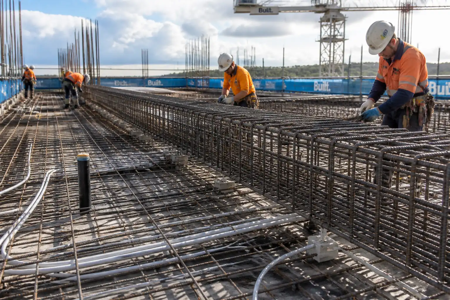
Method Statement: Fixing and Tying of Vertical Reinforcement Cages for Structural Columns and Shear Walls – Method Statement
AI-assisted method statement with matching ITP, PDF download, and Excel export.
More than a static template
Unlike a downloadable Word or PDF template, this method statement is an AI-assisted editable starting point connected directly to a matching Inspection and Test Plan. Every section is structured, project-adaptable, and ready to export.
- AI-assisted drafting — Customize every section with AI for your specific project scope.
- Linked ITP — A matching inspection and test plan is generated alongside the method statement.
- Multiple export formats — Download as a formatted PDF or editable Excel spreadsheet.
- Editable starting point, not a final document — Review, verify, and adjust all content against your project requirements before use.
Static template vs. Quollnet workflow
| Feature | Static template | Quollnet |
|---|---|---|
| Project-specific content | Manual fill-in required | AI-assisted customization |
| Linked ITP | Separate document, no link | Matching ITP included |
| Export formats | Usually PDF only | PDF and Excel |
| Structured sections | Free-form layout | 13 standardized sections |
| Saved to your account | Local file only | Cloud-saved, reusable |
| Content accuracy | You verify everything | AI-assisted, you still verify |
| Cost | Often free but time-intensive | Free to customize and download |
What you can customize
When you save this method statement to your account, every section becomes editable. The following 13 sections are included:
- Scope — Defines the activity and its boundaries.
- References — Standards, specifications, and drawings.
- Responsibilities — Roles and accountabilities.
- Resources — Labour, plant, and equipment summary.
- Materials — Materials and compliance requirements.
- Equipment — Tools and equipment details.
- Prerequisites — Hold points and pre-conditions.
- Method sequence — Step-by-step construction sequence.
- Safety controls — HSE risk controls and PPE.
- Environmental controls — Environmental mitigation measures.
- QA/QC — Quality inspection and test requirements.
- ITP — Inspection and Test Plan table (has its own page).
- Attachments — Referenced drawings and documentation.
Why this method statement is used
This method statement is used to define and communicate the approved procedure for carrying out method statement: fixing and tying of vertical reinforcement cages for structural columns and shear walls on site. It ensures the work is planned in advance, the correct resources and controls are in place, and all personnel understand responsibilities, sequence, quality requirements, and safety controls before work begins. It aligns site execution with the documented scope and acceptance expectations.
Who uses this method statement
This method statement is used by contractors, site supervisors, project engineers, QA/QC engineers, HSE officers, consultants, and client representatives. It serves as a shared reference for planning, execution, supervision, inspection, and approval of the activity on site.
When it is prepared and submitted
The method statement is prepared before the work activity starts and submitted as part of the pre-construction documentation package for review and approval.
Who reviews or approves it
The method statement is usually submitted to the client representative, consultant, resident engineer, or project management consultant for review and approval before the work commences.
Important approval note
This method statement is an AI-assisted editable starting point, not a pre-approved document. Before use on any project, all content must be reviewed and approved by the relevant parties (superintendent, principal contractor, or client representative) in accordance with your contract and project quality plan.
For example: if your specification requires a departure from a referenced standard, that departure must be documented and approved separately — this method statement will not capture that automatically. Always verify against your applicable drawings, specifications, and regulatory requirements.
Method statement content
Scope
Description
This method statement covers supply to workface, fixing, tying, and quality control of vertical reinforcement cages for in-situ reinforced concrete columns and shear walls, including:
- Verification of rebar diameter, grade, heat numbers, and bar bending schedules (BBS).
- Lap length checks and installation of mechanical splices (couplers) where specified.
- Installation of confinement ties/links and cross-ties, including spacing, hooks, and seismic detailing where applicable.
- Provision of concrete cover using compliant spacers/blocks and retainers.
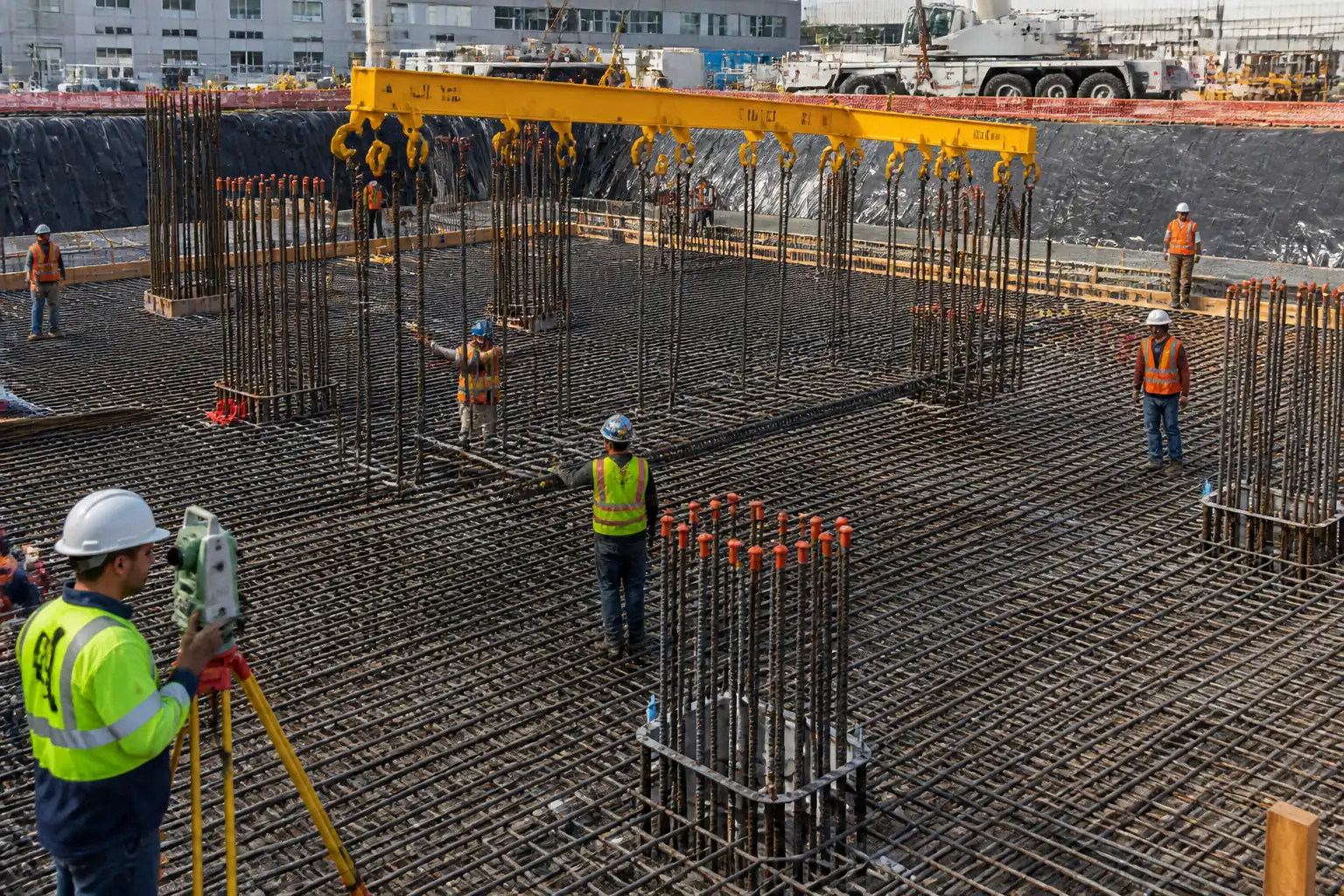
- Cage lifting/erection, temporary stability bracing, alignment, and positional control within formwork or guides.
- Interfaces with starter bars, dowels, embeds, and continuity reinforcement.
- Pre-pour inspections and records prior to concrete placement (concrete placement by separate method statement).
Exclusions
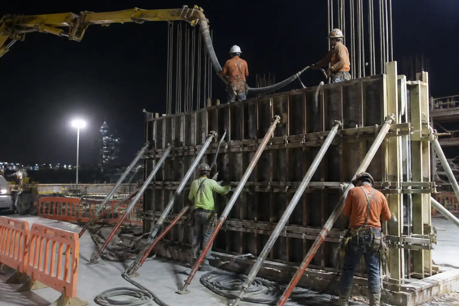
- Concrete placement, vibration, and curing.
- Permanent formwork installation (addressed in dedicated formwork method statement).
- Welding to reinforcement (prohibited unless specifically approved per project specifications).
References
| Document Type | Reference / Number | Revision | Notes |
|---|---|---|---|
| Standard | ACI 318 | ||
| Standard | ACI 117 | ||
| Standard | ACI 301 | ||
| Standard | BS EN 1992-1-1 | Use if project is Eurocode-based [Verify] | |
| Standard | BS 8666 | For BBS format and bending radii [Verify] | |
| Standard | ISO 15835 | If ISO-based coupler qualification is required [Verify] | |
| Standard | ASTM A615/A706 | Material grade verification [Verify] | |
| Contract | Project Specs/IFC | Engineer’s instructions prevail |
Responsibilities
| Role | Responsibility | Name / Party |
|---|---|---|
| PM | Approve method, ensure resources and programme | Contractor |
| CM/SE | Ensure sequence, tolerances, and safety controls implemented | Contractor |
| Foreman | Self-checks, rectify nonconformities | Contractor |
| Surveyor | Provide as-set-out sketches | Contractor |
| QA/QC | Witness/verify laps, couplers, spacing, cover, verticality, bracing | Contractor |
| HSEO | Toolbox talks, inspections, stop-work authority | Contractor |
| LIFT SUP | Rigging plan, load charts, exclusion zones | Contractor |
| Engineer | RFI response and NCR disposition | Engineer |
Resources
| Resource Type | Description | Quantity | Remarks |
|---|---|---|---|
| Manpower | Tying, spacing, coupler installation | As scheduled | |
| Manpower | Material handling, spacer distribution, housekeeping | As required | |
| Manpower | Install and verify mechanical splices per manufacturer | 1 per active front | |
| Manpower | Install work platforms for upper lifts | As required |
Materials
| Material | Specification / Grade | Quantity | Remarks |
|---|---|---|---|
| Rebar | As per BBS | ||
| Couplers | As per shop drawings | ||
| Tie wire | ~2–3 kg/ton rebar [Verify] | ||
| Spacers | As required | ||
| Coatings |
Equipment
| Equipment | Capacity / Type | Quantity | Inspection Required |
|---|---|---|---|
| Bender/Shear | Up to max bar size | As needed | |
| Torque wrench | Up to required torque | 1 per crew | |
| Crane/Rigging | Per lift study | As planned | |
| Bracing | Design per calc | As required | |
| Scaffolds/Ladders | As required | ||
| Survey tools | Set per crew |
Prerequisites
- Approved IFC drawings, bar bending schedules (BBS), and shop drawings for columns/walls.
- Approved product data for reinforcement, couplers, and spacers; MIRs and mill certificates available.
- Method statement and ITP approved by Engineer.
- PTW/permit to work issued for lifting and working at height [Verify per project HSE plan and local regulations].
- Survey control established: gridlines, element centrelines, and reference levels transferred and protected.
- Formwork reference lines and alignment guides marked; embed/insert coordination completed.
- Valid calibration certificates for torque wrenches, bending equipment, and survey devices.
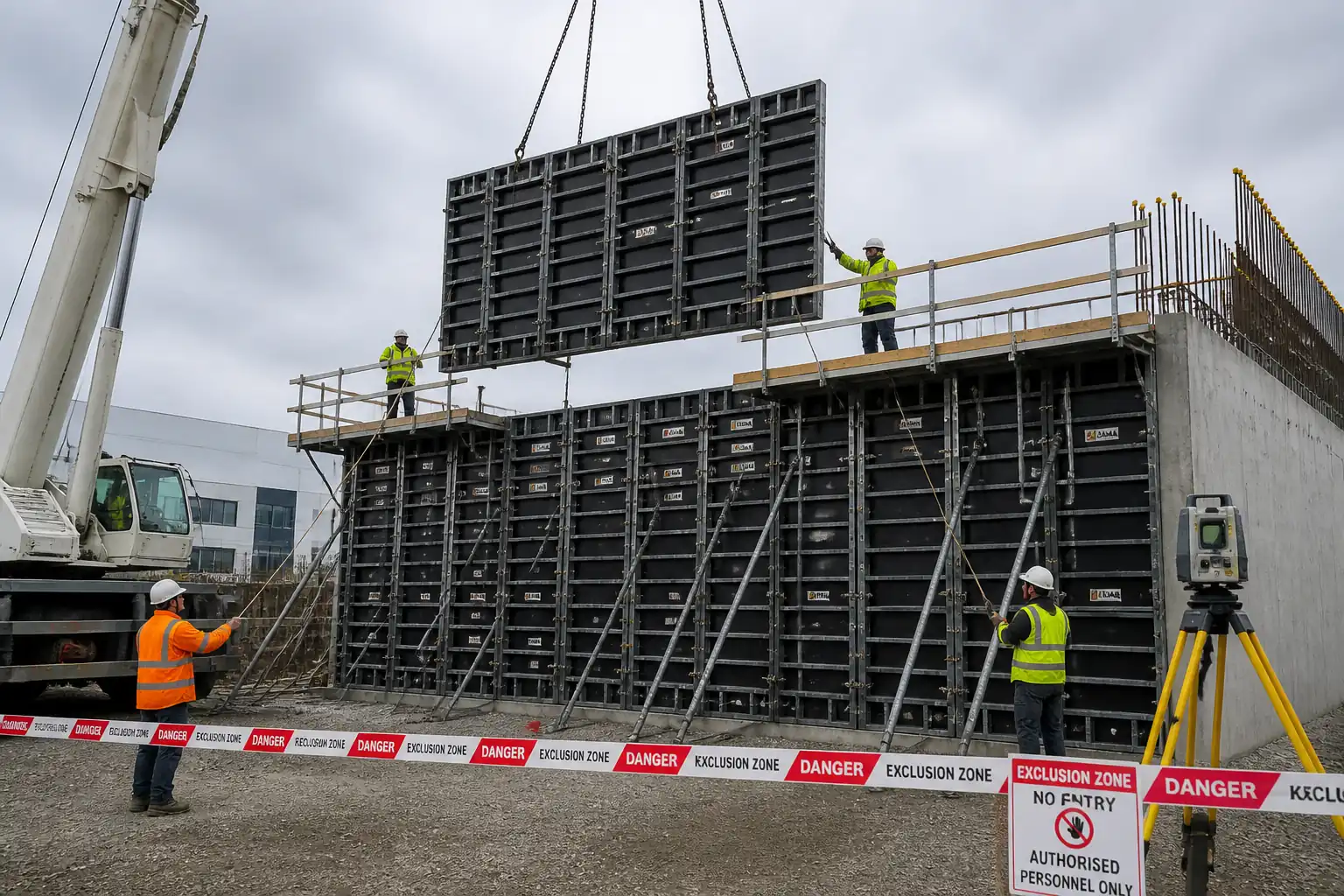
- Lifting plan and rigging gear certified; exclusion zones planned and barricaded.
- JSA/Task risk assessment and toolbox talk completed with crew sign-on.
- Storage area prepared: off-ground timber dunnage, weather protection, and segregation by bar size/heat number.
- Access arrangements and lighting suitable for tying and inspection.
- If seismic or boundary element details apply, latest revision and special detailing notes briefed to team.
Method Sequence
| Step | Activity | Description | Responsibility | Inspection / Hold Point |
|---|---|---|---|---|
| 1 | Receipt, identification, and storage of reinforcement | Receive bars with delivery dockets and MTCs; segregate by diameter/heat. Store on dunnage ≥100 mm above ground; cover to prevent contamination. Inspect for rust, oil, or deformation. | Rebar Foreman / QA/QC | Material receiving inspection |
| 2 | Verification of BBS and site dimensions | Confirm BBS against IFC drawings; verify element sizes, cover requirements, lap locations, coupler positions, and starter bars at interface. | Site Engineer | Document check and site measure |
| 3 | Cutting and bending (if done on site) | Perform cutting/bending per BS 8666 shapes and radii; avoid re-bending unless approved. Deburr cut ends where couplers to be installed. | Rebar Foreman | Process control inspection |
| 4 | Pre-assembly of cages (ground level where feasible) | Lay out longitudinal bars on assembly jig/spacers; install first tier of ties/links at specified spacing; maintain geometry using templates/strongbacks. | Rebar Foreman | Self-check with supervision |
| 5 | Lap length or mechanical splice preparation | Locate splice zones per drawings; for lap splices, stagger laps as specified; for couplers, clean bar threads/ends, trial fit, and mark engagement length. | Coupler Technician / Rebar Foreman | Hold/ Witness as per ITP |
| 6 | Installation of confinement ties/links and cross-ties | Fix ties at specified spacing; provide 135° hooks with 10 db extension where seismic or ductile detailing required [Verify]; ensure alternating cross-ties to restrain every bar. | Rebar Foreman / Site Engineer | Dimensional check |
| 7 | Cover blocks/spacers installation | Install approved spacers sized to nominal cover on all faces; fix with tie wire. Increase frequency at corners/edges and near laps/couplers. | Rebar Foreman | Cover check |
| 8 | Cage lifting and erection into position | Rig cage using certified slings/spreader to prevent distortion; lift per plan; position over starters/dowels; install temporary supports, strongbacks and base clamps. | Lifting Supervisor / Site Engineer | Lift execution supervision |
| 9 | Stability bracing and alignment | Install designed temporary bracing (kickers, props, guys) anchored to stable points. Align cage to survey marks; restrain at base and top. Protect from wind and impact. | Site Engineer / Foreman | Plumb and brace check |
| 10 | Coupler final installation and lap verification in-situ | Complete torqueing of couplers at height as required; re-check lap/splice zones in final position; ensure stagger and confinement maintained. | Coupler Technician / QA/QC | Witness as per ITP |
| 11 | Integration with embeds and penetrations | Adjust bars locally per approved details to clear sleeves/inserts; do not cut bars without approval; provide additional bars if required by approved sketch. | Site Engineer | Field change control |
| 12 | Pre-pour inspection and release | Comprehensive check for bar size/count, spacing, laps/couplers, cover, alignment, cleanliness, and bracing; submit RFI for Engineer’s inspection. | QA/QC Engineer | Hold point—Engineer inspection |
Health, Safety, and Environment (HSE) – Task-Specific Safety Controls
Key Hazards, Consequences, Controls, PPE, and Requirements
1) Hazard: Struck-by or crush during lifting/erection of cages
- Likely consequence: Serious injury/fatality from dropped/ swinging load
- Engineering/procedural control: Engineered lift plan; certified rigging; taglines; exclusion zone; weather limits (suspend lifts above safe wind threshold [Verify per site policy, typically 9–12 m/s])
- Required PPE: Hard hat with chin strap, gloves, safety boots, high-vis, eye protection
- Collective preventive measure: Barriers and banksman control; radio communication; no access under suspended load
- Inspection/permit/supervision: Pre-lift inspection checklist; Lifting Supervisor in control; valid PTW for lifting
2) Hazard: Cage instability/topple before concreting
- Likely consequence: Collapse causing crush injuries and damage
- Control: Temporary bracing designed/checked by Site Engineer; base clamps; guying; routine re-check after wind or impact
- PPE: As above
- Collective measure: Physical bracing, secured anchors, exclusion zone maintained
- Requirement: Daily brace inspection and after adverse weather; recorded on brace checklist
3) Hazard: Falls from height while tying upper lifts
- Likely consequence: Major injury/fatality
- Control: Provide working platforms/scaffold with guardrails; fall arrest only if collective protection not feasible; maintain three points of contact on ladders (work from ladder prohibited for tying beyond brief access [Verify])
- PPE: Full-body harness with double lanyard if fall arrest used
- Collective measure: Mobile towers/podiums, edge protection
- Requirement: Scaffolds tagged after inspection; PTW for work at height
4) Hazard: Rebar impalement and lacerations
- Likely consequence: Puncture wounds, severe injury
- Control: Cap all protruding bars with approved mushroom caps or timber troughs; maintain housekeeping and clear walkways
- PPE: Cut-resistant gloves, long sleeves
- Collective measure: Impalement protection caps/barriers
- Requirement: Daily HSE inspection; immediate replacement of missing caps
5) Hazard: Manual handling and repetitive strain (tying, carrying bars)
- Likely consequence: Musculoskeletal injuries
- Control: Team lifts; mechanical aids; rotate tasks; use tying guns where practicable
- PPE: Back support as required, gloves
- Collective measure: Work sequencing to minimize handling, pre-assembly at ground
- Requirement: Manual handling training; supervision spot checks
6) Hazard: Pinch/hand injuries during coupler torqueing
- Likely consequence: Finger crush/abrasion
- Control: Use torque wrench with proper stance; keep hands clear; use knuckle guards
- PPE: Impact-resistant gloves, eye protection
- Collective measure: Task-specific training by manufacturer
- Requirement: Tool inspection; torque range calibrated
7) Hazard: Noise and vibration from cutting/bending tools
- Likely consequence: Hearing damage
- Control: Use low-noise equipment; time limits; acoustic screens if needed
- PPE: Hearing protection
- Collective measure: Noise mapping and signage
- Requirement: Periodic noise surveys [Verify per project HSE plan]
8) Hazard: Interaction with existing live utilities (in retrofit areas)
- Likely consequence: Electrocution, service damage
- Control: Permit to dig/penetrate; cable/pipe scan; isolation and lockout where relevant
- PPE: Insulated gloves where applicable, dielectric boots
- Collective measure: Marked services, no-go zones
- Requirement: Approved PTW; supervision during works
9) Hazard: Hot works (only if exceptional welding on rebar is approved)
- Likely consequence: Fire, fume inhalation
- Control: Hot work permit; ISO 17660-qualified welding procedure and welder; fire watch; ventilation
- PPE: Welding PPE per WPS
- Collective measure: Fire blankets, extinguishers
- Requirement: Hot work permit and WPS/PQR approval [Verify]
[Verify per project HSE plan and local regulations] for any additional legal or project-specific requirements.
Environmental Controls
- Steel and tie-wire waste: Segregate and send to licensed recycler; collect tie-wire offcuts in bins at workface.
- Oils/grease from equipment: Store spill kits at lifting and assembly zones; drip trays under hydraulic tools; immediate spill containment and report.
- Noise: Schedule high-noise cutting/bending to daytime; use acoustic barriers near sensitive receptors; monitor if required by permit.
- Dust/particulates: Minimize dry cutting; wet wipe bars if dusty; maintain housekeeping; no abrasive blasting without permit.
- Visual and site tidiness: Stack bars on dunnage; maintain clear walkways; remove protruding offcuts promptly.
- Waterways/drain protection: Keep work away from drains; fit silt socks; no washout into stormwater.
- Material provenance: Retain mill certs to demonstrate responsible sourcing if required (e.g., BES 6001 equivalent) [Verify].
- End-of-shift: Remove loose wires, empty bins, secure cages against wind, and close exclusion zones.
Quality Assurance and Quality Control
Controls and Records
- Material verification: MIR with mill certificates for each heat/lot; coupler product approvals; torque wrench calibration.
- In-process checks: Bar diameter/count; tie spacing; hook geometry; lap/mechanical splice details; cover blocks type and spacing.
- Survey/positioning: Verify centreline and cover using control lines; record plumb and positional offsets.
- Tolerances (typical—verify per project/ACI 117/EC2):
- Reinforcement position: ±10 mm typical for columns/walls [Verify].
- Lap lengths: Not less than code/drawing minimum; measure actual and record.
- Tie spacing: Within ±10 mm of specified; not exceeding code maximums.
- Verticality (cage plumb): ≤ H/1000 or 10 mm, whichever greater [Verify].
- Cover: Achieve c_nom; for EC2, Δc_dev typically 10 mm; for ACI, negative tolerance not permitted beyond specified cover [Verify].
- Hold/Witness points: As defined in ITP for material receiving, splice verification, pre-pour.
- Nonconformance: Raise NCR for deviations; propose disposition; implement corrective action and re-inspect.
- Records: Checklists, photos, torque logs, IRs/RFIs, as-built sketches.
- Training/qualification: Coupler installers trained by manufacturer; fixers briefed on seismic/boundary details where relevant.
Attachments
- Sample Pre-Pour Rebar Inspection Checklist (columns/walls)
- Example Bracing/Strongback Sketch for Typical Column Cage
- Manufacturer’s Mechanical Coupler Installation Guide and Torque Table
- Bar Bending Schedule (BBS) Template per BS 8666
- Lift Plan Template for Rebar Cage Erection
- Toolbox Talk: Rebar Impalement and Lifting Hazards
- Calibration Certificates (Torque Wrench, Measuring Devices)
This content is a read-only public reference. Download or customize to get an editable version.
ITP preview
The first inspection activities from the linked ITP for Method Statement: Fixing and Tying of Vertical Reinforcement Cages for Structural Columns and Shear Walls:
| Activity | Inspection / Test | Acceptance Criteria | Responsibility | Record |
|---|---|---|---|---|
| Material receiving – rebar and accessories | Verify grade, diameter, heat numbers; review MTCs and compliance | Materials comply with ASTM A615/A706 or BS 4449; certificates approved; no damage/contamination | QA/QC Engineer (Contractor) / Witness: Engineer | MIR; Material inspection checklist |
| Couplers – product verification | Check coupler type/class against drawings; verify lot/batch certs | Qualified to ISO 15835 or ACI Type 2 as specified; size and thread match bars | QA/QC Engineer / Witness: Engineer | MIR; Product approvals |
| Cutting/bending inspection (if on site) | Measure lengths/angles; inspect bend radius and bar condition | Dimensional tolerance per BS 8666; no cracks or re-bend without approval | QA/QC Engineer | In-process QC log; photos |
Showing 3 of 10 inspection activities. View full ITP →
Related Inspection and Test Plan
An Inspection and Test Plan (ITP) is available for Method Statement: Fixing and Tying of Vertical Reinforcement Cages for Structural Columns and Shear Walls. The ITP defines the inspection activities, acceptance criteria, hold and witness points, responsible parties, and records required to verify the work described in this method statement.
View the Method Statement: Fixing and Tying of Vertical Reinforcement Cages for Structural Columns and Shear Walls ITP →Frequently asked questions
Continue with related Quollnet resources connected to this method statement.