Method Statement: Installation of PVC and Hydrophilic Swellable Waterstops in Concrete Construction and Expansion Joints – Method Statement
AI-assisted method statement with matching ITP, PDF download, and Excel export.
More than a static template
Unlike a downloadable Word or PDF template, this method statement is an AI-assisted editable starting point connected directly to a matching Inspection and Test Plan. Every section is structured, project-adaptable, and ready to export.
- AI-assisted drafting — Customize every section with AI for your specific project scope.
- Linked ITP — A matching inspection and test plan is generated alongside the method statement.
- Multiple export formats — Download as a formatted PDF or editable Excel spreadsheet.
- Editable starting point, not a final document — Review, verify, and adjust all content against your project requirements before use.
Static template vs. Quollnet workflow
| Feature | Static template | Quollnet |
|---|---|---|
| Project-specific content | Manual fill-in required | AI-assisted customization |
| Linked ITP | Separate document, no link | Matching ITP included |
| Export formats | Usually PDF only | PDF and Excel |
| Structured sections | Free-form layout | 13 standardized sections |
| Saved to your account | Local file only | Cloud-saved, reusable |
| Content accuracy | You verify everything | AI-assisted, you still verify |
| Cost | Often free but time-intensive | Free to customize and download |
What you can customize
When you save this method statement to your account, every section becomes editable. The following 13 sections are included:
- Scope — Defines the activity and its boundaries.
- References — Standards, specifications, and drawings.
- Responsibilities — Roles and accountabilities.
- Resources — Labour, plant, and equipment summary.
- Materials — Materials and compliance requirements.
- Equipment — Tools and equipment details.
- Prerequisites — Hold points and pre-conditions.
- Method sequence — Step-by-step construction sequence.
- Safety controls — HSE risk controls and PPE.
- Environmental controls — Environmental mitigation measures.
- QA/QC — Quality inspection and test requirements.
- ITP — Inspection and Test Plan table (has its own page).
- Attachments — Referenced drawings and documentation.
Why this method statement is used
This method statement is used to define and communicate the approved procedure for carrying out method statement: installation of pvc and hydrophilic swellable waterstops in concrete construction and expansion joints on site. It ensures the work is planned in advance, the correct resources and controls are in place, and all personnel understand responsibilities, sequence, quality requirements, and safety controls before work begins. It aligns site execution with the documented scope and acceptance expectations.
Who uses this method statement
This method statement is used by contractors, site supervisors, project engineers, QA/QC engineers, HSE officers, consultants, and client representatives. It serves as a shared reference for planning, execution, supervision, inspection, and approval of the activity on site.
When it is prepared and submitted
The method statement is prepared before the work activity starts and submitted as part of the pre-construction documentation package for review and approval.
Who reviews or approves it
The method statement is usually submitted to the client representative, consultant, resident engineer, or project management consultant for review and approval before the work commences.
Important approval note
This method statement is an AI-assisted editable starting point, not a pre-approved document. Before use on any project, all content must be reviewed and approved by the relevant parties (superintendent, principal contractor, or client representative) in accordance with your contract and project quality plan.
For example: if your specification requires a departure from a referenced standard, that departure must be documented and approved separately — this method statement will not capture that automatically. Always verify against your applicable drawings, specifications, and regulatory requirements.
Method statement content
Scope
Work Included
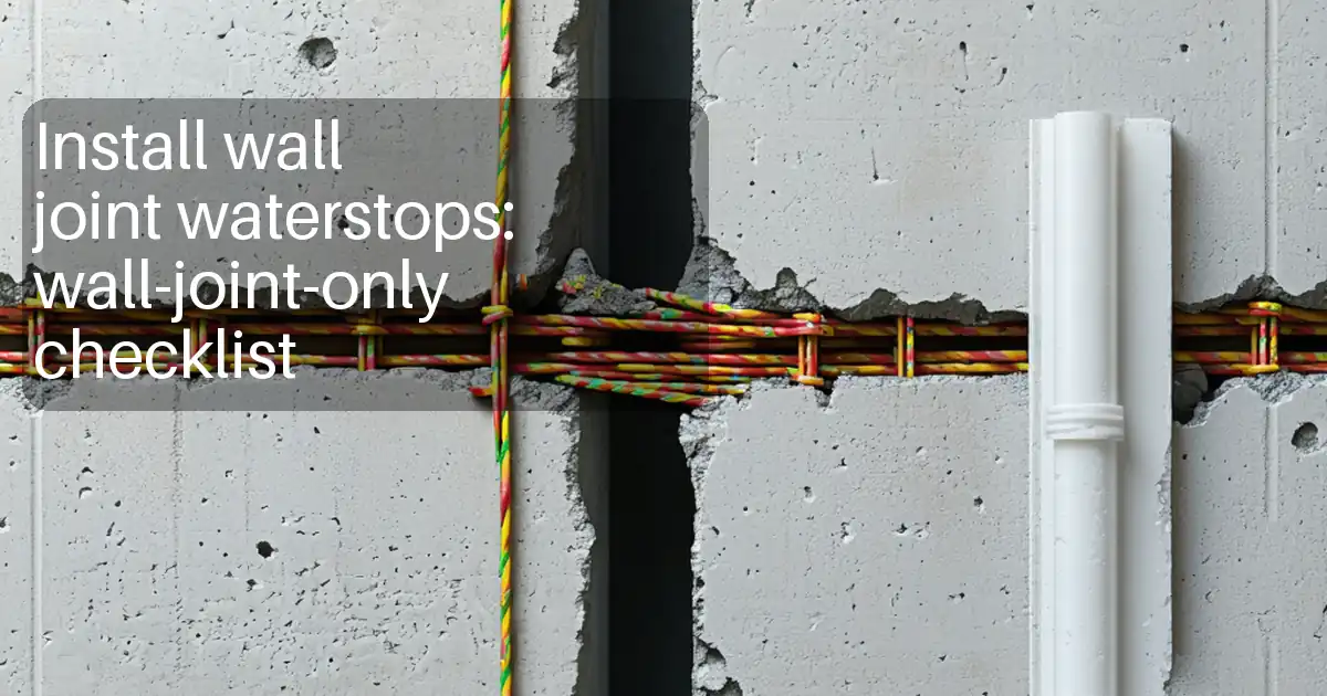
- Supply, storage, handling, and installation of PVC waterstops (centerbulb expansion, ribbed/flat construction joint types) and hydrophilic swellable waterstops/strips at all specified joints, kickers, and penetrations.
- On-site thermoplastic splicing/welding of PVC waterstops including straight butt, T-, L-, and X- configurations using jigs and controlled heating tools.
- Mechanical fastening of waterstops to reinforcement/formwork to maintain alignment and embedment during concreting.
- Surface preparation and priming (as required by manufacturer) and installation of hydrophilic strips including corners and transitions, and protection prior to pour.
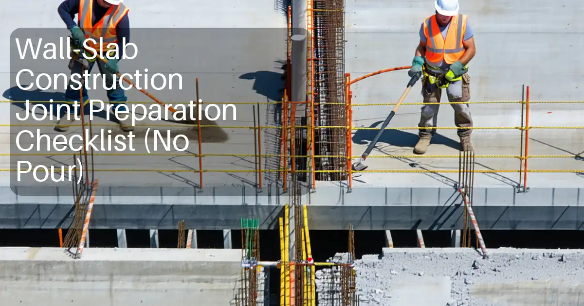
- Coordination with rebar and formwork installation, including split forms/bulkheads, kicker formation, and block-outs at penetrations.
- Pre-pour inspections and hold points; control of concrete placement and compaction around waterstops.
- Post-pour checks and documentation.
Exclusions
- Joint sealants and external membrane systems (unless directly interfacing with waterstops at terminations).
- Structural design of joints.
Key Objectives
- Achieve continuous, watertight joints with compliant splices and accurate positioning.
- Prevent displacement or damage during reinforcement installation and concrete placement.
- Record all pre-pour inspections and weld trials in the ITP.
References
| Document Type | Reference / Number | Revision | Notes |
|---|---|---|---|
| Standard | ACI 224.3R - Joints in Concrete Construction | Guidance on joint detailing and placement tolerances. | |
| Specification | ACI 301 - Specifications for Structural Concrete | Concrete placement and vibration requirements around embedded items. | |
| Standard | USACE CRD-C 572 - Waterstops, Polyvinyl Chloride (PVC) | Material and workmanship guidance for PVC waterstops and splicing evaluation. | |
| Code | BS 8102 - Protection of below ground structures against water ingress | Waterproofing selection and integration principles. | |
| Code | BS EN 1992-1-1 (Eurocode 2) | Concrete cover, placement and reinforcement interaction considerations. | |
| Standard | ASTM D412 / ASTM D638 | Tensile properties of elastomeric/plastic materials; used for comparative weld testing benchmarks [Verify per project specifications]. | |
| Standard | ISO 868 (Shore hardness) | Typical PVC waterstop hardness Shore A 70–80 [Verify per project specifications]. | |
| Manufacturer | Approved Manufacturer’s Installation Instructions (PVC and Hydrophilic Strips) | Project-approved data sheets and MSDS/SDS to govern primer/adhesive use. | |
| Project | Project Specifications and Issued for Construction (IFC) Drawings | Override default values where specified [Verify per project specifications]. |
Responsibilities
| Role | Responsibility | Name / Party |
|---|---|---|
| Project Manager | Project Manager | Main Contractor |
| Site Engineer | Site Engineer | Main Contractor |
| QA/QC Engineer | QA/QC Engineer | Main Contractor |
| HSE Officer | HSE Officer | Main Contractor |
| Installer | Waterstop Installer / Welder | Main Contractor or Specialist Subcontractor |
| Supervisor | Formwork Supervisor | Main Contractor |
| Superintendent | Concrete Superintendent | Main Contractor |
| Engineer | Engineer/Client Representative | Engineer/Client |
Resources
| Resource Type | Description | Quantity | Remarks |
|---|---|---|---|
| Personnel | Trained for PVC splicing using approved tools and jigs. | 2–4 [Verify per project scope] | |
| Personnel | Assistance with fixing, handling coils, cleaning, and protection. | 3–6 [Verify per project scope] | |
| Personnel | Witness tests and sign-off hold points. | 1 | |
| Personnel | Task-based supervision and permits. | 1 |
Materials
| Material | Specification / Grade | Quantity | Remarks |
|---|---|---|---|
| PVC waterstop, centerbulb | Factory-molded ribs; compatible with potable/non-potable exposure as specified [Verify]. | ||
| PVC waterstop, construction joint type | Meets project tensile/elongation requirements; heat-weldable. | ||
| Hydrophilic rubber/bentonite strip | Manufacturer-approved for concrete construction joints; chloride-free; resistant to hydrocarbons if required [Verify]. | ||
| Adhesive/primer | SDS available; application temperature typically >5°C [Verify]. | ||
| Clips/tie wire/nails | AISI 304/316 stainless or galvanized as specified [Verify]. |
Equipment
| Equipment | Capacity / Type | Quantity | Inspection Required |
|---|---|---|---|
| PVC waterstop welding set | |||
| Hot-air welder | |||
| Hand tools | |||
| Fixing tools | |||
| QA kit | |||
| Vibrator | 120–200 Hz | ||
| Access equipment |
Prerequisites
- Approved shop drawings and ITP; material submittals and manufacturers’ instructions endorsed for the project.
- Trained/approved PVC waterstop welders; weld procedure briefing and trial sample acceptance.
- Materials received with Certificates of Compliance; batch numbers recorded; SDS available for primers/adhesives.
- Storage: PVC coils flat, shaded, 5–35°C; hydrophilic strips sealed in original packaging; avoid water exposure before installation.
- Rebar fixed to allow clearances: minimum 50 mm concrete cover to any waterstop edge [Verify per project specifications].
- Split formwork/bulkheads prepared where required (expansion joints, stop-ends). Penetrations sleeved and detailed.
- Work area clean, dry, free of laitance and loose debris where hydrophilic strips will be bonded.
- Calibrated tools: welding iron temp check with IR thermometer; vibrators tested and tagged.
- Permits and inspections planned: pre-pour hold points scheduled with Engineer; hot work permit if required [Verify per project HSE plan and local regulations].
Method Sequence
| Step | Activity | Description | Responsibility | Inspection / Hold Point |
|---|---|---|---|---|
| 1 | Review and setting out | Review joint locations/types on IFC drawings; mark joint centerlines on forms/rebar; confirm waterstop types and transitions. | Site Engineer | ITP WP |
| 2 | Material receiving and storage | Inspect PVC coils and hydrophilic strips for damage, deformation, contamination; store per prerequisites. | QA/QC Engineer | ITP HP |
| 3 | Welder qualification and trial splice | Prepare trial butt weld using same PVC profile and iron/jig; record temp and dwell time; conduct bend/peel test. | QA/QC + Installer | ITP HP |
| 4 | Reinforcement clearance and supports | Adjust bars, chairs, and spacers to achieve minimum 50 mm cover to waterstop edges and to allow vibrator access. | Rebar/ Site Engineer | ITP WP |
| 5 | Install PVC waterstop – positioning and fastening | Uncoil and straighten PVC; centerbulb aligned to joint centerline; tie to reinforcing using stainless clips/tie wire through factory eyelets or around ribs at 200–300 mm c/c; prevent twisting and sagging. Provide additional supports near splices and corners. | Installer | ITP HP |
| 6 | PVC splicing – straight butt joints | Square-cut ends; clean and de-burr. Clamp in alignment jig. Heat both faces on iron at 200±20°C until uniform melt bead forms (approx. 20–40 s, profile dependent). Remove iron and close immediately; apply steady pressure to form 1–2 mm extrusion bead. Maintain clamping until cool (≥2–3 min). Trim flash without nicking ribs. | Installer | ITP WP |
| 7 | PVC splicing – T/L/X and transitions | Use factory-molded intersections where available; otherwise shop/field weld with dedicated jigs; make double-pass as required by profile. Reinforce quality by additional peel test for first piece of each configuration. | Installer | ITP WP |
| 8 | Formwork interface and closure checks | Fit split bulkhead around centerbulb; ensure tight contact without pinching; provide compressible foam where required by design for expansion joints. Seal around form ties to prevent grout loss along waterstop path. | Formwork Supervisor | ITP HP |
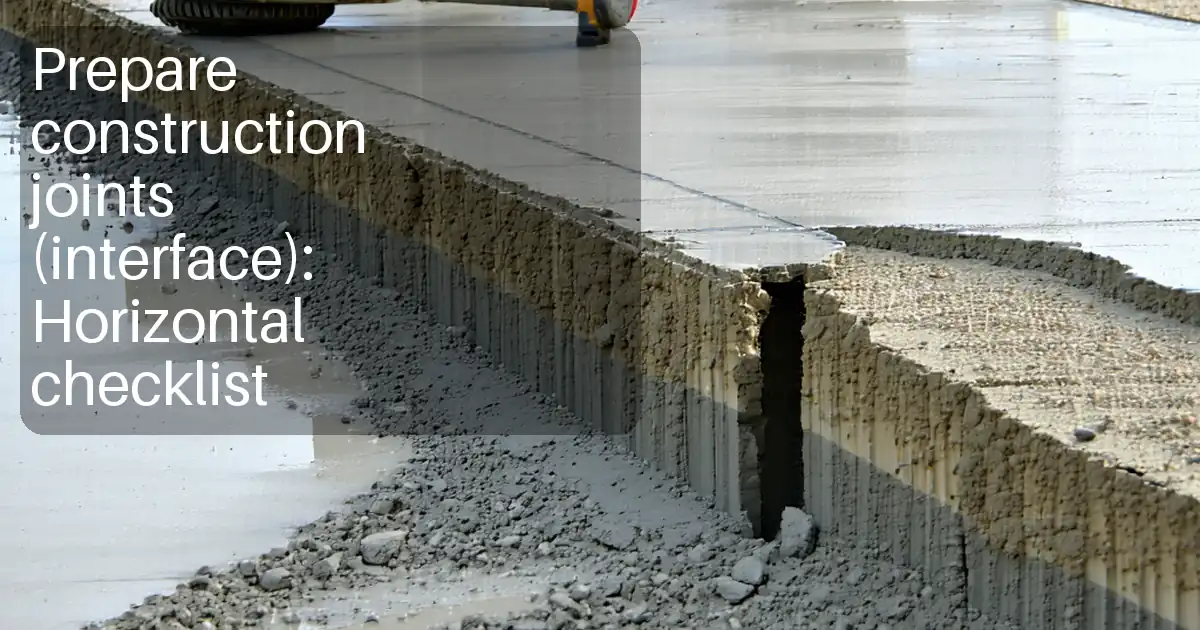
| 9 | Hydrophilic strip substrate preparation | Clean joint surface; remove laitance and dust; surface must be sound, dry, and even. Where specified, apply primer thinly and allow tack time per datasheet. | Installer | ITP WP |
| 10 | Install hydrophilic strips | Adhere strip to substrate along joint line; press firmly to achieve full contact; additional mechanical fixing with concrete nails or mesh retainer at 150–200 mm c/c. Form corners by mitre cuts; make butt joints tight (no overlap). Maintain minimum 50 mm concrete cover to any face and ≥50 mm from reinforcing steel [Verify]. Protect from water exposure prior to pour. | Installer | ITP WP |
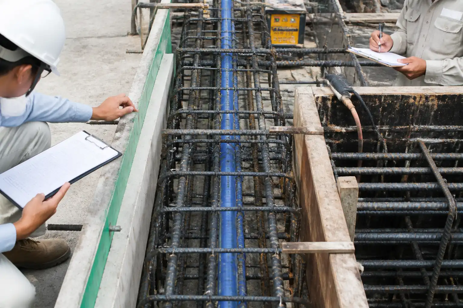
| 11 | Pre-pour final inspection | Verify continuity of PVC and hydrophilic systems; welds accepted; fixing spacing; clearances; form closure; cleanliness; protection from displacement. Obtain Engineer sign-off. | QA/QC + Engineer | ITP HP |
| 12 | Concrete placement and compaction near waterstops | Place concrete in layers 300–450 mm near waterstop; use 25–40 mm vibrators; insert vertically and withdraw slowly; maintain ≥75–100 mm slump unless specified otherwise [Verify]. Do not touch waterstop with vibrator or rebar. Monitor alignment continuously; correct promptly if displacement noted. | Concrete Superintendent | ITP WP |
| 13 | Cold joint/kicker continuation | At next lift, clean kicker; re-check exposed half of PVC ribbing; install hydrophilic strip as detailed if required for construction joint; repeat pre-pour checks. | Site Engineer | ITP WP |
| 14 | Post-pour inspection and protection | After form removal, inspect faces for honeycombing or voids along waterstop line; repair minor defects per approved method. Protect any exposed waterstop for future pours. | QA/QC + Site Engineer | ITP WP |
| 15 | Hydrostatic/watertightness testing (if applicable) | For tanks/basements as specified, perform water test after curing period. | Engineer + Contractor | ITP HP |
Health, Safety and Environment – Task-Specific Safety Controls
Principal Hazards and Controls
- Hazard: Hot surfaces from welding iron/hot-air gun
- Consequence: Burns, fire
- Engineering/Procedural Control: Use thermostatically controlled tools with stands; establish 1.5 m no-flammable zone; keep fire extinguisher CO2/dry powder within 10 m; hot work permit where required [Verify per project HSE plan and local regulations].
- PPE: Heat-resistant gloves, long sleeves, safety glasses/face shield
- Collective Measure: Fire watch during and 30 min after works in enclosed areas
-
Inspection/Permit: Hot work permit; tool PAT/inspection tags current
-
Hazard: Cutting with knives/shears
- Consequence: Lacerations
- Control: Use sharp guarded knives; cut on stable surface; cut away from body; issue cut-resistant gloves
- PPE: Cut-resistant gloves (EN 388), safety glasses
- Collective Measure: Task training and supervision
-
Inspection/Permit: Tool inspection pre-shift
-
Hazard: Rebar impalement and trip hazards around reinforcement cages
- Consequence: Puncture injuries, falls
- Control: Cap protruding rebar within work zones; maintain housekeeping; designated walkways
- PPE: Safety boots with midsole protection, hard hat
- Collective Measure: Rebar caps, exclusion zones
-
Inspection/Permit: Daily HSE walkdowns
-
Hazard: Manual handling of PVC coils and form panels
- Consequence: Strains, sprains
- Control: Team lifting for coils >20 kg; use rollers; store near point of use
- PPE: Back support as needed, gloves
- Collective Measure: Mechanical aids
-
Inspection/Permit: Manual handling training records
-
Hazard: Work at height on forms/scaffolds
- Consequence: Falls
- Control: Use compliant working platforms with toe boards; anchor fall arrest where required; ladder access angle 4:1
- PPE: Full-body harness with double lanyard where no collective protection
- Collective Measure: Guardrails, nets as applicable
-
Inspection/Permit: Scafftag/inspection before use
-
Hazard: Concrete placement/vibration
- Consequence: Pinch/crush injuries, HAVS, blowouts
- Control: Competent operators; maintain safe distance from waterstop; staged pours; monitor formwork pressures
- PPE: Gloves, eye protection, hearing protection
- Collective Measure: Exclusion around pour radius; banksman control
-
Inspection/Permit: Plant inspection, pre-pour checklist
-
Hazard: Chemical exposure to primers/adhesives (VOC)
- Consequence: Dermal/respiratory irritation
- Control: Use low-VOC products; apply in well-ventilated areas; follow SDS
- PPE: Nitrile gloves, safety glasses, half-mask respirator with organic vapor cartridges if required
- Collective Measure: Ventilation/extraction in confined spaces
-
Inspection/Permit: COSHH/SDS review; confined space permit if applicable [Verify per project HSE plan and local regulations]
-
Hazard: Confined or below-ground work (basements/tanks)
- Consequence: Asphyxiation, entrapment
- Control: Atmospheric testing; standby attendant; rescue plan
- PPE: Gas monitor as required, harness
- Collective Measure: Permit-to-work, access control
-
Inspection/Permit: Confined space permit, rescue equipment check
-
Hazard: Noise from vibrators and tools
- Consequence: Hearing loss
- Control: Select low-noise equipment, exposure time limits
- PPE: Hearing protection (SNR ≥ 25 dB)
- Collective Measure: Noise barriers where feasible
- Inspection/Permit: Noise monitoring as required
Environmental Controls
- PVC and strip offcuts: Collect in labeled containers; recycle where facility exists; otherwise dispose per project waste plan.
- Adhesives/primers: Prevent spills; use drip trays; no discharge to drains/watercourses; store in bunded areas; maintain spill kits on site.
- Odor/VOC: Choose low-VOC products where approved; schedule application during well-ventilated periods; monitor complaints.
- Dust from surface prep: Use wet methods or vacuum extraction; no dry grinding in enclosed spaces without extraction.
- Water exposure of hydrophilic strips: Protect installed strips from rain/submersion before pour to avoid premature swelling; cover with plastic sheeting or protective channels.
- Noise: Limit work hours per permit; maintain equipment; use local barriers if near receptors.
- Packaging: Segregate cardboard/plastic cores for recycling.
- Compliance: Follow project CEMP and local environmental regulations [Verify per project HSE plan and local regulations].
Quality Assurance / Quality Control
Submittals and Approvals
- Material compliance certificates for PVC waterstops and hydrophilic strips; SDS for primers/adhesives.
- Welder qualification records and trial weld procedure parameters.
- Manufacturer installation instructions and any deviations/waivers approved by Engineer.
Inspection and Testing
- Dimensional checks: Alignment to joint centerline within ±10 mm; tie spacing 200–300 mm c/c [Verify].
- Splice quality: 100% visual inspection; peel/bend test frequency 1 per 5 splices per welder per shift [Verify]. Acceptance: no cracks/voids; tensile ≥80% of parent web (benchmark per CRD-C 572/ASTM methods) [Verify].
- Hydrophilic strips: Continuity and adhesion check every 5 m; fixings at 150–200 mm c/c; butt joints tight ≤2 mm; minimum 50 mm cover maintained [Verify].
- Concrete placement records: Slump, vibrator type/head size, lift thickness near waterstop, observations of displacement.
Records
- ITP checklists with hold/witness points, weld logs, HP releases, photo records before pour, NCR and corrective actions, as-built markups.
Nonconformities and Repairs
- PVC splice with defects: Cut out and re-weld using longer insert piece; re-test per frequency.
- Misalignment > tolerance: Re-fix and secure prior to pour; if poured, assess and inject/repair per approved method.
- Hydrophilic gaps/damage: Remove affected length plus 100 mm either side; re-install and re-inspect.
Calibration and Control
- Verify welding iron temperature with IR thermometer at start and mid-shift; record values ±10°C of set point [Verify].
- Tooling and measurement equipment within valid calibration periods.
Attachments
- Manufacturer data sheets and installation guides for PVC waterstops and hydrophilic strips.
- SDS for primers/adhesives.
- Weld trial log template and weld register.
- Pre-pour inspection checklist (waterstops and hydrophilic strips).
- Typical details: expansion joint centerbulb, construction joint ribbed waterstop, intersections (T/L/X), penetration details, kicker joint, and hydrophilic strip placement.
- ITP forms with hold/witness points and sign-off blocks.
This content is a read-only public reference. Download or customize to get an editable version.
ITP preview
The first inspection activities from the linked ITP for Method Statement: Installation of PVC and Hydrophilic Swellable Waterstops in Concrete Construction and Expansion Joints:
| Activity | Inspection / Test | Acceptance Criteria | Responsibility | Record |
|---|---|---|---|---|
| Material delivery inspection (PVC and hydrophilic) | Visual check, documents review (CoC, SDS) | Materials undamaged; certificates match specs; batch numbers recorded. | QA/QC + Engineer | MIR/MRR, photos, material log |
| Welder qualification and trial splice | Bend/peel test on sample weld | No cracking/delamination; strength ≥80% of parent web [Verify]. | QA/QC + Engineer | Weld trial report, sample label |
| Setting out of joint and waterstop type confirmation | Check vs IFC drawings | Correct joint location/type; transitions confirmed. | Site Engineer | Setting-out check sheet |
Showing 3 of 13 inspection activities. View full ITP →
Related Inspection and Test Plan
An Inspection and Test Plan (ITP) is available for Method Statement: Installation of PVC and Hydrophilic Swellable Waterstops in Concrete Construction and Expansion Joints. The ITP defines the inspection activities, acceptance criteria, hold and witness points, responsible parties, and records required to verify the work described in this method statement.
View the Method Statement: Installation of PVC and Hydrophilic Swellable Waterstops in Concrete Construction and Expansion Joints ITP →Frequently asked questions
Continue with related Quollnet resources connected to this method statement.