Method Statement: Placement and Compaction of Concrete in Deep Vertical Elements (Columns and Shear Walls) – Method Statement
AI-assisted method statement with matching ITP, PDF download, and Excel export.
More than a static template
Unlike a downloadable Word or PDF template, this method statement is an AI-assisted editable starting point connected directly to a matching Inspection and Test Plan. Every section is structured, project-adaptable, and ready to export.
- AI-assisted drafting — Customize every section with AI for your specific project scope.
- Linked ITP — A matching inspection and test plan is generated alongside the method statement.
- Multiple export formats — Download as a formatted PDF or editable Excel spreadsheet.
- Editable starting point, not a final document — Review, verify, and adjust all content against your project requirements before use.
Static template vs. Quollnet workflow
| Feature | Static template | Quollnet |
|---|---|---|
| Project-specific content | Manual fill-in required | AI-assisted customization |
| Linked ITP | Separate document, no link | Matching ITP included |
| Export formats | Usually PDF only | PDF and Excel |
| Structured sections | Free-form layout | 13 standardized sections |
| Saved to your account | Local file only | Cloud-saved, reusable |
| Content accuracy | You verify everything | AI-assisted, you still verify |
| Cost | Often free but time-intensive | Free to customize and download |
What you can customize
When you save this method statement to your account, every section becomes editable. The following 13 sections are included:
- Scope — Defines the activity and its boundaries.
- References — Standards, specifications, and drawings.
- Responsibilities — Roles and accountabilities.
- Resources — Labour, plant, and equipment summary.
- Materials — Materials and compliance requirements.
- Equipment — Tools and equipment details.
- Prerequisites — Hold points and pre-conditions.
- Method sequence — Step-by-step construction sequence.
- Safety controls — HSE risk controls and PPE.
- Environmental controls — Environmental mitigation measures.
- QA/QC — Quality inspection and test requirements.
- ITP — Inspection and Test Plan table (has its own page).
- Attachments — Referenced drawings and documentation.
Why this method statement is used
This method statement is used to define and communicate the approved procedure for carrying out method statement: placement and compaction of concrete in deep vertical elements (columns and shear walls) on site. It ensures the work is planned in advance, the correct resources and controls are in place, and all personnel understand responsibilities, sequence, quality requirements, and safety controls before work begins. It aligns site execution with the documented scope and acceptance expectations.
Who uses this method statement
This method statement is used by contractors, site supervisors, project engineers, QA/QC engineers, HSE officers, consultants, and client representatives. It serves as a shared reference for planning, execution, supervision, inspection, and approval of the activity on site.
When it is prepared and submitted
The method statement is prepared before the work activity starts and submitted as part of the pre-construction documentation package for review and approval.
Who reviews or approves it
The method statement is usually submitted to the client representative, consultant, resident engineer, or project management consultant for review and approval before the work commences.
Important approval note
This method statement is an AI-assisted editable starting point, not a pre-approved document. Before use on any project, all content must be reviewed and approved by the relevant parties (superintendent, principal contractor, or client representative) in accordance with your contract and project quality plan.
For example: if your specification requires a departure from a referenced standard, that departure must be documented and approved separately — this method statement will not capture that automatically. Always verify against your applicable drawings, specifications, and regulatory requirements.
Method statement content
Scope
Work Included
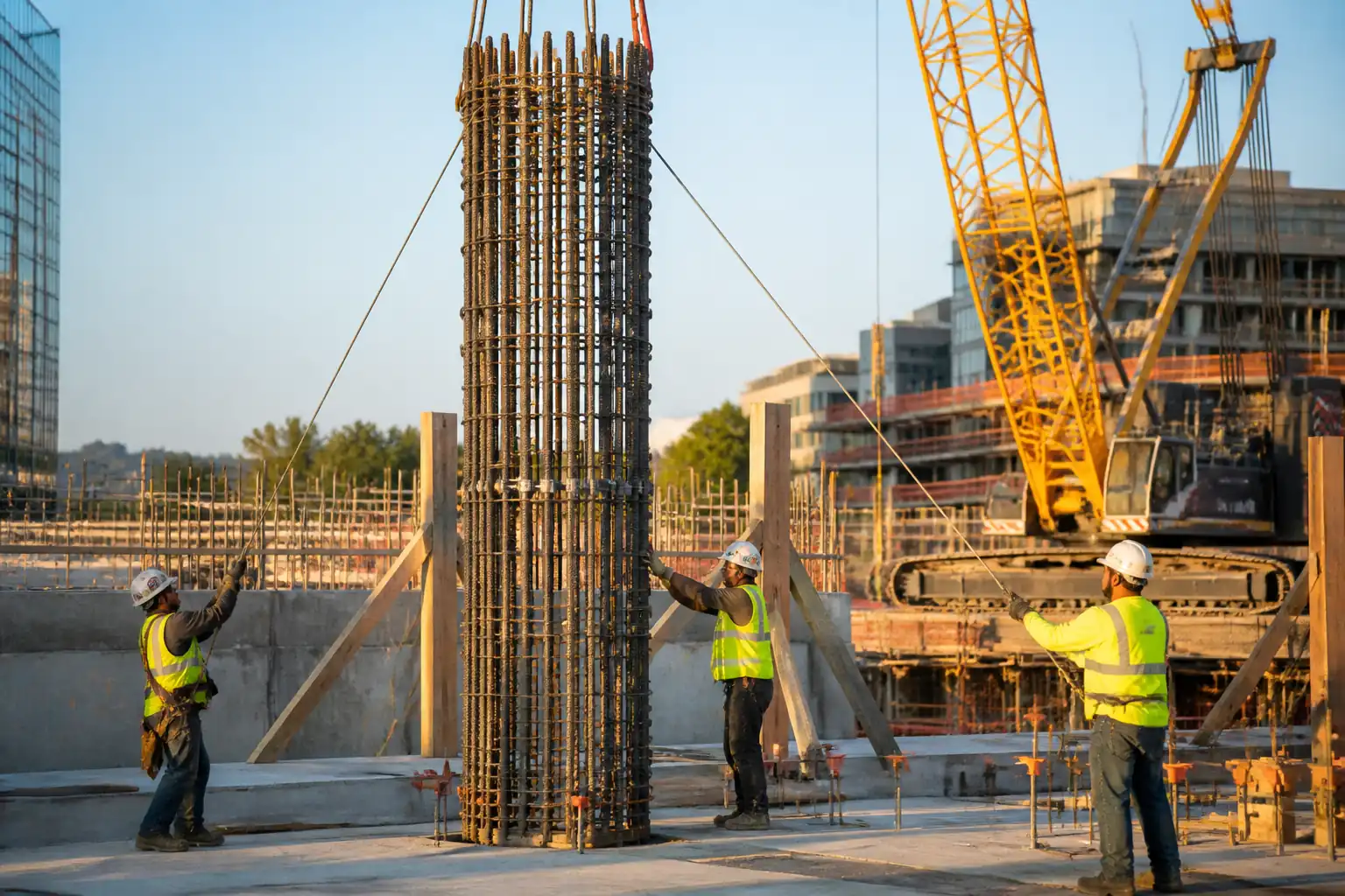
- Placement and compaction of normal-weight concrete in cast-in-place vertical elements (columns and shear walls), including high lifts and congested reinforcement zones.
- Control of maximum free-fall, use of elephant trunk/drop chute or pumped hose to minimize segregation, pacing of lift height and rate-of-rise, and internal/external vibration to achieve consolidation without honeycombing.
- Pre-pour checks of formwork, reinforcement, and embedded items; delivery verification and fresh concrete testing; curing; surface inspection; rectification of minor defects; documentation.
Exclusions
- Underwater or tremie concrete below waterline (separate method required); precast elements; mass concrete thermal control plans (separate if required).
Objectives
- Achieve specified strength and durability, dimensional tolerances, alignment/plumb, cover, and surface quality.
- Maintain safe operations with controlled formwork pressure and preventing segregation and cold joints.
Interfaces
- Coordination with reinforcement, MEP sleeves/inserts, formwork/falsework, survey, and QA/QC testing agency.
References
| Document Type | Reference / Number | Revision | Notes |
|---|---|---|---|
| Standard | ACI 301; ACI 318 [Verify edition per project] | Materials, placement, curing, acceptance criteria. | |
| Standard | ACI 304R; ACI 309R | Free-fall control, placement methods, vibrator selection and use. | |
| Standard | ACI 347R | Used to determine permissible placement rate and monitoring. | |
| Standard | ASTM C31, C39, C94, C138, C143, C173/C231, C1064 | Testing and acceptance of fresh and hardened concrete. | |
| Standard | ASTM C94; BS EN 206 | Production, delivery, conformity requirements. | |
| Standard | BS EN 13670; ACI 117 | Execution controls and dimensional tolerances. | |
| Standard | ACI 305R; ACI 306R | Environmental control during placement and curing. | |
| Standard | ISO 9001; ISO 14001; ISO 45001 | Project management frameworks [Verify per project]. |
Responsibilities
| Role | Responsibility | Name / Party |
|---|---|---|
| Construction Manager | Construction Manager | Contractor |
| Site Engineer | Site Engineer / General Foreman | Contractor |
| QA/QC Engineer | QA/QC Engineer | Contractor |
| Supplier Rep | Ready-Mix Supplier Representative | Supplier |
| Lab Technician | Independent Testing Agency | Independent |
| HSE Officer | HSE Manager / Officer | Contractor |
| Surveyor | Surveyor | Contractor |
Resources
| Resource Type | Description | Quantity | Remarks |
|---|---|---|---|
| Skilled labor | Pump hoseman, vibrator operators, placers, finishers | 1 crew per pour (6–10 persons) [Verify per pour size] | |
| Technicians | Sampling, testing, documentation | 2–3 persons | |
| HSE officers | Monitoring and controls | 1 per active pour face |
Materials
| Material | Specification / Grade | Quantity | Remarks |
|---|---|---|---|
| Concrete to ASTM C94 / BS EN 206 | Strength class per drawings (e.g., C30/37 or 35 MPa @ 28d) [Verify] | Slump 120–180 mm for pumped concrete [Verify]. Max w/cm per durability class [Verify]. | |
| ASTM C494 admixtures | Type F/G HRWR; Type D retarder [Verify] | Compatibility confirmed by approved mix design | |
| ASTM C309 / C1315 | Membrane-forming curing compound | White pigmented where solar exposure; potable-water compatible in water-retaining structures [Verify] | |
| Epoxy or polymer-modified bonding agent | Manufacturer’s data [Verify] | Use only if specified; otherwise SSD + laitance removal |
Equipment
| Equipment | Capacity / Type | Quantity | Inspection Required |
|---|---|---|---|
| Truck-mounted boom pump | 60–100 m³/h [Verify] | 1 (plus standby if critical) | Pre-pour inspection |
| 125–150 mm hose with reducers to 75–100 mm | Min. 1 per pour face, plus 1 spare | Visual check; secure lanyards | |
| Electric/pneumatic, 25–50 mm heads | 12,000–18,000 vpm | 2 operating + 1 standby per pour face | Function test; PAT/inspection certs |
| Clamp-on form vibrators | As required by formwork design | Mounting bolts torque check | |
| ASTM-compliant apparatus | 1 set per sampling point | Calibration certs valid | |
| Formwork per design; platforms; ladders | Per drawings | Pre-pour formwork checklist | |
| LED lights; two-way radios | As required | Function check |
Prerequisites
Approvals and Documentation
- Approved mix designs, method statement, ITP, shop drawings, and formwork design calculations [Verify per project].
- Permits-to-Work (PTW) for concrete pumping, working at height, lifting (if bucket used), and hot/cold weather procedures [Verify per project HSE plan and local regulations].
- Calibration and inspection certificates for pumps, vibrators, testing equipment, lifting accessories, and electrical tools.
Site Readiness
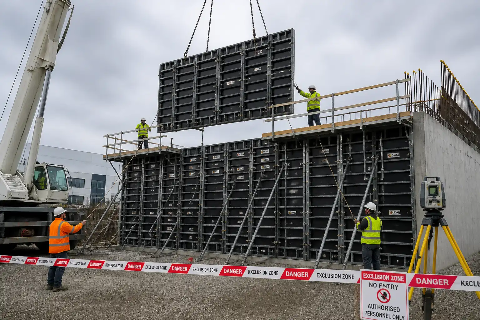
- Formwork installed, braced, and inspected for tightness, plumb, alignment, and pressure rating. Chamfers, blockouts, construction joint formers, and waterstops (if any) fixed.
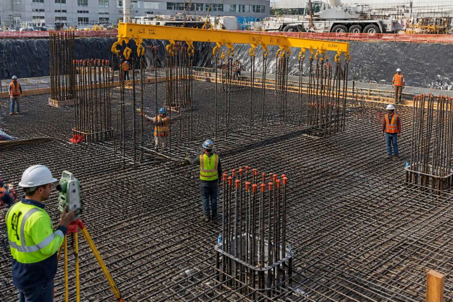
- Reinforcement inspected: size, spacing, cover blocks/chairs, cleanliness, tying, congestion relief measures, clear pour paths, and embedded items (anchors, couplers, conduits) fixed and recorded.
- Access/egress, platforms, edge protection, lighting, exclusion zones, and clear line-of-sight/communications established.
- Pour plan issued: sequence, lift heights, target rate-of-rise, equipment layout, crew assignments, emergency stop signals, contingency (standby vibrator/pump).
Pre-Pour Trials/Controls
- Mock-up (as required) to validate surface finish/bughole expectations and compaction approach.
- Trial to confirm vibrator head size, insertion grid, and ability to penetrate congested zones without damaging reinforcement.
- Environmental plan in place for pump priming/washout capture and noise controls.
Method Sequence
| Step | Activity | Description | Responsibility | Inspection / Hold Point |
|---|---|---|---|---|
| 1 | Pre-pour coordination meeting | Brief crew on sequence, rate-of-rise, free-fall limits, vibrator plan, testing points, safety roles, and communications. | Construction Manager / Site Engineer | Attendance and briefing records |
| 2 | Formwork and reinforcement final inspection | Check form tightness, ties, shutters, kicker levels, blockouts, embedded items; verify cover with spacers; ensure clean, free of debris and standing water. | QA/QC Engineer, Site Engineer, Consultant | Joint inspection (IR) |
| 3 | Equipment readiness | Position pump, set outriggers on mats; rig elephant trunk/hose to reach near placement point; test vibrators incl. standby; confirm radio channels. | Site Engineer / Pump Operator / HSE | Pre-use inspections |
| 4 | Delivery verification and fresh concrete tests | Check delivery tickets (time, mix ID, w/cm, admixtures); conduct slump, temperature, and air (if specified); cast trial specimens per ITP. | QA/QC Technician | Sampling per ASTM C172 |
| 5 | Placement start and initial lift | Prime pump; start at lowest point/pour corner; maintain hose/elephant trunk outlet within 300–600 mm of the rising concrete surface to limit free-fall. | Hoseman / Foreman | Continuous supervision |
| 6 | Consolidation by internal vibration | Insert vibrator vertically; spacing at ~1.5× radius of influence (typ. 250–375 mm); penetrate 75–100 mm into previous lift; duration 5–15 s until bubbles cease and surface sheens; withdraw at 80–150 mm/s; avoid touching rebar/form. | Vibrator Operators (trained) | Foreman and QA/QC check |
| 7 | Rate-of-rise control | Control placement to keep rate-of-rise within formwork design. Typical target 1.0–1.5 m/h unless otherwise justified by mix temp and form pressure design [Verify]. Use lift heights of 0.6–1.2 m per pass and cycle around pour face to balance pressure. | Site Engineer / Foreman | Monitor time and height marks on form |
| 8 | Congested zones and embeds | Use reduced hose diameter and smaller vibrator head (25–32 mm) to thread between reinforcement; pre-place via trunk directly; apply short, frequent insertions. | Hoseman / Vibrator Operator | Supervisor watchpoints |
| 9 | Cold joint prevention/management | Maintain continuous supply. If interruption > initial set is likely, stop at approved construction joint; roughen/laitance removal at restart; SSD condition; bonding agent if specified. | Site Engineer / QA/QC | Approval of joint location |
| 10 | Top surface strike-off (if exposed) | Screed/float to level or specified finish at top of column/wall; form-face remains undisturbed. | Finishers | Visual |
| 11 | Curing | Maintain moisture immediately after final set or upon striking forms. Options: continuous moist curing ≥7 days, or curing compound meeting ASTM C309/C1315 [Verify]; protect from thermal shock, wind, and sun. | Site Engineer / Foreman | Daily curing inspection |
| 12 | Form striking and inspection | Strike forms when concrete has sufficient strength to support itself and imposed loads [Verify per spec]. Inspect surfaces for honeycombing/voids; carry out minor patching per approved repair method. | Site Engineer / QA/QC / Consultant | Hold point (form removal) |
| 13 | Testing and acceptance | Compressive strength testing per ITP; dimensional survey; cover checks by cover meter (if specified). | QA/QC, Independent Lab, Surveyor | Sampling and laboratory tests |
Health, Safety and Environment – Task-Specific Safety Controls
Principal Hazards and Controls
- Hazard: Formwork overpressure and failure
- Consequence: Collapse, struck-by, concrete spill, severe injury/fatality
- Engineering/Procedural Control: Verify form design and pressure rating; control rate-of-rise (1.0–1.5 m/h typical [Verify]); continuous inspection for bulging/leaks; balance pour sequence; stop-work if movement observed; use through-ties per design.
- PPE: Safety helmet, eye protection, gloves, safety boots
- Collective Measure: Exclusion zones under/around formwork; working platforms with guardrails
-
Inspection/Permit: Pre-pour formwork inspection checklist and sign-off; hold point release by Supervisor/Engineer
-
Hazard: Pump line/hose burst or whipping
- Consequence: Impact injuries, concrete spray, eye injuries
- Control: Rated hoses with valid inspection tags; whip-checks and end-hose safety lanyards; secure clamps; prime at low pressure; no kinks; clear communication before restarts; relieve pressure before disconnection.
- PPE: Face shield/safety goggles, gloves, boots
- Collective Measure: Exclusion zone at hose end; barricades and spotter
-
Inspection/Permit: Pump inspection record; daily pre-use; operator certification [Verify per project HSE plan and local regulations]
-
Hazard: Falls from height (working platforms/scaffolds)
- Consequence: Serious injury/fatality
- Control: Certified platforms with guardrails and toe boards; tie-in per design; use fall arrest where required; maintain 3-point contact on ladders.
- PPE: Full-body harness with double lanyard (if no guardrail), helmet
- Collective Measure: Fixed access, edge protection, ladder cages
-
Inspection/Permit: Scafftag/inspection records; PTW for work at height
-
Hazard: Contact with wet concrete (alkaline burns)
- Consequence: Chemical burns, dermatitis, eye damage
- Control: Avoid skin contact; barrier cream; immediate washing facilities; safe handling of washout; no compressed air cleaning.
- PPE: Alkali-resistant gloves, long sleeves, waterproof boots, eye protection
- Collective Measure: Eyewash stations; clean water supply
-
Inspection/Permit: HSE toolbox; SDS available on site
-
Hazard: Struck-by from moving plant/boom
- Consequence: Crush injuries
- Control: Designated pump setup with spotter; segregated pedestrian routes; slew/boom limits as required; radio communication protocols.
- PPE: Hi-vis vest, helmet, boots
- Collective Measure: Barriers, banksman control
-
Inspection/Permit: Plant inspection; operator license verification
-
Hazard: Electrical hazards (corded vibrators/lighting)
- Consequence: Electric shock, burns
- Control: 110V center-tapped or RCD-protected circuits; intact cables; dry handling; PAT tested equipment.
- PPE: Insulated gloves where required, dry-grip gloves
- Collective Measure: Distribution boards with RCD; cable management
-
Inspection/Permit: PAT tags valid; pre-use checks
-
Hazard: Rebar impalement and trip hazards
- Consequence: Lacerations, impalement
- Control: Cap protruding bars; housekeeping for hoses/lines; maintain clear walkways.
- PPE: Helmet, gloves, boots
- Collective Measure: Rebar caps, barriers
-
Inspection/Permit: Daily HSE inspection
-
Hazard: Noise and hand–arm vibration (HAV)
- Consequence: Hearing loss, HAVS
- Control: Select low-vibration tools; rotate operators; limit exposure duration; maintain vibrators.
- PPE: Hearing protection
- Collective Measure: Noise mapping and signage
-
Inspection/Permit: HAV monitoring records
-
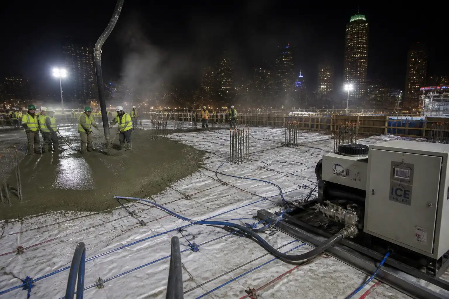
Hazard: Hot/cold weather concreting
- Consequence: Thermal cracking, reduced strength; heat stress/hypothermia
- Control: Apply ACI 305R/306R measures; chilled water/ice or heated materials as applicable; sunshades/windbreaks; hydration and rest breaks.
- PPE: Weather-appropriate PPE
- Collective Measure: Shade tents/heat recovery areas; warm shelters in cold
- Inspection/Permit: Weather plan approval
[All controls to be verified per project HSE plan and local regulations].
Environmental Controls
Environmental Risks and Mitigations
- Concrete washout and pump prime discharge
- Impact: Alkaline contamination of soil/water
-
Control: Lined washout pits or portable containers; collect and dispose via approved waste stream; prohibit ground discharge.
-
Concrete spills and leakage from forms
- Impact: Ground contamination, resource waste
-
Control: Seal form joints; spill kits staged; immediate recovery and disposal; protect drains with socks/booms.
-
Noise from pumps and vibrators (especially night works)
- Impact: Nuisance to receptors
-
Control: Schedule daytime where possible; acoustic shrouds/barriers; maintain equipment; comply with permit limits [Verify].
-
Dust/traffic pollution from trucks
- Impact: Air quality, track-out
-
Control: Wheel-wash, road sweeping, speed limits, designated routes.
-
Waste minimization
- Impact: Resource efficiency
-
Control: Order concrete per pour plan; real-time truck call-off to reduce returns; segregate waste; return surplus via supplier recovery where available.
-
Water use/runoff
- Impact: Silted or alkaline runoff
- Control: Prevent uncontrolled water jetting; use closed-loop cleaning where feasible; treat/settle before discharge per permit.
[Verify requirements per environmental management plan and local regulations].
Quality Assurance and Quality Control
Fresh Concrete Acceptance (per ASTM C94/BS EN 206)
- Slump: 120–180 mm for pumped placement [Verify per mix]. Tolerance ±25 mm unless otherwise specified.
- Temperature: 10–32°C at discharge [Verify climate/spec].
- Air content: As specified (typically 4–6% for air-entrained; 1–3% for non-air) [Verify].
- Delivery time: Discharge within 90 minutes or 300 drum revolutions unless retarder/temperature justify extension per ASTM C94 [Verify]. Water addition only by authorized person; document adjustments.
Placement and Compaction Controls
- Maximum free-fall without trunk/hose: ≤1.5 m. For deeper drops, use elephant trunk/pump hose so outlet is within 300–600 mm of surface being placed.
- Vibrators: Head 25–50 mm; vpm 12,000–18,000; insertion spacing ~1.5× radius of influence (typ. 250–375 mm); immersion 75–100 mm into previous lift; time 5–15 s until bubbles cease; slow withdrawal; do not contact rebar/forms.
- Rate-of-rise: As per form design; typical 1.0–1.5 m/h [Verify per ACI 347R and supplier]. Mark heights/time; inspect for leaks or bulging.
Tolerances (typical) [Verify per project]
- Plumb: ±6 mm per 3 m height, not to exceed ±12 mm total per element.
- Dimensions: ±10 mm (columns/walls typical).
- Cover: As per drawings; tolerance −6/+10 mm (ACI 117 typical).
- Surface quality: No honeycombing; bugholes within class finish limits; edges and arrises sound.
Testing Frequency (typical) [Verify per ITP]
- Slump/temperature: Each truck.
- Air content: First truck, each change, then at least every 25–50 m³.
- Density/unit weight (if required): Each sample set.
- Compressive strength: 1 set (≥6 cylinders) per 50 m³ or per pour/day minimum; test at 7 and 28 days (2 each) with spares.
Records and Closeout
- Maintain pour log (start/stop, rise rate), compaction log (insertion grid), test reports, IRs, NCRs and CARs if applicable, curing log, as-built survey. Release element only after achieving required criteria.
Attachments
- Pour plan and time–height calculator (rate-of-rise worksheet)
- Pre-pour formwork/rebar checklist
- Pump and vibrator pre-use inspection forms
- Concrete test plan and sampling locations
- Curing plan (hot/cold weather addendum as applicable)
- Emergency response plan (line burst, formwork distress)
- Material approvals: mix designs, admixture data sheets, curing compound TDS/SDS
- Equipment calibration and inspection certificates
- Example compaction log sheet and pour card
This content is a read-only public reference. Download or customize to get an editable version.
ITP preview
The first inspection activities from the linked ITP for Method Statement: Placement and Compaction of Concrete in Deep Vertical Elements (Columns and Shear Walls):
| Activity | Inspection / Test | Acceptance Criteria | Responsibility | Record |
|---|---|---|---|---|
| Pre-pour documentation review | Approval of MS, ITP, mix designs, formwork design | All approvals in place; latest revisions used | QA/QC Engineer / Consultant | Approval sheets, transmittals |
| Formwork and reinforcement inspection | Dimensional/plumb checks; cover verification; cleanliness | Within tolerance per ACI 117/BS EN 13670; forms tight; embeds fixed | QA/QC Engineer / Consultant | IR, checklist, photos |
| Equipment readiness | Pump/vibrator function; safety devices; permits | Operational and certified; PTWs active | Site Engineer / HSE | Pre-use forms, PTW |
Showing 3 of 10 inspection activities. View full ITP →
Related Inspection and Test Plan
An Inspection and Test Plan (ITP) is available for Method Statement: Placement and Compaction of Concrete in Deep Vertical Elements (Columns and Shear Walls). The ITP defines the inspection activities, acceptance criteria, hold and witness points, responsible parties, and records required to verify the work described in this method statement.
View the Method Statement: Placement and Compaction of Concrete in Deep Vertical Elements (Columns and Shear Walls) ITP →Frequently asked questions
Continue with related Quollnet resources connected to this method statement.