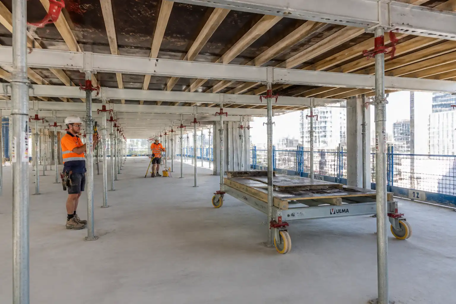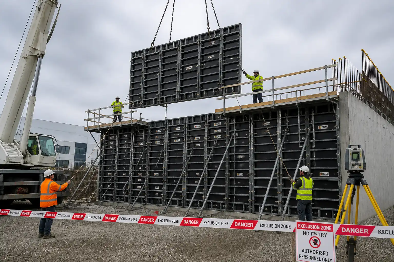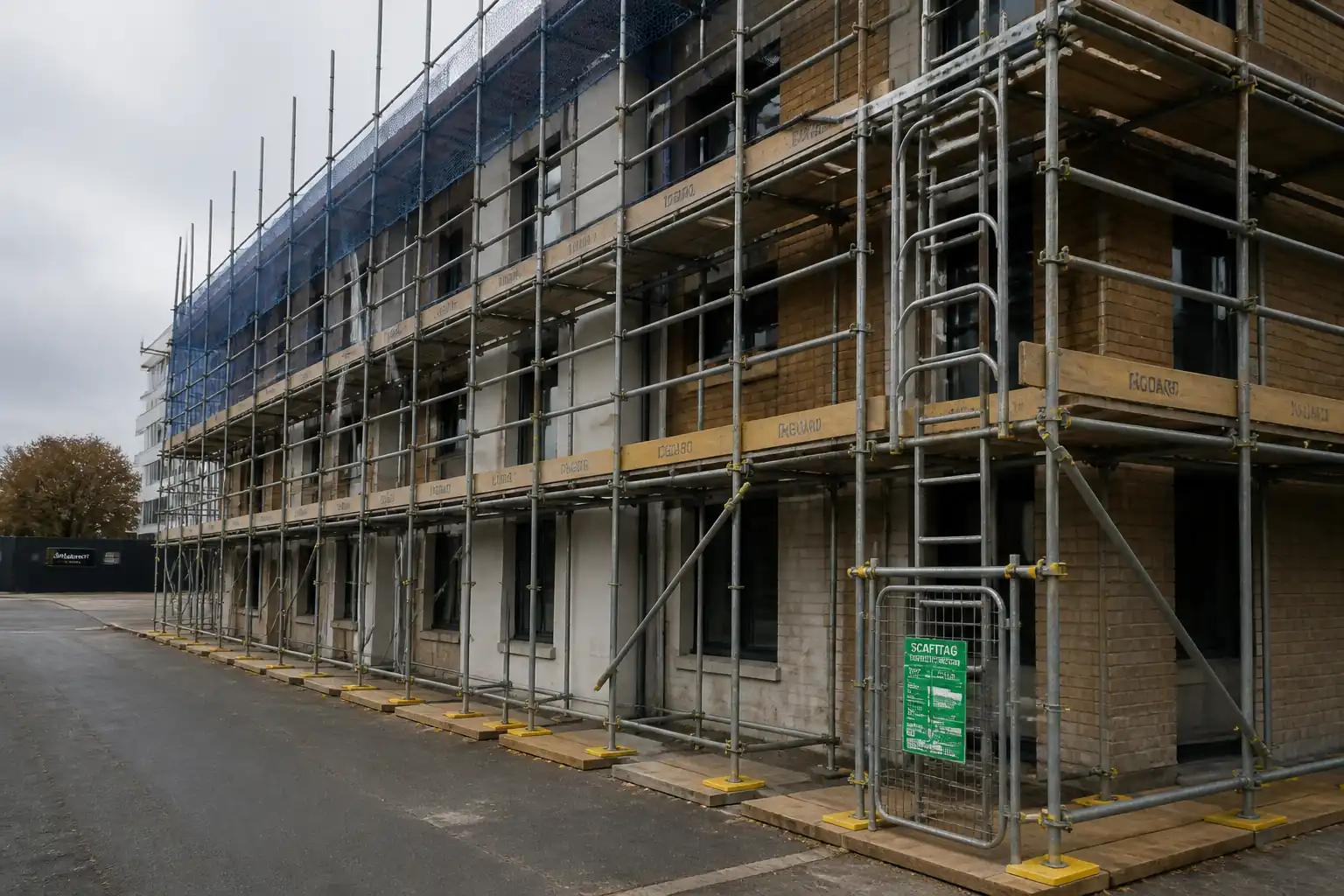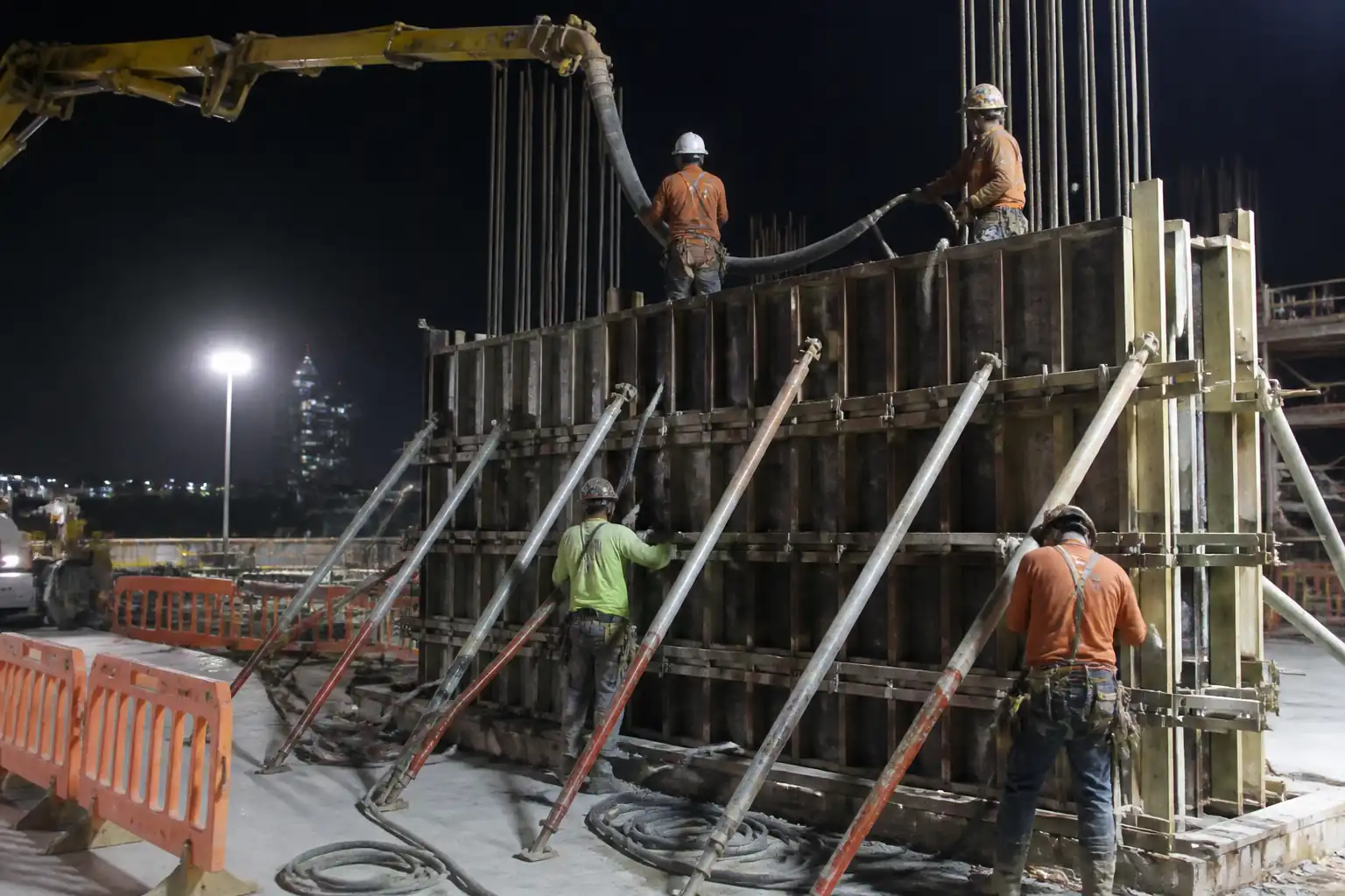
Inspection and Test Plan for Method Statement: Temporary Formwork and Falsework Support System for Reinforced Concrete Structural Elements
AI-assisted inspection and test plan connected to a method statement, with PDF and Excel export.
More than a static template
Unlike a downloadable Word or PDF template, this ITP is an AI-assisted editable starting point directly connected to its method statement. Every inspection activity, hold point, and acceptance criterion is structured and ready to adapt to your project.
- AI-assisted customization — Tailor inspection activities and acceptance criteria to your specific project scope.
- Linked method statement — This ITP is connected to the corresponding method statement describing the work sequence.
- Multiple export formats — Download as a formatted PDF or editable Excel spreadsheet.
- Editable starting point, not a final document — Review and verify all content against your project specifications and standards before use.
What you can customize
When you save this ITP to your account, every inspection row becomes editable. You can add, remove, or modify:
- Inspection activity — Description of what is being inspected.
- Inspection type — Hold point (H), Witness point (W), Review (R), or Monitor (M).
- Responsibility — Contractor, subcontractor, engineer, or client.
- Frequency — How often the inspection occurs.
- Acceptance criteria — Referenced standard or specification requirement.
- Records — Forms, test reports, or checklists required as evidence.
Why this ITP is used
To verify that temporary works are safely designed, correctly erected, and fit for loading and striking without endangering workers or permanent works.
Who uses this inspection and test plan
Temporary works designers, TWC/TWS, QA/QC inspectors, site engineers, and concrete supervisors.
When this ITP is prepared and submitted
From design submission through erection, pre‑pour hold point, during concrete placement, and through striking/back‑propping removal.
Who receives or approves this ITP
Main Contractor and Engineer/Consultant for review/approval [Verify per contract].
Inspection scope
Design approval, material verification, geometry checks, bracing and connections, pre‑pour HP1, pour monitoring WP1, strike HP2, and back‑propping controls.
Typical hold, witness, and review points
HP1: Pre‑pour authorization; WP1: Pour monitoring; HP2: Striking authorization.
Typical inspection records
Approved design, inspection checklists, survey reports, concrete test results, permits (Load/Strike), photos, NCRs, as-built sketches.
Important approval note
This ITP is an AI-assisted editable starting point, not a pre-approved document. Before use on any project, all inspection activities, hold points, and acceptance criteria must be reviewed and approved by the relevant parties (superintendent, principal contractor, or client representative) in accordance with your contract and project quality plan.
Always verify acceptance criteria against your applicable drawings, specifications, and regulatory requirements. Hold points must be confirmed with the relevant authority before work proceeds past that point.
Inspection and test plan
| Activity | Inspection / Test | Acceptance Criteria | Responsibility | Record |
|---|---|---|---|---|
| Design submission and independent check | Review of drawings/calcs vs BS 5975/EN 12812/ACI 347 | Design approved; category check completed [Verify] | TWD/TWC | Approved design; check certificate |
| Material verification on delivery | Certificates, visual condition | Correct grades/classes; undamaged; traceable | QA/QC | Delivery inspection report; CoC |
| Ground/soffit bearing capacity check | Plate load test or calculation review | Allowable bearing ≥ design reaction with FS ≥ 2.0 [Verify] | Site Engineer/TWS | Bearing calc/test record |
| Erection of primary supports and bracing | Visual/plumb/level/engagement checks | Plumb ≤ 1/500; level ±5 mm; connections secured; bracing per design | TWS/QA | Erection checklist |
| Decking/panels alignment and fixings | Spacing/fastener checks; survey | Beam spacing ±10 mm; panel joints supported; fixings per manufacturer | TWS/QA | Survey report; checklist |
| Embeds/openings positioning | Tape/total-station check | Position within ±10 mm plan/level [Verify] | QA/QC/Site Engineer | Inspection record; photos |
| Pre-pour hold point (HP1) | Full checklist including access/edge protection | Permit-to-Load issued; all items satisfactory | TWC/TWS/QA | HP1 form; Permit-to-Load |
| Concrete placement monitoring (WP1) | Rate-of-rise vs allowable; slump/temperature | Within TWD limits; no distress/overstressing | Concrete Supervisor/TWS | Pour log; test results |
| Post-pour inspection | Settlement/deflection check; connections review | No unexpected movement; system secure | TWS/QA | Post-pour checklist |
| Striking hold point (HP2) | Strength verification (cubes/cylinders/maturity) vs criteria; review weather and curing | Meets TWD strike strength and sequence requirements | TWC/TWD/QA | HP2 form; Permit-to-Strike; test reports |
| Back-propping installation check | Position, capacity, engagement | Per design drawings; tagged and secure | TWS/QA | Checklist; photos |
| Final removal of back-props | Strength confirmation; structural continuity achieved | Meets TWD criteria; no adverse deflection/cracking | TWC/QA | Permit-to-Remove Back-props |
This table is a read-only public reference. Download the PDF or Excel version, or customize this ITP to edit it for your project.
Frequently asked questions
Related method statement
This Inspection and Test Plan is associated with the Method Statement: Temporary Formwork and Falsework Support System for Reinforced Concrete Structural Elements method statement, which describes the step-by-step construction sequence, resources, materials, equipment, safety controls, and environmental controls for this activity.
View the Method Statement: Temporary Formwork and Falsework Support System for Reinforced Concrete Structural Elements method statement →Continue with related inspection, method statement, article, and checklist resources.