
Method Statement: Independent Scaffold Erection for Façade Construction Works – Method Statement
AI-assisted method statement with matching ITP, PDF download, and Excel export.
More than a static template
Unlike a downloadable Word or PDF template, this method statement is an AI-assisted editable starting point connected directly to a matching Inspection and Test Plan. Every section is structured, project-adaptable, and ready to export.
- AI-assisted drafting — Customize every section with AI for your specific project scope.
- Linked ITP — A matching inspection and test plan is generated alongside the method statement.
- Multiple export formats — Download as a formatted PDF or editable Excel spreadsheet.
- Editable starting point, not a final document — Review, verify, and adjust all content against your project requirements before use.
Static template vs. Quollnet workflow
| Feature | Static template | Quollnet |
|---|---|---|
| Project-specific content | Manual fill-in required | AI-assisted customization |
| Linked ITP | Separate document, no link | Matching ITP included |
| Export formats | Usually PDF only | PDF and Excel |
| Structured sections | Free-form layout | 13 standardized sections |
| Saved to your account | Local file only | Cloud-saved, reusable |
| Content accuracy | You verify everything | AI-assisted, you still verify |
| Cost | Often free but time-intensive | Free to customize and download |
What you can customize
When you save this method statement to your account, every section becomes editable. The following 13 sections are included:
- Scope — Defines the activity and its boundaries.
- References — Standards, specifications, and drawings.
- Responsibilities — Roles and accountabilities.
- Resources — Labour, plant, and equipment summary.
- Materials — Materials and compliance requirements.
- Equipment — Tools and equipment details.
- Prerequisites — Hold points and pre-conditions.
- Method sequence — Step-by-step construction sequence.
- Safety controls — HSE risk controls and PPE.
- Environmental controls — Environmental mitigation measures.
- QA/QC — Quality inspection and test requirements.
- ITP — Inspection and Test Plan table (has its own page).
- Attachments — Referenced drawings and documentation.
Why this method statement is used
This method statement is used to define and communicate the approved procedure for carrying out method statement: independent scaffold erection for façade construction works on site. It ensures the work is planned in advance, the correct resources and controls are in place, and all personnel understand responsibilities, sequence, quality requirements, and safety controls before work begins. It aligns site execution with the documented scope and acceptance expectations.
Who uses this method statement
This method statement is used by contractors, site supervisors, project engineers, QA/QC engineers, HSE officers, consultants, and client representatives. It serves as a shared reference for planning, execution, supervision, inspection, and approval of the activity on site.
When it is prepared and submitted
The method statement is prepared before the work activity starts and submitted as part of the pre-construction documentation package for review and approval.
Who reviews or approves it
The method statement is usually submitted to the client representative, consultant, resident engineer, or project management consultant for review and approval before the work commences.
Important approval note
This method statement is an AI-assisted editable starting point, not a pre-approved document. Before use on any project, all content must be reviewed and approved by the relevant parties (superintendent, principal contractor, or client representative) in accordance with your contract and project quality plan.
For example: if your specification requires a departure from a referenced standard, that departure must be documented and approved separately — this method statement will not capture that automatically. Always verify against your applicable drawings, specifications, and regulatory requirements.
Method statement content
Scope
Overview
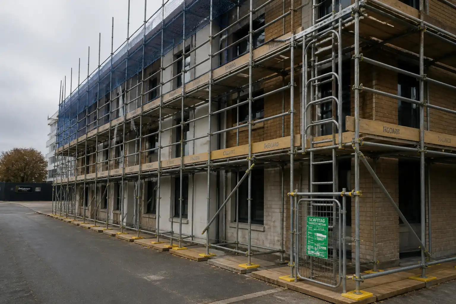
This method statement covers planning, design interface, foundation preparation, erection, tying, bracing, decking, guardrails and toeboards, access ladders/gates, debris containment (where required), inspection tagging, load posting, routine inspections, and handover certification for independent tube-and-fitting scaffolds used for façade construction/maintenance works.
Inclusions
- Temporary works coordination and design interface.
- Ground/sole board preparation and base plate installation.
- Progressive erection of standards, ledgers, transoms, bracing, and ties to the permanent structure.
- Installation of scaffold boards, guardrails, mid-rails, toe boards, brick guards/netting as specified.
- Provision of access ladders with ladder gates or stair towers (if specified by design).
- Anchor selection, installation, and site proof-testing for scaffold ties.
- Inspection regime, tagging (green/yellow/red), load signage, and handover certification.
- Routine inspections (weekly or per local regulation), after alteration, after adverse weather, and after impact events.
Exclusions
- Mechanical hoists, passenger/goods lifts, or mast climbers (unless specifically noted in design).
- Full enclosure shrink-wrap systems (beyond debris netting and sheeting stated in materials).
- Scaffolding to be erected within energized exclusion zones without separate permit and utility coordination.
Assumptions
- Tube-and-fitting independent façade scaffold, service Load Class typically 3 (2.0 kN/m² UDL) [Verify per project specifications].
- Ties provided to the permanent works using approved anchors or structural details, in accordance with the temporary works design.
- Working hours and public interface controls per project permits and traffic/pedestrian management plans.
References
| Document Type | Reference / Number | Revision | Notes |
|---|---|---|---|
| Standard | BS EN 12811-1 | ||
| Standard | BS EN 39 | ||
| Standard | BS EN 74 | ||
| Standard | BS 2482 | ||
| Standard | BS 8539 | ||
| Standard | BS 5975 | Temporary works procedures, design check categories. | |
| Guidance | TG20 [Verify local equivalence] | Use or local equivalent where applicable. | |
| Guidance | SG4 [or local equivalent] | Advance guardrail/collective protection methods. | |
| Standard | EN 131 | ||
| Standard | ISO | ||
| Project Docs | Verify all project-specific values. |
Responsibilities
| Role | Responsibility | Name / Party |
|---|---|---|
| TWC | Contractor | Main Contractor |
| TWD | Design Consultant/Scaffold Contractor | Specialist |
| Site Manager | Main Contractor | Main Contractor |
| Supervisor | Scaffold Contractor | Scaffold Contractor |
| Operative | Scaffold Contractor | Scaffold Contractor |
| Inspector | Main Contractor or Specialist | Appointed |
| HSE | Main Contractor | Main Contractor |
| QA/QC | Main Contractor | Main Contractor |
Resources
| Resource Type | Description | Quantity | Remarks |
|---|---|---|---|
| Manpower | 4–8 certified scaffolders incl. 1 Supervisor (CISRS Advanced or equivalent). | As per program | |
| Manpower | Controls exclusion zone during lifting/hoisting of materials. | 1 | |
| Manpower | On-site first aid support during works. | 1 |
Materials
| Material | Specification / Grade | Quantity | Remarks |
|---|---|---|---|
| S355 or per supplier | As per design | ||
| As per design | |||
| As required | |||
| C16 | As required | ||
| As required | |||
| Per tie schedule | |||
| As required | |||
| As required | |||
| As required | |||
| Per access |
Equipment
| Equipment | Capacity / Type | Quantity | Inspection Required |
|---|---|---|---|
| 2 | Yes | ||
| 2 | Yes | ||
| 1 | Yes | ||
| 1 set | Yes | ||
| Set | Yes | ||
| Per person | Yes |
Prerequisites
- Approved scaffold design/compliance sheet, including tie schedule, anchor type, design tie load, working load class, lift heights, platform widths, bracing, and sheeting/netting requirements.
- Temporary Works Register entry with design category and check completed (BS 5975). Permit to Erect/Load as applicable.
- Ground assessment: verify Safe Bearing Capacity (SBC) and surface preparation. Where uncertain, conduct plate load test or use geotechnical data. Provide sole board sizing calculation.
- Service avoidance: scan and mark underground services near base locations; confirm no façade MEP services or post-tensioning at proposed anchor locations. Where risk exists, use radar/ferroscan and obtain designer approval.
- Material inspection: reject bent, cracked, heavily corroded, or uncertified components.
- Calibrations in date for torque wrenches and pull-test equipment.
- Exclusion zone and access control plan; method for material hoisting (gin wheel or controlled lifts).
- Toolbox talks: SG4-compliant erection methods, manual handling, anchor installation per BS 8539, and emergency rescue plan.
- Weather monitoring: define stop-work triggers [e.g., sustained wind >12 m/s for handling long tubes; sheeting work stop >10 m/s] [Verify per project HSE plan].
- Coordination with façade trades and public protection measures (fans/hoardings/covered walkways) where required.
Method Sequence
| Step | Activity | Description | Responsibility | Inspection / Hold Point |
|---|---|---|---|---|
| 1 | Pre-start coordination and permits | Review design, tie plan, and loading class; brief crew; establish exclusion zone with barriers and signage; issue Permit to Erect (if used). | TWC / Site Manager | |
| 2 | Ground preparation & soleboards | Clear loose material; level and compact as needed. Place sole boards sized per calc; position base plates/adjustable jacks centrally. Verify bearing pressure ≤ allowable SBC. | Scaffold Supervisor | Visual and level check |
| 3 | Erect first lift (standards, ledgers, transoms) | Assemble initial bay(s) to first lift height per design (typically 2.0 m). Install ledger and façade bracing. Plumb and level using clamps; torque couplers to 50 ±10 Nm [Verify]. | Scaffold Crew | Plumb/level |
| 4 | Install first ties | Install ties to the permanent works in accordance with tie schedule (e.g., not exceeding 4.0 m x 4.0 m grid for Class 3) [Verify]. Use specified anchors or through/box ties. Do not exceed edge distances/anchor embedment. Protect façades as required. | Scaffold Crew (trained) | Witness anchor install |
| 5 | Deck the first lift and edge protection | Install scaffold boards with correct spans (≤1.2 m unless otherwise marked). Fix guardrails (top 1.0–1.2 m) and mid-rails; fit toe boards ≥150 mm. Limit façade gap ≤225 mm or fit inner guardrail. | Scaffold Crew | Visual and tape check |
| 6 | Provide access ladder and gate | Install EN 131 ladder at 65–75° (approx. 1:4); extend ≥1.0 m above landing; secure at top and intermediate points; fit self-closing ladder gate. Provide landings at each lift or as designed. | Scaffold Crew | Ladder tie check |
| 7 | Progressive erection of upper lifts | Repeat standards/ledgers/transoms per lift. Maintain bracing per design (ledger and façade bracing). Install ties progressively so that un-tied cantilevers/heights are not exceeded. Install platforms and edge protection at each completed lift. | Scaffold Crew | Progress checks |
| 8 | Install debris netting/sheeting (if required) | Fix netting/sheeting from safe platforms; use specified ties at spacing per manufacturer; provide additional rakers/ties if wind loading requires as per design. | Scaffold Crew | Fixing pattern check |
| 9 | Final checks and snagging | Verify verticality, levels, bracing, ties, decks, edge protection, access, toe boards, ladder gates, striking hazards, and load signage. Clear loose items and install kickers/brickguards where specified. | Scaffold Supervisor | Walkdown |
| 10 | Initial independent inspection and tagging | Competent Scaffold Inspector performs statutory inspection before first use; complete tag at main access (green if safe for use; yellow if restrictions; red if unsafe). | Scaffold Inspector | Formal inspection |
| 11 | Handover certification | Issue handover certificate to Main Contractor confirming scaffold built to design and safe for intended duty and access routes. | Scaffold Supervisor/Inspector | Document review |
| 12 | Routine inspections and maintenance | Weekly inspections (or per local regulation), after alteration, adverse weather, or impact. Maintain records. Update tags after each inspection. Repair/replace damaged components immediately. | Scaffold Inspector / Supervisor | Scheduled |
Health & Safety Controls
Principal Hazards and Controls
- Hazard: Falls from height during erection.
- Likely consequence: Serious injury or fatality.
- Engineering/procedural controls: Use SG4-compliant methods (advance guardrail or collective protection); maintain clipped-on 100% tie-off with double lanyards when outside protected zones; install platforms and guardrails progressively; ladder gates at all access points.
- Required PPE: Full body harness EN 361; double lanyards EN 355; helmet with chinstrap EN 397; gloves; safety boots.
- Collective measures: Guardrails, mid-rails, toeboards, debris netting/brick guards.
-
Inspection/permit/supervision: Daily supervisor checks; pre-use harness checks; formal inspections before first use and weekly; Permit to Erect/Load; competent supervision.
-
Hazard: Scaffold instability/collapse due to inadequate foundations or ties.
- Likely consequence: Collapse causing multiple injuries.
- Engineering/procedural controls: Ground bearing verification and sole board sizing; install ties/bracing per design; do not exceed un-tied height; coupler torque 50 ±10 Nm [Verify]; never remove ties without TWC authorization.
- PPE: Standard PPE.
- Collective measures: Exclusion zones with barriers and tags; no unauthorized access during erection.
-
Inspection/permit/supervision: Hold points at first lift/ties and before handover; torque spot checks; weekly inspection.
-
Hazard: Falling objects (tools, fittings, boards).
- Likely consequence: Head injuries to persons below.
- Engineering/procedural controls: Toe boards, brick guards, debris netting; tether tools where practicable; material hoisting by gin wheel with tag line; prohibit throwing of materials; install toe-kicks on all lifts being worked.
- PPE: Helmets with chinstraps; safety eyewear.
- Collective measures: Demarcated exclusion zone below workface; debris chutes where applicable.
-
Inspection/permit/supervision: Supervisor enforces exclusion; periodic audits.
-
Hazard: Contact with live overhead lines or building services.
- Likely consequence: Electrocution or arc flash.
- Engineering/procedural controls: Identify and isolate or establish exclusion distances (e.g., ≥3 m LV; ≥6 m HV) [Verify per utility owner/local regs]; use non-conductive handling aids where needed; appoint Permit to Work near services.
- PPE: Dielectric gloves where specified; standard PPE.
- Collective measures: Physical barriers and signage to prevent encroachment.
-
Inspection/permit/supervision: Utility permits; continuous supervision when operating near limits.
-
Hazard: Manual handling of tubes/boards and awkward postures.
- Likely consequence: Musculoskeletal injuries.
- Engineering/procedural controls: Team lifts; limit single-lift weights [e.g., <25 kg]; use staging points; hoist materials with certified gin wheel.
- PPE: Gloves; boots.
- Collective measures: Pre-staging racks at ground level.
-
Inspection/permit/supervision: Ergonomic TBT; supervision of lifts.
-
Hazard: Adverse weather (high wind, lightning, heavy rain).
- Likely consequence: Loss of control, slips, structural overload with sheeting.
- Engineering/procedural controls: Monitor wind with anemometer; cease handling long tubes >12 m/s; stop sheeting install >10 m/s; evacuate scaffold during lightning; reassess ties after storms.
- PPE: Weather-appropriate non-slip footwear; rainwear.
- Collective measures: Close scaffold if unsafe; red tag if required.
-
Inspection/permit/supervision: Post-event inspection by competent person.
-
Hazard: Drilling and installing anchors.
- Likely consequence: Striking rebar/services; dust inhalation; poor anchor performance.
- Engineering/procedural controls: Scan for services/rebar where risk exists; use drilling stoppers; dust extraction; install per BS 8539 & manufacturer; carry out proof tests (5% or min 5 anchors) to 1.25× design tie load [Verify].
- PPE: Eye/ear protection; FFP2/FFP3 RPE as needed; gloves.
- Collective measures: Exclusion zone for drilling dust/noise.
-
Inspection/permit/supervision: Anchor installation supervision; calibrated pull-tester; record keeping.
-
Hazard: Public interface and traffic.
- Likely consequence: Injury to third parties.
- Engineering/procedural controls: Hoardings, covered walkways, crash decks where required; schedule high-risk activities during low footfall; traffic marshals.
- PPE: High-visibility clothing.
- Collective measures: Physical segregation and signage.
- Inspection/permit/supervision: Local authority permits; daily checks.
[Verify per project HSE plan and local regulations]
Environmental Controls
- Dust and silica during drilling: Use on-tool dust extraction or wet methods; FFP2/FFP3 RPE; damp wipe down after works; avoid uncontrolled discharge.
- Noise/vibration: Select low-vibration drills; schedule noisy works within permitted hours; provide hearing protection; maintain equipment.
- Waste management: Segregate scrap metal, damaged timber boards, and packaging; dispose via licensed carriers; maintain waste transfer notes.
- Timber sustainability: Source timber with certified chain-of-custody [e.g., FSC/PEFC] where required.
- Chemical anchors: Store resins in secondary containment; follow SDS; prevent spills; use drip trays; dispose of empty cartridges as per local regulation.
- Water and stormwater: Prevent slurry or silt entering drains; cover stockpiles; no washing out on unprotected ground.
- Visual/oversail impacts: Keep scaffold lines neat; remove surplus materials; maintain sheeting integrity to prevent windblown litter.
- Energy and idling: Minimize generator use; switch off equipment when not in use.
[Verify per project environmental plan and local regulations]
Quality Assurance & Quality Control
Key Quality Requirements
- Conformance to the approved scaffold design/TG20 compliance sheet (or local equivalent) and this method statement.
- Materials certification and condition records (tubes, couplers, boards, anchors, netting, ladders).
- Coupler torque control: 50 ±10 Nm [Verify per manufacturer]; log spot checks per lift and per bay sample.
- Foundations: Bearing pressure calculation demonstrates base reactions ≤ allowable SBC; sole boards sized accordingly; record base levels (±10 mm per bay).
- Verticality/Line: Standards within 1:200 verticality; ledgers level across bays within ±10 mm; consistent bay sizes per design.
- Platforms: Board span ≤1.2 m (unless marked for greater span); overhang 50–150 mm; gaps ≤25 mm; façade gap ≤225 mm or provide inner guardrail.
- Ties/Anchors: Install per BS 8539 and manufacturer; maintain tie density/pattern; proof-test 5% (min 5) of installed anchors or as per design; test load typically 1.25× design tie load with residual displacement ≤2 mm and no creep [Verify per design/manufacturer].
- Edge Protection: Guardrail top height 1.0–1.2 m; mid-rail at mid-height; toeboards ≥150 mm; brick guards where specified.
- Ladders: EN 131; pitch 65–75°; extend ≥1.0 m above landing; tied; ladder gate installed.
- Sheeting/Netting: Fixing pattern per manufacturer; check additional ties/bracing per design due to wind loading.
- Tagging/Signage: Tag at primary access; post duty class and UDL (e.g., Class 3: 2.0 kN/m²) and bay-specific restrictions [Verify per design].
Hold and Witness Points
- H1 (Hold): First lift erected and primary ties installed—inspection prior to proceeding above.
- H2 (Hold): Anchor proof test results accepted by TWC/TWD.
- H3 (Hold): Final inspection prior to handover/tagging.
- W1 (Witness): Coupler torque spot checks; ladder installation; bracing pattern checks.
Records
- Material delivery/inspection logs; torque logs; anchor installation and pull-test reports; scaffold inspection registers; handover certificate; permits; TBT records; calibration certificates.
Nonconformities
- Record NCRs for out-of-tolerance items (e.g., missing ties, inadequate edge protection, failed anchors). Rectify, re-inspect, and close NCR with evidence.
Attachments
- Approved scaffold design drawings and/or TG20 compliance sheets [Verify local equivalent].
- Temporary Works Register entry and design check certificate.
- Sole board sizing and bearing pressure calculation sheet.
- Anchor schedule, manufacturer’s data sheets, and pull-test plan/results.
- Coupler torque check log template.
- Scaffold pre-handover checklist and handover certificate template.
- Scaffold inspection register (weekly) and tagging procedure.
- Risk Assessment and COSHH/SDS for chemical anchors (if applicable).
- Toolbox talk materials: SG4 methods, manual handling, anchor installation, rescue plan.
- Permit to Work near services/overhead lines (if applicable).
This content is a read-only public reference. Download or customize to get an editable version.
ITP preview
The first inspection activities from the linked ITP for Method Statement: Independent Scaffold Erection for Façade Construction Works:
| Activity | Inspection / Test | Acceptance Criteria | Responsibility | Record |
|---|---|---|---|---|
| Design and permits review | Check approvals | Approved scaffold design/compliance sheet; TW register entry; Permit to Erect/Load as applicable. | TWC / QA | Approved drawings; TW register; permit |
| Ground bearing and sole boards | Check calc vs SBC | Bearing pressure ≤ allowable; base level ±10 mm per bay; correct sole board size. | Scaffold Supervisor / QA | Pre-erection checklist; calc sheet |
| First lift erection (standards/ledgers/transoms) | Torque spot checks | Verticality within 1:200; coupler torque 50 ±10 Nm [Verify]. | Scaffold Supervisor / QA | Torque log; inspection sheet |
Showing 3 of 11 inspection activities. View full ITP →
Related Inspection and Test Plan
An Inspection and Test Plan (ITP) is available for Method Statement: Independent Scaffold Erection for Façade Construction Works. The ITP defines the inspection activities, acceptance criteria, hold and witness points, responsible parties, and records required to verify the work described in this method statement.
View the Method Statement: Independent Scaffold Erection for Façade Construction Works ITP →Frequently asked questions
Continue with related Quollnet resources connected to this method statement.