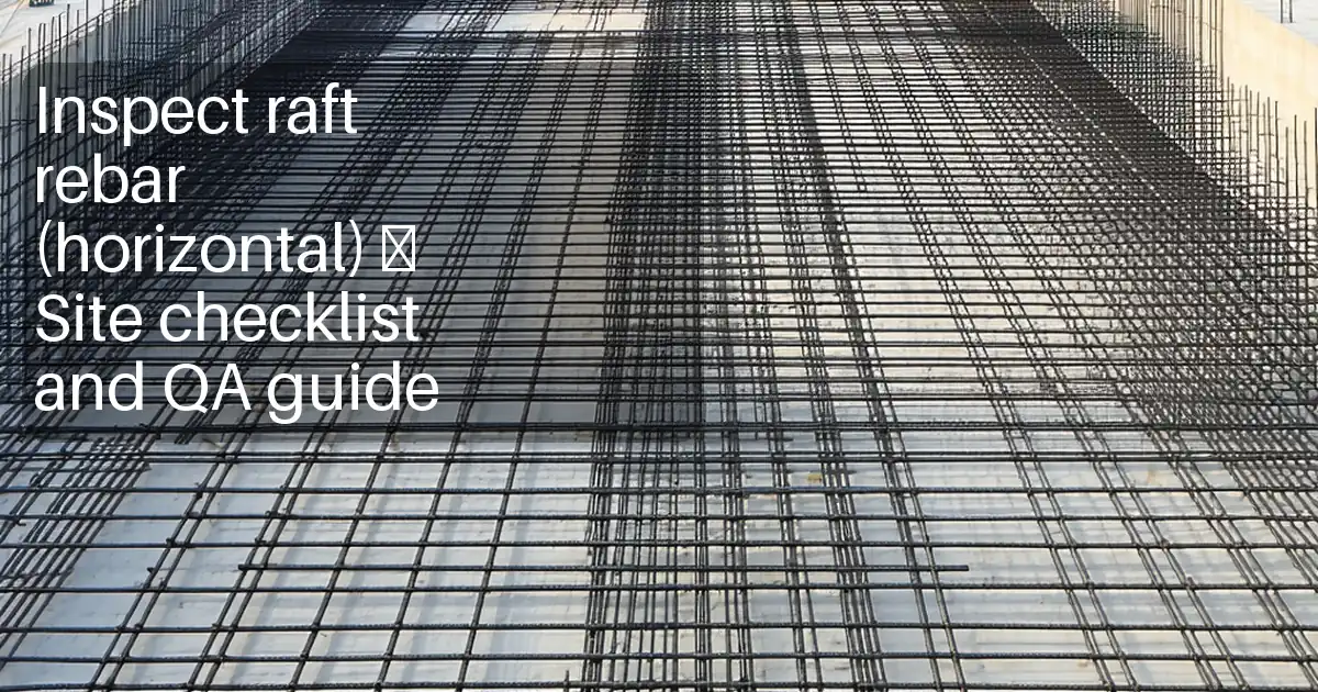
Inspect retaining wall footing reinforcement (horizontal)
Definition: Inspect retaining wall footing reinforcement (horizontal) is a field checklist for site engineers to verify bar sizes, spacing, cover, lap splices, and dowels before placement activities, excluding any concrete testing or concreting operations.
- Confirm bar diameters, spacing, and cover match approved drawings and schedules.
- Reduce rework by catching misaligned laps, missing chairs, or wrong dowels early.
- Use calibrated tools to measure, photograph, and document acceptance evidence.
- Interactive, commentable checklist with export and QR code traceability.
Inspect retaining wall footing reinforcement (horizontal) is a critical pre-pour task that validates the rebar layout against the approved drawings and schedules. This checklist focuses on horizontal reinforcement within the footing, including bar sizes, spacing, lap splices, bar cover, supports, and the dowels that connect the footing to the wall stem. It excludes concrete-related controls and tests, keeping the scope clearly on steel placement and documentation. By verifying the reinforcement schedule, confirming chairs and spacers, checking dowel alignment, and measuring laps with a tape or rebar gauge, you prevent under-reinforcement, bar corrosion from inadequate cover, and stem misalignment due to misplaced dowels. The outcome is a compliant installation ready for form closure and further inspections, backed by photo evidence, material identification, and sign-offs per approved project specifications and authority requirements. Use this interactive checklist in the field: tick each item, add comments for nonconformances, and export your record as PDF or Excel with a QR code for authentication.
- Validate footing rebar against approved drawings and bar schedules, confirming bar diameters, spacing, cover, laps, and dowels. Catch errors early to avoid costly rework, schedule delays, and future durability issues such as corrosion or cracking from inadequate cover.
- Provide defensible evidence with calibrated measurements, photos, and material tags. Record bar gauges, lap tape readings, cover block thickness, dowel alignment checks, and approvals, ensuring traceability per approved project specifications and authority requirements.
- Interactive online checklist with tick, comment, and export features secured by QR code. Field teams capture findings in real time, supervisors resolve issues on the spot, and stakeholders receive authenticated PDF/Excel reports for records and audits.
- Improve constructability by verifying chair types and spacing, tie patterns, lap staggering, and dowel embedment before closing formwork. This reduces congestion, prevents bar movement during handling, and ensures the stem interface is in the correct location.
Documentation & Identification
Bar Sizes & Spacing (Horizontal)
Cover & Supports
Laps & Anchorage
Dowels to Stem Interface
Placement, Tying & Restraint
Get bar sizes, spacing, and laps correct the first time
Accurate horizontal reinforcement begins with confirming bar marks, diameters, grades, and spacing directly against the approved drawing and schedule. Use a rebar gauge or vernier calipers to verify nominal diameters, and photograph readings in millimetres next to bar marks for traceability. Lay out spacing with chalk lines and a steel tape; mark reference stations to catch cumulative errors along long footings. For lap splices, mark lap start and end with a paint marker, then record measured length with a tape. Stagger laps as shown to avoid congestion and weak planes. Where hooks or step/heel details appear, measure hook or embed lengths against the schedule. Keep all evidence in the checklist with comments for any deviation. Early detection of wrong bar size, incorrect spacing, or short laps prevents structural deficiencies and avoids cutting out steel after form closure. Always align field decisions with the approved project specifications and authority requirements.
- Gauge and photograph bar diameters in millimetres.
- Set spacing with chalk lines and a steel tape.
- Mark and measure lap lengths; record photos.
- Stagger laps to match drawing intent.
- Document deviations and approvals immediately.
Reliable cover and support: durability starts here
Adequate bar cover protects reinforcement from corrosion and ensures bond performance. Select approved spacers or chairs suited to bar size and exposure conditions, then verify their thickness equals the specified cover (often stamped, such as 50 mm). Place spacers at the correct centres and check that bars do not rock or shift under light handling. Measure soffit and edge cover from formwork to the nearest bar with a ruler or cover meter and photograph the readings. Orient tie wire tails away from cover faces to prevent encroachment, and use non-metallic spacers where faces will remain exposed to avoid staining. Keep the mat free of debris that might hold bars off the chairs. Target a consistent, repeatable layout rather than spot fixes. Acceptance should always be against the drawings, manufacturer data, and the approved project specifications and authority requirements.
- Use stamped spacers matching specified cover.
- Measure soffit and edge cover from formwork.
- Stabilize bars; prevent rocking or shift.
- Keep tie tails clear of cover faces.
- Avoid debris that alters bar position.
Dowel alignment and interface with the wall stem
Dowels link the footing to the retaining wall stem, so their size, alignment, embedment, and projection must be correct. Start by verifying dowel diameter and grade using a gauge and marking legend. Measure embedment into the footing and the projection above the top of reinforcement to ensure the stem steel will seat at the correct elevation. Use a plumb line or spirit level for verticality and string line for centerline alignment along the wall axis. Where hooks or couplers are specified, confirm orientation and identification. Install protective caps until the stem assembly begins to prevent hazards and bending. If dowels deviate, raise a comment with measured offsets and proposed correction for approval before proceeding. All checks are against the drawings and per approved project specifications and authority requirements.
- Gauge dowel size and confirm grade.
- Measure embedment and projection in millimetres.
- Check verticality with plumb/level tools.
- Align along centerline using a string line.
- Protect exposed dowels with caps.
How to use this checklist in the field
- Preparation: bring drawings/schedules, rebar gauge or calipers, steel tape, marker, plumb line/level, cover meter or ruler, camera, PPE (gloves, eye protection, boots), and QR-enabled device.
- Open the interactive checklist on your device, select project, location, and footing segment, and confirm the latest revisions are loaded.
- Work item-by-item: measure, photograph evidence, and tick completed checks. Add comments with dimensions, bar marks, and tag numbers for any nonconformance.
- Use the comment threads to assign actions to fabricators or foremen, attach markup photos, and set due dates for corrections.
- When resolved, retake measurements and photos, close comments, and re-tick items to show compliance per approved project specifications and authority requirements.
- Export the completed record to PDF/Excel, including embedded photos and measurements. The export includes a QR code for authentication.
- Sign-off: capture digital signatures from the inspector and contractor representative, distribute to stakeholders, and archive within the project record.

Call to Action
- Start Checklist Tick off tasks, leave comments on items or the whole form, and export your completed report to PDF or Excel—with a built-in QR code for authenticity.
- Download Excel - Retaining Wall Footing Rebar Inspection (Horizontal)
- Download PDF - Retaining Wall Footing Rebar Inspection (Horizontal)
- View Image - Retaining Wall Footing Rebar Inspection (Horizontal)
Cite & Embed
“Retaining Wall Footing Rebar Inspection (Horizontal) by Quollnet”
with a link to
this source page.
FAQ
Question: How do I verify bar diameter if factory markings are missing or hard to read?
Question: What if the specified cover does not match the available spacer thickness on site?
Question: How can I measure lap splice length accurately in a congested mat?
Question: Is light rust acceptable on reinforcement before inspection?
Question: What should I do if dowels are misaligned relative to the wall centerline?
Related Articles
Broader reading and guidance connected to this checklist topic.


Is It Important To Customize Your Qr Code And How To Do It?
Is The Crack You See On Your Wall Serious Or Minor Cosmetic Issue?

Master Construction Project Cashflow With Cashflowpot
Related Checklists
Keep the workflow moving with nearby templates chosen from similar checklist content.