Retaining Wall Stem Reinforcement (Vertical) Inspection Checklist
Definition: Retaining wall stem reinforcement (vertical) inspection ensures vertical rebar spacing, cover, laps, and openings comply, guiding site engineers, foremen, and inspectors before concrete placement while explicitly excluding concreting activities.
- Verify bar layout, sizes, spacing directly against approved drawings.
- Measure concrete cover with covermeter; confirm chairs and spacers.
- Check lap splices, couplers, and around openings for compliance.
- Interactive, commentable checklist with export and QR code verification.
Retaining wall stem reinforcement (vertical) inspection confirms the vertical rebar is installed to the approved drawings before any concrete is placed. This focused checklist supports vertical rebar checking, retaining wall steel fix inspection, and bar spacing and cover checks on the stem only, excluding concreting. You will verify bar sizes and spacing, concrete cover using spacers and a covermeter/template, lap splice lengths or couplers, and detailing around openings and embedded items. By capturing measurements, photos, and approvals, you reduce risks of inadequate cover, misaligned bars, insufficient development, congestion at openings, and costly rework. The outcome is a compliant, durable stem that accepts formwork and subsequent concreting without clashes, while meeting the approved project specifications and authority requirements. Use this as a hold‑point inspection: measure, mark any corrections, and record evidence for quality assurance. Start the interactive mode to tick items, leave comments for the steel fixer, and export your completed record to PDF/Excel with a secured QR code.
- This checklist structures pre‑pour verification for vertical stem reinforcement, focusing on spacing, cover, laps, and openings. It directs inspectors to compare against approved drawings, record actual measurements, and attach photos, ensuring traceable evidence before formwork close‑out and any concrete works, while maintaining a clear, repeatable process for crews and supervisors.
- By emphasizing measurable tolerances, stable support, and documented identification of bar grades, it reduces durability risks from insufficient cover, prevents congestion near openings, and protects structural performance by confirming development lengths, lap staggering, and coupler engagement. The result is higher first‑time quality and reduced rework and delays.
- Designed for busy sites, the steps specify tools like steel tapes, plumb lines, covermeters, and templates. Each instruction demands acceptance cues or sign‑offs, enabling quick go/no‑go decisions. Integrated photo evidence and batch/heat number capture strengthen audit readiness and demonstrate compliance with approved project specifications and authority requirements.
- Interactive online checklist with tick, comment, and export features secured by QR code.
Documents & Layout
Rebar Materials & Identification
Vertical Bar Spacing & Alignment
Concrete Cover & Spacers
Laps, Couplers & Anchorage
Openings, Penetrations & Embedded Items
Getting spacing and alignment right on the stem
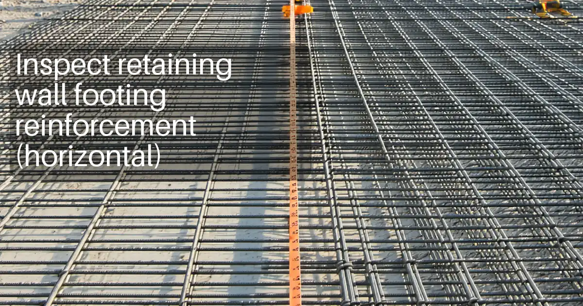
Accurate vertical bar spacing and plumb alignment drive constructability and performance. Begin by locking in the latest drawings and marking centrelines at the specified pitch along the stem. Use a tape and chalk line to establish a visual guide, then measure actual bar‑to‑bar spacing at intervals. A plumb line or spirit level shows whether bars are truly vertical, which preserves cover at both faces. Record edge distances at corners and returns because these govern crack control and exposure durability. Bar congestion often begins where mis‑spaced starters meet new bars; maintaining clear gaps avoids vibration difficulties later. Capture readings in millimetres and back them with photos showing a scale. If a reading falls outside tolerance, tag the location, instruct the fixer, and re‑measure after correction. Keep evidence with chainage or grid references for traceability. Finally, confirm projections at steps or joints achieve the specified development so the wall stem connects continuously across discontinuities without overstressing the lap zone.
- Measure spacing at multiple locations per inspection bay.
- Use plumb line or spirit level for verticality checks.
- Record corner edge distances exactly as detailed.
- Tag out‑of‑tolerance bars and re‑verify corrections.
- Capture photos with a visible measurement scale.
Assuring specified cover with the right supports
Concrete cover is your primary durability control. Select non‑absorbent spacers or compatible concrete blocks that match the specified cover and can carry fresh concrete loads without crushing. Place them at the frequency stated in the approved specifications, increasing density at corners, edges, and openings. Before formwork close‑out, use a rigid template or cover gauge to confirm the distance from the formed face to the bar. Where future access is tight, pre‑plan spacer locations so they do not clash with ties or embedded items. Keep tie‑wire tails bent away from the cover zone and trim sharp ends to prevent formwork damage and rust staining. Temporary bracing should resist bumps during formwork installation, preventing displacement that would reduce cover. Photograph typical placements, product labels, and measurement readings. If a spacer type differs from the submittal, pause and obtain approval before proceeding—consistency protects both quality and records.
- Match spacer type and height to specified cover.
- Use templates to measure cover before close‑out.
- Densify supports at corners and openings.
- Trim and orient tie‑wire tails away from cover.
- Photograph placements and retain product datasheets.
Managing laps, couplers, and reinforcement around openings
Lap splices and couplers sustain load continuity in the stem. Measure laps with a tape, mark the start and end with paint, and log the total millimetres against the drawing. Stagger splices to avoid a single plane of weakness. For mechanical couplers, verify the correct type and full engagement; photograph witness marks and record batch numbers for traceability. At openings, ensure bars are shifted as detailed so cover is maintained, then confirm additional trimmer bars and anchorage lengths are present and tied. Check sleeves and embedded items are fixed with the minimum clearance from reinforcement, eliminating contact that can cause vibration blockages and honeycombing later. When the stem steps in height, validate that development is preserved across the step with laps or couplers per the details. These targeted checks reduce repair risks and help demonstrate conformity to the approved project specifications and authority requirements.
- Measure and mark lap splice start and end.
- Stagger splices per drawings to avoid congestion.
- Confirm coupler type, engagement, and batch records.
- Maintain cover while shifting bars around openings.
- Keep sleeves clear of reinforcement by specified distance.
How to use this interactive vertical stem reinforcement checklist
- Preparation: gather approved drawings/BBS, steel tape, vernier caliper, plumb line/spirit level, cover gauge/template, chalk line, tags/paint, PPE, and a mobile device with camera. Confirm access is safe and the area is clean and well lit.
- Open the checklist in interactive mode. Select the location (grid/chainage and elevation), then proceed item by item, measuring and photographing evidence as requested.
- For each check, enter actual readings in SI units, attach photos of scales/tags, and note any variances against approved project specifications and authority requirements.
- Use comments to assign actions to the steel fixer or foreman, set due times, and tag corrective areas directly on photos for clarity.
- When all items pass, generate the report and export to PDF/Excel. Ensure the QR code appears for authentication and link‑back to source records.
- Sign‑off: capture digital signatures from inspector and contractor’s representative, distribute to stakeholders, and archive with project references for traceability.

Call to Action
- Start Checklist Tick off tasks, leave comments on items or the whole form, and export your completed report to PDF or Excel—with a built-in QR code for authenticity.
- Download Excel - Retaining Wall Stem Reinforcement Inspection (Vertical)
- Download PDF - Retaining Wall Stem Reinforcement Inspection (Vertical)
- View Image - Retaining Wall Stem Reinforcement Inspection (Vertical)
Cite & Embed
“Retaining Wall Stem Reinforcement Inspection (Vertical) by Quollnet”
with a link to
this source page.

FAQ
Question: What tolerances should I apply for vertical bar spacing and plumb?
Question: How do I verify concrete cover before pouring when the face is not yet closed?
Question: What should I check for mechanical couplers on vertical stem bars?
Question: How do I handle reinforcement around openings without losing cover?
Related Articles
Broader reading and guidance connected to this checklist topic.


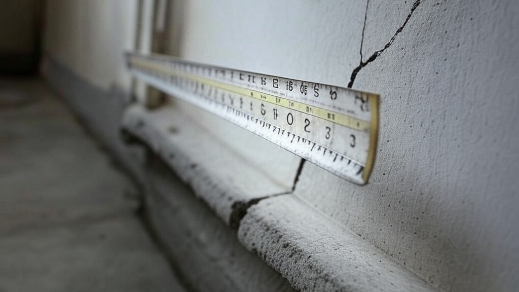
Is The Crack You See On Your Wall Serious Or Minor Cosmetic Issue?


Related Checklists
Keep the workflow moving with nearby templates chosen from similar checklist content.