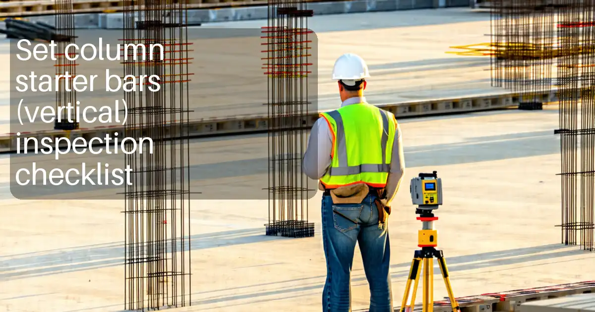
Expose Starter Bars Inspection Checklist and Field Guide
Definition: Expose starter bars inspection guides site engineers to verify lengths, spacing, integrity, and protection of vertical bars during exposure; coupler installation is excluded.
- Confirm protrusion length, spacing, and verticality against approved drawings on site.
- Assess bar integrity: bends, nicks, corrosion, and base condition; document with photos.
- Apply caps and temporary corrosion protection to prevent injury and deterioration.
- Interactive, commentable checklist with export and QR code for authenticated records.
Expose starter bars inspections help ensure vertical reinforcement revealed from concrete is ready for continuity work. This checklist focuses on vertical projecting rebar—often called starter reinforcement or protruding bars—emerging from slabs and footings to connect future walls and columns. It excludes coupler installation activities. You will confirm protruding lengths, bar spacing, verticality, and bar diameter against the approved drawings; evaluate integrity for damage, bends, arc burns, or corrosion; and verify protection such as high‑visibility caps and temporary corrosion control. Proper exposure and verification reduce structural risks from insufficient development length, misalignment, or hidden damage, and prevent injuries from uncovered bar ends. The outcome is a safely managed workfront with traceable measurements, clear photo evidence, and ready-to-build status per approved project specifications and authority requirements. Use this interactive checklist to tick items, add comments with photos, and export your inspection record to PDF or Excel, complete with a QR for authentication.
- This checklist targets vertical starter bars projecting from slabs or footings, verifying protruding length, spacing, verticality, and diameter against approved drawings. It also confirms integrity, base condition at emergence, and adequate temporary protection, while explicitly excluding coupler installation.
- Each step specifies a method and acceptance tolerance, e.g., length −10/+0 mm, spacing ±10 mm, and verticality within 5 mm over 1 m. Photos with scales, annotated plans, and measurement logs create auditable, lot-based evidence aligned to site gridlines.
- Integrity checks cover bends, nicks, arc burns, and corrosion, with practical limits like no section loss over 5% or pitting greater than 0.5 mm. Protective measures include bar-end caps, temporary coatings, and weather-resistant covers to maintain safety and readiness.
- Interactive online checklist with tick, comment, and export features secured by QR code. Capture signatures, assign actions, and archive inspection packs per approved project specifications and authority requirements for streamlined quality assurance and safe handover.
Pre-Exposure Controls
Exposure and Cleaning
Length and Spacing Verification
Integrity and Damage Assessment
Protection and Temporary Measures
Documentation and Handover
Scope, Safety, and Controlled Exposure of Vertical Starter Bars
This checklist covers vertical starter bars projecting from slabs or footings to connect future walls or columns. It begins before physical exposure, ensuring the latest drawings are in hand, hazards are controlled, and a gentle method is selected to avoid damaging reinforcement. Use a cover meter to confirm bar positions, then expose with low-impact tools, keeping at least a small annulus of visible steel at the emergence point. Clean residual laitance and light rust using brushes, not grinders, to preserve bar diameter and rib profile. Check the surrounding concrete for spalls or cracks that might reduce effective embedment. Photograph each location with a scale for later verification. Good planning prevents costly rework, reduces injury risk from protruding bars, and sets up a clean, documented workfront ready for dimensional checks per approved project specifications and authority requirements.
- Confirm latest drawings and grid references before starting exposure.
- Use cover meters and low-impact tools near reinforcement.
- Clean steel with brushes; avoid grinding rib profiles.
- Inspect and photograph base concrete for spalls and cracks.
- Control hazards with exclusion zones and clear signage.
Dimensional Verification: Length, Spacing, Verticality, and Diameter
After exposure, verify protruding length with a steel rule from the finished concrete surface. A practical acceptance is −10/+0 mm on the specified projection, ensuring no shortfall jeopardizes development length. Measure centre-to-centre spacing with a tape against the drawings, targeting ±10 mm. Check verticality using a plumb line or mini level, aiming for a deviation not exceeding 5 mm over a 1 m projection to ensure fit-up with shutters or couplers later (installation excluded). Confirm bar diameter with a caliper or gauge and match to the schedule. Annotate plan prints with measured values, tag each location, and capture photos with a visible scale. Dimensional accuracy at this stage avoids clashes with future reinforcement, ensures correct cover, and yields a traceable record that supports approvals and efficient follow-on works.
- Record length, spacing, and verticality with tools and scales.
- Target −10/+0 mm length and ±10 mm spacing tolerances.
- Keep verticality within 5 mm over 1 m projection.
- Confirm diameter matches the schedule and note mill marks.
- Annotate plans and tag locations for traceability.
Integrity Assessment and Temporary Protection for Safe Readiness
Inspect each bar for damage, including nicks, gouges, arc burns, and unintended bends. Minor bends can be cold-corrected with an approved jig; avoid heat. Accept no section loss beyond 5% and no pitting deeper than 0.5 mm; uniform light rust is generally acceptable. Ensure the base concrete is sound, with no breakout undermining embedment. Fit high-visibility caps immediately to prevent impalement hazards, then apply temporary corrosion protection where exposure is extended or environments are aggressive. Grouped bars should be covered with UV-resistant sheets secured to prevent wind chafing. Maintain housekeeping to avoid trip hazards and material contamination. Log all evidence—photos with scales, measurements, and annotations—in the interactive checklist for review and sign-off per approved project specifications and authority requirements.
- Reject deep pitting or section loss; accept only light surface rust.
- Cold-straighten minor bends with an approved jig; avoid heat.
- Install caps on all bar ends to prevent injuries.
- Apply temporary coatings when exposure extends or environment is harsh.
- Upload photo evidence and measurement logs for sign-off.
How to Use This Checklist On Site
- Preparation: gather approved drawings, cover meter, steel rule, tape, plumb line, caliper, brushes, solvent rags, high-visibility caps, temporary coating, tags, PPE, and camera.
- Open the interactive checklist, select project, location, and lot/pour. Confirm scope is vertical starter bars and that coupler installation is excluded.
- Start inspection in interactive mode: tick items as completed, enter measured values, and attach photos with scales and annotated plan snapshots.
- Use comments to flag issues, assign responsible persons, and set due dates. Reference gridlines and unique tag IDs in each comment for traceability.
- Export progress or final records to PDF/Excel for distribution. The QR code on exports authenticates the dataset and links back to the live checklist.
- Sign-Off: collect digital signatures from inspector and contractor representatives; archive the lot pack and share with stakeholders per project procedures.

Call to Action
- Start Checklist Tick off tasks, leave comments on items or the whole form, and export your completed report to PDF or Excel—with a built-in QR code for authenticity.
- Download Excel - Expose Starter Bars Inspection
- Download PDF - Expose Starter Bars Inspection
- View Image - Expose Starter Bars Inspection
Cite & Embed
“Expose Starter Bars Inspection by Quollnet”
with a link to
this source page.
FAQ
Question: What protruding length tolerance should I apply when inspecting starter bars?
Question: Is light rust acceptable on exposed starter bars, and how should I clean it?
Question: What should I do if a starter bar is bent or has a nick after exposure?
Question: How do I protect exposed bars if follow-on work is delayed?
Question: Can I verify spacing and verticality without specialized equipment?
Related Articles
Broader reading and guidance connected to this checklist topic.


Related Checklists
Keep the workflow moving with nearby templates chosen from similar checklist content.