Method Statement – Reinforced Concrete Pile Cap Construction and Tie-Beam Integration – Method Statement
AI-assisted method statement with matching ITP, PDF download, and Excel export.
More than a static template
Unlike a downloadable Word or PDF template, this method statement is an AI-assisted editable starting point connected directly to a matching Inspection and Test Plan. Every section is structured, project-adaptable, and ready to export.
- AI-assisted drafting — Customize every section with AI for your specific project scope.
- Linked ITP — A matching inspection and test plan is generated alongside the method statement.
- Multiple export formats — Download as a formatted PDF or editable Excel spreadsheet.
- Editable starting point, not a final document — Review, verify, and adjust all content against your project requirements before use.
Static template vs. Quollnet workflow
| Feature | Static template | Quollnet |
|---|---|---|
| Project-specific content | Manual fill-in required | AI-assisted customization |
| Linked ITP | Separate document, no link | Matching ITP included |
| Export formats | Usually PDF only | PDF and Excel |
| Structured sections | Free-form layout | 13 standardized sections |
| Saved to your account | Local file only | Cloud-saved, reusable |
| Content accuracy | You verify everything | AI-assisted, you still verify |
| Cost | Often free but time-intensive | Free to customize and download |
What you can customize
When you save this method statement to your account, every section becomes editable. The following 13 sections are included:
- Scope — Defines the activity and its boundaries.
- References — Standards, specifications, and drawings.
- Responsibilities — Roles and accountabilities.
- Resources — Labour, plant, and equipment summary.
- Materials — Materials and compliance requirements.
- Equipment — Tools and equipment details.
- Prerequisites — Hold points and pre-conditions.
- Method sequence — Step-by-step construction sequence.
- Safety controls — HSE risk controls and PPE.
- Environmental controls — Environmental mitigation measures.
- QA/QC — Quality inspection and test requirements.
- ITP — Inspection and Test Plan table (has its own page).
- Attachments — Referenced drawings and documentation.
Why this method statement is used
This method statement is used to define and communicate the approved procedure for carrying out method statement – reinforced concrete pile cap construction and tie-beam integration on site. It ensures the work is planned in advance, the correct resources and controls are in place, and all personnel understand responsibilities, sequence, quality requirements, and safety controls before work begins. It aligns site execution with the documented scope and acceptance expectations.
Who uses this method statement
This method statement is used by contractors, site supervisors, project engineers, QA/QC engineers, HSE officers, consultants, and client representatives. It serves as a shared reference for planning, execution, supervision, inspection, and approval of the activity on site.
When it is prepared and submitted
The method statement is prepared before the work activity starts and submitted as part of the pre-construction documentation package for review and approval.
Who reviews or approves it
The method statement is usually submitted to the client representative, consultant, resident engineer, or project management consultant for review and approval before the work commences.
Important approval note
This method statement is an AI-assisted editable starting point, not a pre-approved document. Before use on any project, all content must be reviewed and approved by the relevant parties (superintendent, principal contractor, or client representative) in accordance with your contract and project quality plan.
For example: if your specification requires a departure from a referenced standard, that departure must be documented and approved separately — this method statement will not capture that automatically. Always verify against your applicable drawings, specifications, and regulatory requirements.
Method statement content
Scope
Inclusions
- Verification and setting out of pile cap and tie-beam coordinates and levels.
- Controlled excavation (if required) to expose pile heads and cap formation level.
- Pile head chipping/breaking to design cut-off level without damaging reinforcement.
- Preparation for rebar casting-in: cleaning, roughening, doweling/drilling and grouting (if required by design).
- Blinding concrete placement and finishing.
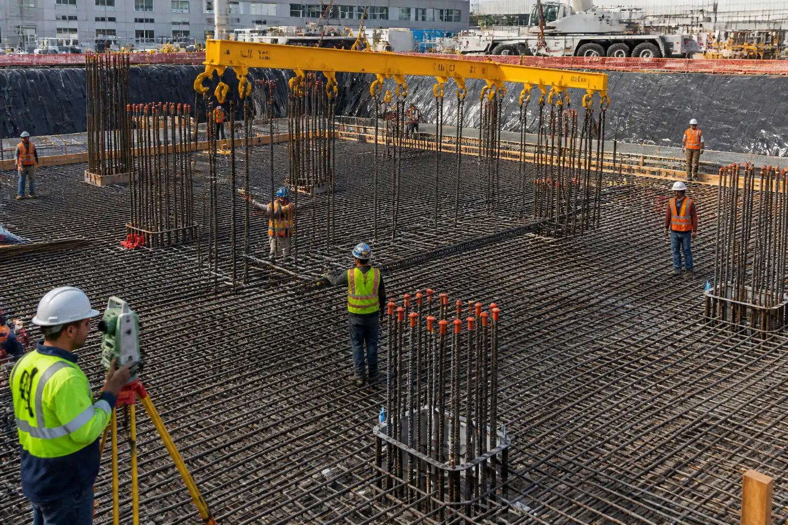
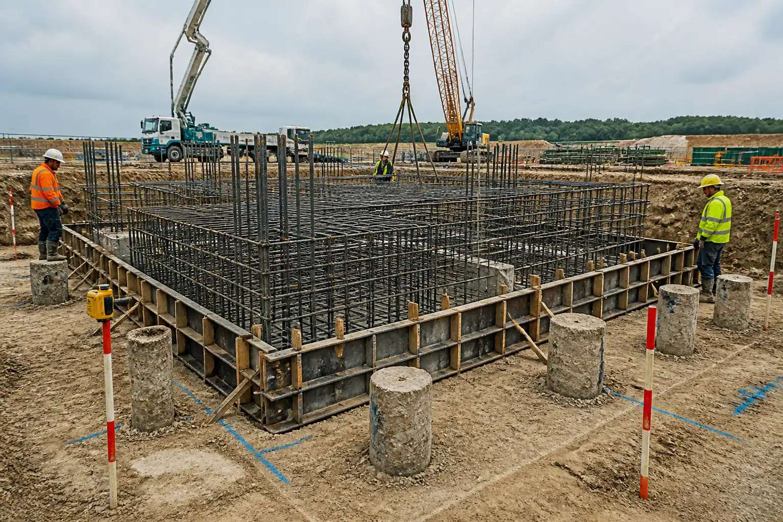
- Fixing of heavy reinforcement for pile cap and integration of tie-beam dowels/starters.
- Formwork/shuttering including chamfers, kicker (if specified), ties, and release agent.
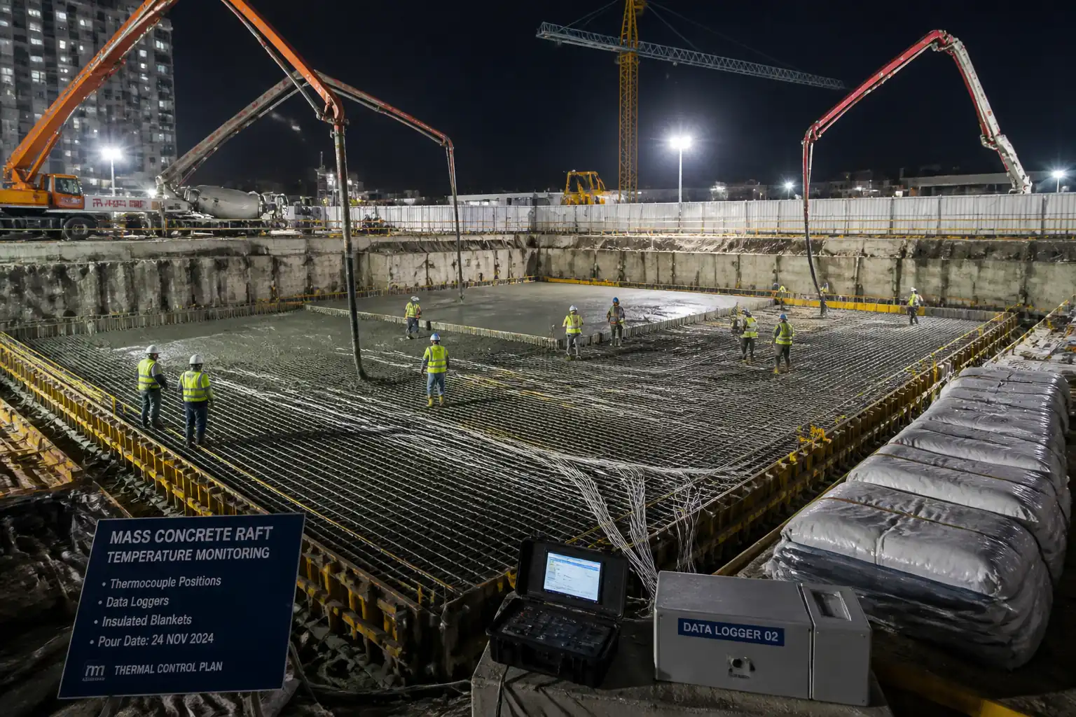
- Concrete production coordination, delivery, placement, vibration, finishing, curing, protection, and formwork striking.
- Monolithic or sequential integration of structural tie-beams with pile caps, including construction joints where specified.
- As-built survey and records; backfilling around pile caps when concrete achieves required strength.
Exclusions
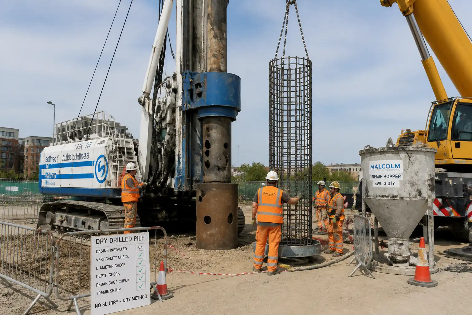
- Pile installation and integrity testing (by others unless stated otherwise).
- Permanent waterproofing systems and membranes unless noted in drawings/specs.
- Ground improvement, temporary works design for deep excavation support (if needed beyond local trimming).
Interfaces
- Structural/Geotechnical Engineer: pile acceptance, cut-off levels, reinforcement details.
- MEP/Civil: embedded conduits, earthing, sleeves or anchor systems within caps.
- QA/QC and Third-party laboratory: material approvals and testing.
- HSE: permits, lifting plans, excavation safety, dewatering management.
References
| Document Type | Reference / Number | Revision | Notes |
|---|---|---|---|
| ACI 318 – Building Code Requirements for Structural Concrete | Design reinforcement, cover, development/splice lengths [Verify per project design]. | ||
| ACI 117 / BS EN 13670 – Concrete construction tolerances / Execution of concrete structures | Dimensional and level tolerances; formwork striking guidance. | ||
| BS EN 206 / ASTM C94 – Specification for concrete | Concrete class, exposure class, delivery, production, conformity assessment. | ||
| BS EN 12350 (Slump/Flow) / ASTM C143 (Slump) / ASTM C172 (Sampling) | Fresh concrete tests. | ||
| BS EN 12390 / ASTM C39 – Compressive strength testing | Cube/cylinder making, curing and testing. | ||
| BS 4449 / ASTM A615 – Reinforcing steel | Grades, ribbed bars, bend radii, mill certs. | ||
| EN 1992-1-1 (Eurocode 2) / EN 1997-1 (Eurocode 7) | Reinforced concrete detailing; geotechnical design considerations for piles and pile caps. | ||
| BS EN ISO 17660 / AWS D1.4 – Welding of reinforcing steel | If welded splices or couplers are used [Verify per project]. | ||
| ACI 305 / ACI 306 – Hot/Cold Weather Concreting | Temperature control, curing adjustments [Verify per project HSE plan and local regulations]. | ||
| BS 8004 – Foundations (Code of practice) | General tolerances for pile locations and cut-off (guidance) [Verify per project]. |
Responsibilities
| Role | Responsibility | Name / Party |
|---|---|---|
| Project Manager | Project Manager | Contractor |
| Construction Manager | Construction Manager | Contractor |
| Land Surveyor | Land Surveyor | Contractor |
| QA/QC Engineer | QA/QC Engineer | Contractor |
| HSE Officer | HSE Officer | Contractor |
| Site Engineer / Foreman | Site Engineer / Foreman | Contractor |
| Engineer/Consultant | Engineer/Consultant Representative | Engineer |
| Laboratory | Third-Party Laboratory | Independent |
Resources
| Resource Type | Description | Quantity | Remarks |
|---|---|---|---|
| Labor | As per BBS [Verify] | ||
| Labor | As required | ||
| Labor | Per pour plan | ||
| Labor | 1 banksman + operator per crane | ||
| Labor | 1 Surveyor + 1 Assistant |
Materials
| Material | Specification / Grade | Quantity | Remarks |
|---|---|---|---|
| Structural concrete for pile caps/tie-beams | Slump 100–160 mm for pumped [Verify]; max W/C ratio per design [Verify]; temperature at discharge 5–32°C [Verify] | Exposure class as per design; target fck [Verify] | |
| Blinding concrete | Class C12/15 to C16/20 [Verify] | Thickness 50–75 mm [Verify] | |
| Reinforcement steel | BS 4449 Grade B500B/C or ASTM A615 Grade 60 [Verify]; Couplers per BS EN ISO 15835 if used | Cover: bottom/sides 75 mm; top 50 mm [Verify] | |
| Spacers, chairs, tying wire | Heavy-duty plastic/FC spacers; 1.6 mm GI tie wire | Chairs per load demand | |
| Anchoring grout/epoxy | ASTM C1107 (non-shrink grout) or ICC-ES approved epoxy [Verify] | Embedment length per design [Verify] | |
| Formwork and release agent | Steel/plywood shuttering, chamfers 20–25 mm; release per manufacturer | VOC-compliant [Verify] | |
| Curing compound / wet burlap | ASTM C309 membrane compound; clean water for wet cure | Where subsequent concrete is not to be bonded |
Equipment
| Equipment | Capacity / Type | Quantity | Inspection Required |
|---|---|---|---|
| Total station and staff | Survey-grade | ||
| Hydraulic breaker, chipping hammers (≤6 kg near rebar) | Excavator-mounted + hand tools | ||
| Rotary hammer drill/core drill | Ø per bar + manufacturer limits | ||
| Mobile crane / telehandler | As per lift plan | ||
| Concrete pump + tremie hose (if needed) | Reach per pour | ||
| Internal vibrators | 25–50 mm head; 8,000–12,000 vpm | ||
| Slump cone, thermometers, cylinder/cube molds | Standard | ||
| Dewatering pumps, hoses, sediment control | As required |
Prerequisites
- Approvals: Method Statement, ITP, bar bending schedule (BBS), shop drawings, pour sequence, lift plan, and concrete mix designs (including hot/cold weather measures) approved by Engineer.
- Pile acceptance: Pile integrity and load test results accepted; design cut-off levels confirmed; as-built pile coordinates provided.
- Permits: Permit to Dig, Permit to Lift, Noise/Vibration permit (if required), Confined Space permit for deep or restricted excavations [Verify per project HSE plan and local regulations].
- Utilities: Utility clearance and mark-out completed; trial pits if needed.
- Temporary works: Formwork/falsework design and calculations checked; excavation support verified if required.
- Equipment calibration: Survey instruments; concrete testing equipment within validity.
- Materials: Mill certificates for rebar; MIR approvals; curing compounds, grout/epoxy data sheets and MSDS available.
- Site readiness: Safe access, working platform, dewatering arrangement, lighting for night works, housekeeping plan, waste skips.
- HSE: Task-specific risk assessment and method statement (RAMS) briefed; toolbox talk completed; rescue equipment for excavation available; exclusion zones/barriers prepared.
- Pre-pour coordination: Pre-pour meeting held covering logistics, truck access, pump setup, test plan, pour rate, vibration plan, contingency (backup vibrator, lights, rain covers).
Method Sequence
| Step | Activity | Description | Responsibility | Inspection / Hold Point |
|---|---|---|---|---|
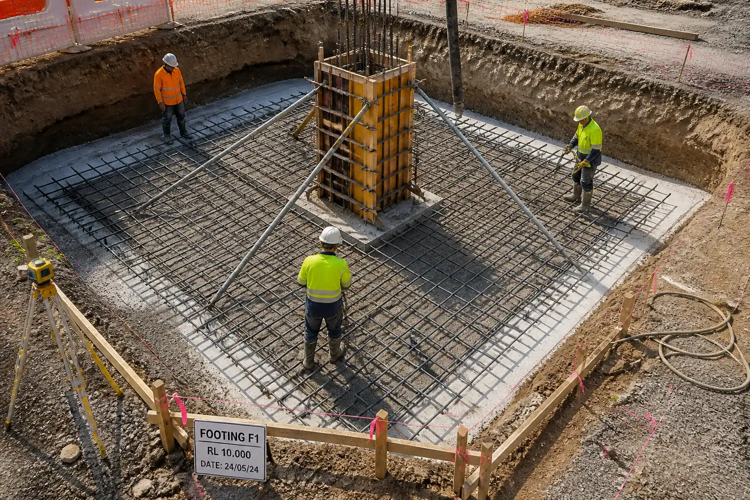
| 1 | Setting out and survey control | Establish control points; set out pile cap and tie-beam centerlines/edges; mark cap formation level and pile cut-off elevation. | Land Surveyor / Site Engineer | Internal check; RFI to Engineer for verification if required |
| 2 | Local excavation and dewatering (if required) | Excavate to expose pile heads and blinding level; maintain safe slopes/shoring; control groundwater via sump/pumps. | Site Engineer / Foreman | HSE inspection; benching/shoring check |
| 3 | Pile head chipping/breaking to cut-off | Mark design cut-off; use hydraulic breaker to within ~100 mm of rebar; final trimming by small chipping hammers/hand tools; avoid rebar damage; remove weak concrete/laitance; clean with air/water. | Site Engineer / Specialist (if required) | Hold/Witness by Engineer |
| 4 | Pile reinforcement preparation | Straighten and clean projecting bars; if dowels required, drill holes to specified diameter/depth; fix bars with approved grout/epoxy; respect development/splice lengths. | Site Engineer / Rebar Foreman | Engineer witness for dowel embedment |
| 5 | Subgrade preparation and blinding | Compact formation if disturbed; place polyethylene sheet if specified; pour blinding 50–75 mm; finish level and cure lightly. | Site Engineer | Engineer inspection prior to rebar |
| 6 | Fix reinforcement for pile cap | Erect bottom mats on chairs/spacers; tie bars as per BBS; install shear links; maintain cover (bottom/sides 75 mm; top 50 mm) [Verify]. Install column starters/anchor bolts if applicable. | Rebar Foreman / Site Engineer | Hold point – reinforcement inspection |
| 7 | Tie-beam starter integration | Place and secure tie-beam starter bars/couplers to required projection and alignment; ensure no clash with cap steel; provide continuity per design. | Rebar Foreman / Site Engineer | Engineer witness |
| 8 | Formwork/shuttering | Apply release agent; fix side shutters with chamfers (20–25 mm); provide kickers if specified; ensure stability, line/level, joints tight to prevent grout loss; provide access and pour openings. | Formwork Foreman / Temporary Works Engineer | Engineer inspection prior to pour |
| 9 | Pre-pour checks and trial tests | Confirm embedments, sleeves, earthing, conduit positions; confirm dewatering; place backup vibrator; conduct slump/temperature on first truck; brief pour team. | QA/QC Engineer / Site Engineer | Engineer witness |
| 10 | Concrete placement and compaction | Place by pump in layers ≤300–400 mm; avoid segregation and rebar displacement; vibrate systematically with overlap; control pour rate to avoid cold joints. | Concrete Foreman / Pump Operator | Continuous QC monitoring |
| 11 | Surface finishing and curing | Strike off and float top; apply curing compound or wet hessian + polythene; protect from traffic, rain, thermal shock; maintain curing ≥7 days or as specified. | Concrete Foreman / QA/QC | QC inspection |
| 12 | Formwork striking | Remove side forms when concrete reaches safe strength; protect arises; repair minor defects with approved mortar. | Formwork Foreman / QA/QC | Engineer witness if required |
| 13 | Tie-beam construction | If monolithic: included in Step 10. If sequential: prepare construction joint (roughen to 6–10 mm amplitude), clean SSD, apply bonding agent if specified; install beam formwork/soffit support; place/vibrate concrete. | Site Engineer / Rebar & Formwork Foremen | Engineer hold on joint prep and rebar |
| 14 | Backfilling around pile caps | After achieving required strength, place approved backfill in layers with compaction; protect protruding starters. | Site Engineer / Foreman | QC compaction checks (if specified) |
| 15 | As-built survey and handover | Survey top of cap, positions of starters/dowels, tie-beam alignments; compile dossier. | Land Surveyor / QA/QC | Engineer review |
Safety Controls
For each hazard: Hazard → Consequence → Control → PPE → Collective Measure → Inspection/Permit
-
Underground services strike → Electrocution, flooding → Permit to Dig, calibrated locator, trial pits, 0.5 m hand-dig exclusion near marks → Dielectric gloves (if required), safety boots → Service plans on board, physical barriers → Utility clearance, PTD sign-off [Verify per project HSE plan and local regulations].
-
Excavation collapse/fall → Burial, fractures → Benching/shoring per design; safe access ladders every 6–9 m; edge protection 1.1 m high; spoil >1 m from edge → Helmet with chin strap, boots → Edge guardrails, trench boxes → Daily excavation inspection by competent person; Confined Space permit where applicable.
-
Pile head breaking with breakers → Flying debris, HAVS, bar damage → Use small chipping hammers near rebar; exclusion zone 3 m; tool inspection; HAVS time tracking; splash screens → Safety glasses/face shield, vibration gloves, hearing protection → Debris nets/screening → Permit to Work for breaking/noise; supervisor present.
-
Silica dust → Respiratory illness → Wet suppression/vacuum extraction; limit dry cutting → FFP3/N95 respirator → Water suppression kits, dust monitors → HSE inspection and records.
-
Noise and vibration → Hearing loss, community complaint → Schedule noisy works daytime; acoustic blankets → Ear defenders → Perimeter noise barriers → Noise permit/monitoring logs.
-
Lifting operations (rebar mats/formwork) → Crush/struck-by → Appointed Person lift plan, certified crane/slings, taglines, no-go zones, banksman control → Gloves, hard hat with chin strap → Exclusion barriers, radio comms → Lifting permit; pre-lift checklist.
-
Concrete pump/hose handling → Whip, splash burns → Secure couplings, clamp checks, prime safely, spotter control → Eye protection, waterproof gloves, long sleeves → Hose restraints, pump matting → Pump setup inspection; manufacturer’s checklist.
-
Rebar impalement → Puncture trauma → Cap all protruding bars with mushroom caps or timber blocks → Gloves → Collective capping across zones → Daily safety walkdowns.
-
Electrical tools/lighting → Shock, fire → 110 V or RCD-protected circuits, IP-rated site lighting, PAT tested → Dielectric gloves (as needed) → Cable routing overhead/gantries → Electrical permit if required; inspection tags.
-
Manual handling of heavy bars → Strains → Team lifts, mechanical aids, bend-keep-close technique → Gloves, back support (if approved) → Use spreader beams/forks → Manual handling training verification.
-
Heat/cold stress during concreting → Heat stroke/hypothermia → ACI 305/306 measures; shaded rest, hydration; warm clothing in cold → Weather-appropriate PPE → Rest shelters, temperature monitoring → HSE weather protocol activation.
-
Work at height on formwork → Fall → Full-edge platforms with guardrails; ladders tied; fall arrest where needed → Harness if collective protection not feasible → Scaffold/MEWP with tags → Work at Height permit; scaffold inspections.
-
Groundwater/dewatering discharge → Slip, contamination → Hose management, drip trays, sediment control → Rubber boots → Bunded pump area → Environmental permit (if required).
Emergency preparedness: First-aid kits; eyewash; rescue plan for excavation; spill kits; emergency contacts display; muster points established.
Environmental Controls
- Dust control: Wet suppression during breaking; avoid dry cutting; wheel-wash for haul roads; visual dust monitoring; stop work thresholds [Verify per project].
- Noise/vibration: Daytime work hours; acoustic screens; equipment maintenance; community notice for peak activities; compliance with site noise limits [Verify].
- Concrete washout: Designated lined washout pit; no discharge to soil/drains; collect and dispose via licensed contractor; pH-neutralization if required.
- Dewatering effluent: Use settlement tank/bag; silt fence around discharge; sample turbidity if mandated [Verify]; no sheen from hydrocarbons.
- Spoil and waste: Segregate concrete waste, rebar offcuts, timber/ply; remove to approved facilities; maintain waste transfer notes.
- Form oil/chemicals: Store in bunded areas; drip trays during application; avoid contact with reinforcement or soil; SDS available.
- Material efficiency: Optimize bar cutting per BBS; reuse formwork; protect materials from weather to reduce waste.
- Flora/fauna and water bodies: Maintain buffer distances; spill response plan; no fueling within 20 m of drains [Verify].
- Incident reporting: Record and investigate environmental nonconformities; corrective actions logged.
QA/QC
- Hold/Witness points: Pile head trimming (Hold), Reinforcement inspection (Hold), Formwork (Hold), Pre-pour (Witness), Construction joint prep for tie-beams (Hold), Final as-built (Witness). Record via WIR.
- Dimensional tolerances: Per ACI 117/EN 13670. Typical [Verify]:
- Pile cap plan position: ±25 mm; top level: ±10 mm; thickness: −10/+15 mm.
- Pile location vs design: within 75 mm typical [Verify].
- Cover: bottom/sides 75 mm; top 50 mm; tolerance −0/+10 mm [Verify].
- Reinforcement: Grade and size as per BS 4449/ASTM A615; laps/development per ACI 318/EN 1992; cleanliness verified; no welding unless approved and per BS EN ISO 17660.
- Concrete: Class and exposure per design; slump 100–160 mm for pumped [Verify]; temperature at discharge 5–32°C [Verify]; max free fall 1.5 m; consolidation by internal vibrators (spacing approx. 10× head diameter; penetration into previous layer ≥50 mm).
- Sampling/Testing: Minimum 1 set (≥6 cubes or 4 cylinders) per 50 m³ per pour/day, whichever is greater [Verify per project]. Slump and temperature each truck [Verify]. Strength acceptance per BS EN 206/ASTM C39 and project criteria.
- Curing: Maintain moisture ≥7 days or until 70% fck achieved [Verify]; hot/cold measures per ACI 305/306.
- Construction joints: If not monolithic, prepare joint surface: expose coarse aggregate (6–10 mm amplitude), clean, SSD; bonding agent only if specified.
- Defect remediation: Honeycombs or voids to be assessed; minor defects repaired using polymer-modified mortar after Engineer approval; major defects require NCR and repair procedure.
- Records: Pre-pour checklist, MIR/MTCs, delivery tickets, test results, calibration certificates, WIRs, inspection checklists, as-built survey, curing logs, HSE permits, NCR/CAR if any.
Attachments
- Approved construction drawings (pile caps, tie-beams, details, sections)
- Approved BBS and rebar shop drawings
- Concrete mix design approvals and trial mix results
- Manufacturer data sheets: grout/epoxy, curing compound, release agent; MSDS
- Temporary works design and formwork calculations/approvals
- Lifting plan and certificates (crane, slings, shackles), operator licenses
- Equipment calibration certificates (survey, testing)
- Permits: Permit to Dig, Permit to Lift, Confined Space (if applicable), Noise/Vibration permits
- Pre-pour checklists, WIR templates, QA/QC forms
- HSE risk assessment, toolbox talk records, emergency response plan
- As-built survey templates and sample records
This content is a read-only public reference. Download or customize to get an editable version.
ITP preview
The first inspection activities from the linked ITP for Method Statement – Reinforced Concrete Pile Cap Construction and Tie-Beam Integration:
| Activity | Inspection / Test | Acceptance Criteria | Responsibility | Record |
|---|---|---|---|---|
| Setting out verification | Survey check of coordinates and levels | Within specified tolerances [Verify] | Contractor QA/QC, Engineer | Survey report, RFI approval |
| Excavation and formation preparation | Visual check, level measurement | Dry, firm base; level ±10 mm | Contractor, Engineer (witness) | Inspection checklist, photos |
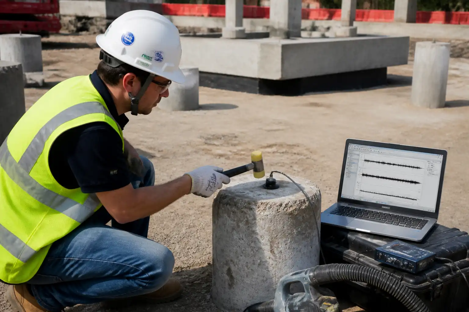
| Pile head trimming to cut-off | Visual and hammer test; rebar integrity check | At or up to +25 mm above design; no rebar damage; sound concrete exposed | Contractor, Engineer (hold) | WIR approval, photos |
Showing 3 of 15 inspection activities. View full ITP →
Related Inspection and Test Plan
An Inspection and Test Plan (ITP) is available for Method Statement – Reinforced Concrete Pile Cap Construction and Tie-Beam Integration. The ITP defines the inspection activities, acceptance criteria, hold and witness points, responsible parties, and records required to verify the work described in this method statement.
View the Method Statement – Reinforced Concrete Pile Cap Construction and Tie-Beam Integration ITP →Frequently asked questions
Continue with related Quollnet resources connected to this method statement.