Method Statement: Installation of Unitized Curtain Wall Panels (Tower Crane/Hoist) – Method Statement
AI-assisted method statement with matching ITP, PDF download, and Excel export.
More than a static template
Unlike a downloadable Word or PDF template, this method statement is an AI-assisted editable starting point connected directly to a matching Inspection and Test Plan. Every section is structured, project-adaptable, and ready to export.
- AI-assisted drafting — Customize every section with AI for your specific project scope.
- Linked ITP — A matching inspection and test plan is generated alongside the method statement.
- Multiple export formats — Download as a formatted PDF or editable Excel spreadsheet.
- Editable starting point, not a final document — Review, verify, and adjust all content against your project requirements before use.
Static template vs. Quollnet workflow
| Feature | Static template | Quollnet |
|---|---|---|
| Project-specific content | Manual fill-in required | AI-assisted customization |
| Linked ITP | Separate document, no link | Matching ITP included |
| Export formats | Usually PDF only | PDF and Excel |
| Structured sections | Free-form layout | 13 standardized sections |
| Saved to your account | Local file only | Cloud-saved, reusable |
| Content accuracy | You verify everything | AI-assisted, you still verify |
| Cost | Often free but time-intensive | Free to customize and download |
What you can customize
When you save this method statement to your account, every section becomes editable. The following 13 sections are included:
- Scope — Defines the activity and its boundaries.
- References — Standards, specifications, and drawings.
- Responsibilities — Roles and accountabilities.
- Resources — Labour, plant, and equipment summary.
- Materials — Materials and compliance requirements.
- Equipment — Tools and equipment details.
- Prerequisites — Hold points and pre-conditions.
- Method sequence — Step-by-step construction sequence.
- Safety controls — HSE risk controls and PPE.
- Environmental controls — Environmental mitigation measures.
- QA/QC — Quality inspection and test requirements.
- ITP — Inspection and Test Plan table (has its own page).
- Attachments — Referenced drawings and documentation.
Why this method statement is used
This method statement is used to define and communicate the approved procedure for carrying out method statement: installation of unitized curtain wall panels (tower crane/hoist) on site. It ensures the work is planned in advance, the correct resources and controls are in place, and all personnel understand responsibilities, sequence, quality requirements, and safety controls before work begins. It aligns site execution with the documented scope and acceptance expectations.
Who uses this method statement
This method statement is used by contractors, site supervisors, project engineers, QA/QC engineers, HSE officers, consultants, and client representatives. It serves as a shared reference for planning, execution, supervision, inspection, and approval of the activity on site.
When it is prepared and submitted
The method statement is prepared before the work activity starts and submitted as part of the pre-construction documentation package for review and approval.
Who reviews or approves it
The method statement is usually submitted to the client representative, consultant, resident engineer, or project management consultant for review and approval before the work commences.
Important approval note
This method statement is an AI-assisted editable starting point, not a pre-approved document. Before use on any project, all content must be reviewed and approved by the relevant parties (superintendent, principal contractor, or client representative) in accordance with your contract and project quality plan.
For example: if your specification requires a departure from a referenced standard, that departure must be documented and approved separately — this method statement will not capture that automatically. Always verify against your applicable drawings, specifications, and regulatory requirements.
Method statement content
Scope
Work Summary
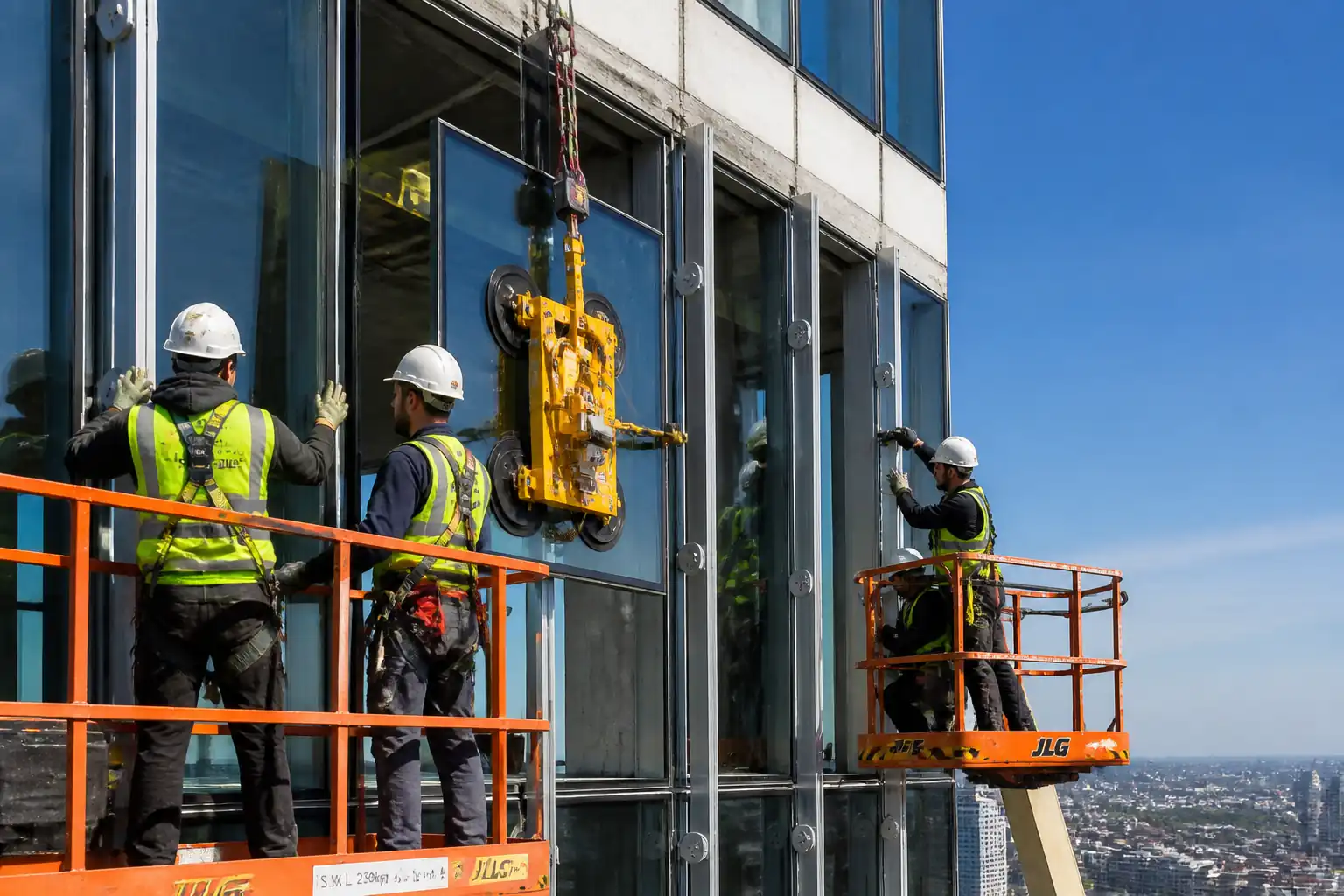
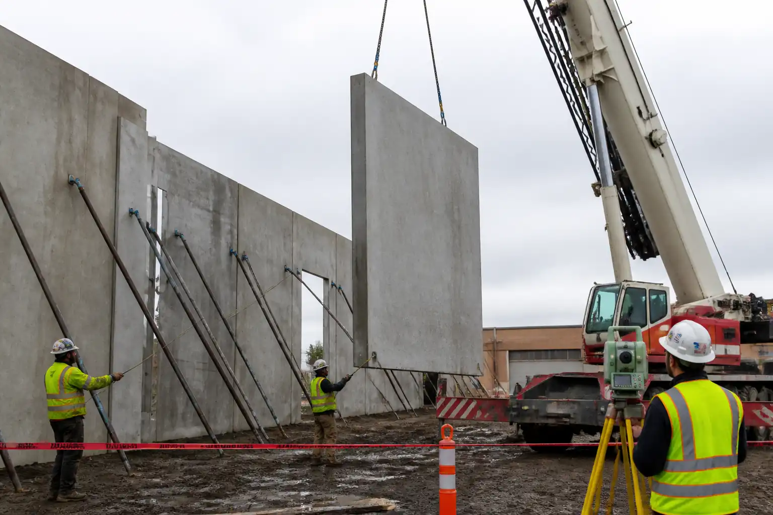
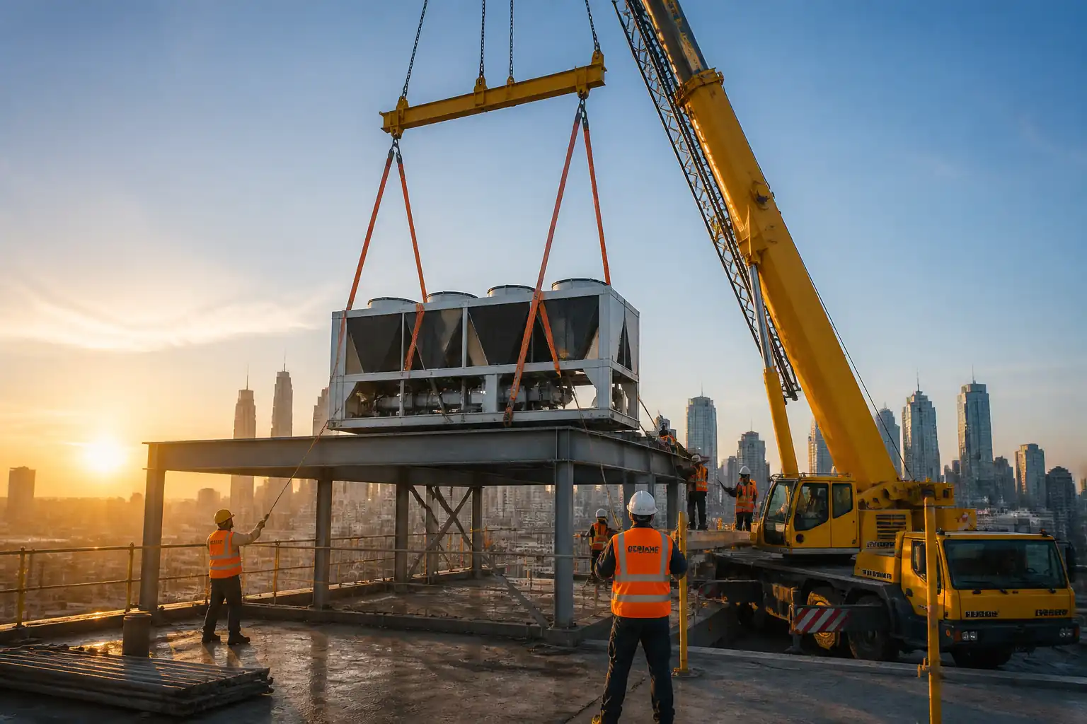
This method statement covers the end-to-end installation of unitized curtain wall panels on using a tower crane or material hoist. It includes survey setting-out, bracket and rail alignment, safe lifting and handling of unitized panels, interlocking and engagement of stack/mullion joints, gasket compression checks, weather-seal continuity, movement joint treatment at slab edges and inter-panel joints, QA/QC dimensional verification, and formal hold points at each floor level prior to progressing upwards.
Included Activities
- Pre-installation verification: design/shop drawing approvals, mock-up approval, delivery inspection, lifting/rigging plan, permits, and toolbox talks.
- Survey control: transfer of primary control to façade grid, bracket and rail alignment tolerances.
- Anchor/bracket/rail installation (where applicable to the system), shimming, torqueing, and verification.
- Lifting, landing, and installation of unitized panels from tower crane or hoist with dedicated spreader/vacuum lifter and taglines.
- Interlocking of male/female profiles, stack joint engagement, gasket compression verification, and temporary restraints removal.
- Weather seal continuity works, sealant application, and backer rod installation as required by the system supplier.
- Movement joints: slab edge/head-of-wall allowances, thermal and seismic movement provisions, and compatible fire/smoke barriers where specified [Verify per project specifications].
- QA/QC inspections, records, and field performance testing per ITP.
- Housekeeping, protection, and turnover documentation.
Exclusions
- Structural modification of primary structure.
- Permanent power supply, lightning protection.
- Commissioning of BMU systems.
- Repair of pre-existing substrate defects beyond minor grinding/shimming.
References
| Document Type | Reference / Number | Revision | Notes |
|---|---|---|---|
| Standard | CWCT (Centre for Window & Cladding Technology) | Apply project-appropriate guidance [Verify per project specifications]. | |
| BS EN | EN 13830 | ||
| BS EN | EN 12152/12154/12155 | ||
| ASTM | ASTM E283, E331, E330 | Where ASTM framework is adopted [Verify per project specifications]. | |
| ASTM/AAMA | ASTM E783, E1105; AAMA 501.2 | Field testing regime per ITP [Verify per project specifications]. | |
| ISO/ASTM | ISO 11600; ASTM C920 | ||
| BS EN | EN 13155; EN 12100 | Plus local lifting regulations [Verify per project HSE plan and local regulations]. | |
| Eurocode | EN 1991-1-4 | For lift wind limits see method; project-specific design governs. | |
| BS EN | EN 10204 | ||
| ISO | ISO 9001/14001/45001 | Apply via project IMS [Verify per project HSE plan and local regulations]. |
Responsibilities
| Role | Responsibility | Name / Party |
|---|---|---|
| Management | Project Manager | Main Contractor |
| Engineering | Façade Manager | Main Contractor |
| Lifting | Appointed Person | Main Contractor |
| Operations | Operator | Approved Subcontractor |
| Lifting | Rigger | Approved Subcontractor |
| Trades | Foreman | Façade Subcontractor |
| Survey | Surveyor | Main Contractor |
| Quality | QA/QC | Main Contractor |
| HSE | HSE | Main Contractor |
| Independent | Tester | Independent |
Resources
| Resource Type | Description | Quantity | Remarks |
|---|---|---|---|
| Manpower | Skilled unitized system installers | 6-10 | |
| Manpower | Certified riggers and signallers | 2-4 | |
| Manpower | Licensed operators with current medical and competency | 1-2 | |
| Manpower | Total station/laser scanning as required | 1 |
Materials
| Material | Specification / Grade | Quantity | Remarks |
|---|---|---|---|
| Aluminium/glass unitized panels | Per approved shop drawings & samples | ||
| Brackets, rails, cleats | Per structural calculations | ||
| Stainless M12–M16, HDPE shims | Manufacturer data [Verify] | ||
| Silicone, primers, cleaners | Manufacturer TDS/SDS | ||
| Mineral wool/foil facings | As per design |
Equipment
| Equipment | Capacity / Type | Quantity | Inspection Required |
|---|---|---|---|
| Tower crane/hoist | Per lift plan [Verify] | 1 | Yes |
| Spreader/lifting frame | >1.5x max panel wt [Verify] | 1 | Yes |
| Vacuum lifter/slings | >2x panel wt [Verify] | 1 | Yes |
| MEWP/scaffold | As required | Yes | |
| Total station/laser | 1 set | Yes | |
| Torque wrench | Up to 300 Nm [Verify] | 2 | Yes |
| Gauges/jigs | Set | No |
Prerequisites
Approvals and Documentation
- Approved shop drawings, system calculations, interface details, sealant compatibility letters, and mock-up test approvals (air/water/structural) [Verify per project specifications].
- Approved lifting plan signed by Appointed Person; permits to lift and work at height issued [Verify per project HSE plan and local regulations].
- ITP and checklists issued. Calibration certificates for survey and torque tools in date.
Site Readiness
- Slab edges surveyed; embeds/anchors released; structural openings within tolerance; fire/smoke barrier areas ready.
- Edge protection in place; access routes clear; crane/hoist commissioned and certified.
- Weather within limits: sustained wind ≤ 10 m/s (22 mph) and gusts ≤ 13 m/s (29 mph) for panel lifts unless manufacturer specifies stricter limits [Verify per lift plan].
Materials and Storage
- Panels delivered with protective packing, stored vertical on A‑frames with spacers; shaded/ventilated; identification labels visible.
- Sealants, primers, gaskets, and shims verified against submittals; shelf life and storage per manufacturer.
Briefings
- Task-specific TBT conducted daily, covering pinch/crush hazards, glass handling, wind limits, exclusion zones, communication signals, and emergency rescue plan.
- Coordination meeting with structure, MEP, and BMU trades to confirm interfaces and daily work faces.
Method Sequence
| Step | Activity | Description | Responsibility | Inspection / Hold Point |
|---|---|---|---|---|
| 1 | Establish Survey Control & Set-Out | Transfer primary control to façade grid using total station. Mark vertical control at corners and every 6–9 m. Establish datum panel line and elevation at first installed floor. | Surveyor | Yes |
| 2 | Bracket/Rail Installation & Shimming | Fix brackets/rails to embeds/anchors as per drawings. Shim to achieve line/level. Do not exceed max shim stack height [Verify per design]. | Façade Installers | Yes |
| 3 | Pre-Lift Panel Inspection | At laydown, verify panel ID, orientation, glazing condition, gaskets, interlocks, and lifting points. Fit temporary protection as needed. | QA/QC + Rigger | Yes |
| 4 | Rigging & Test Lift | Attach lifting frame/vacuum lifter as per manufacturer; confirm COG; perform 200–300 mm test lift to verify balance and suction. | Appointed Person + Riggers | Yes |
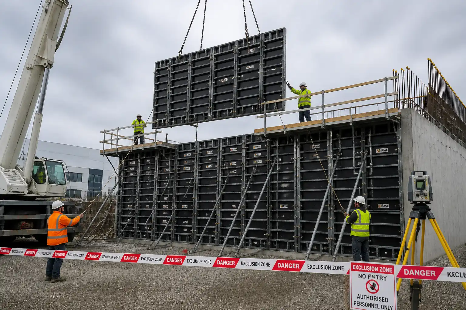
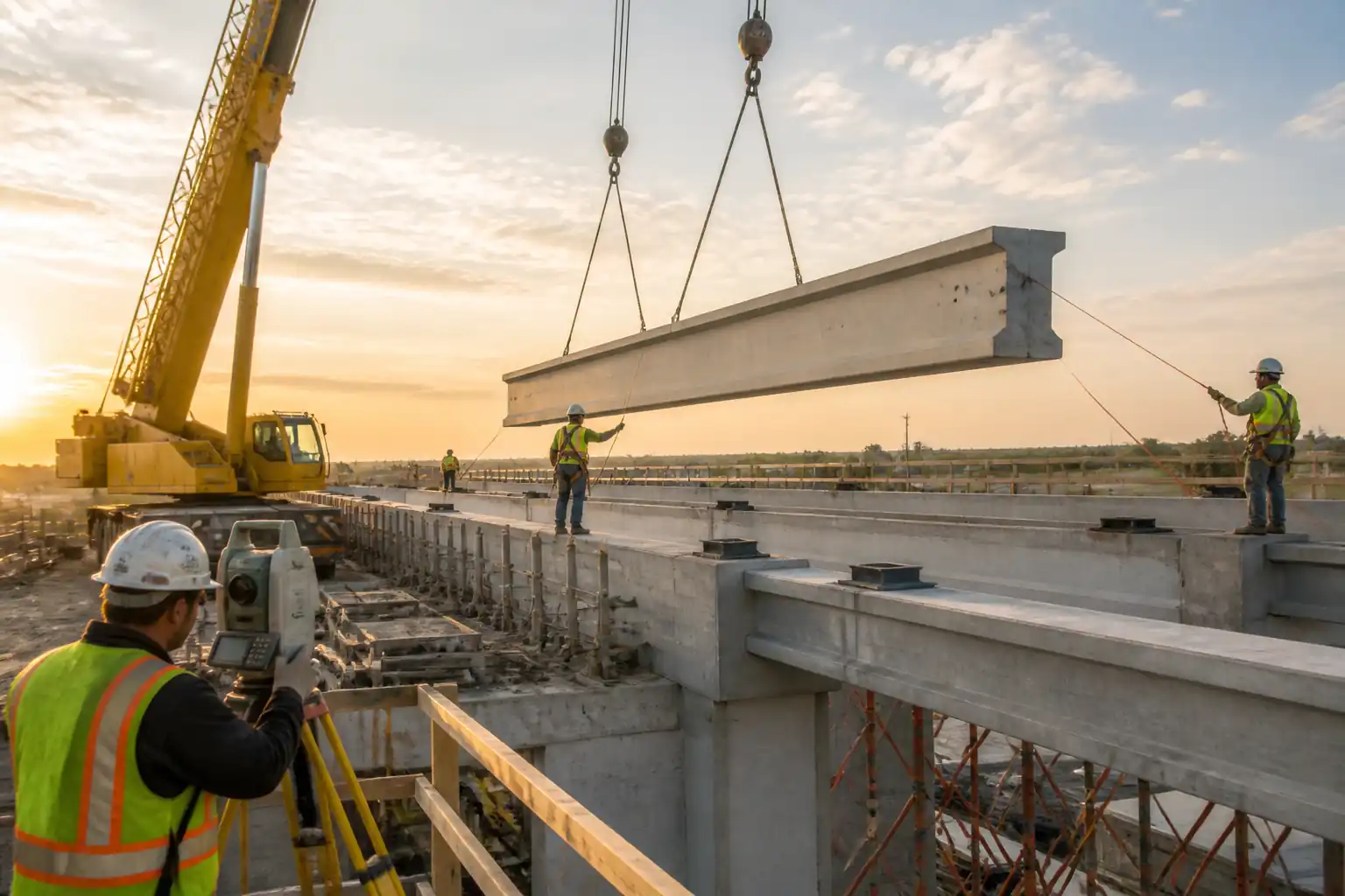
| 5 | Lift & Land to Elevation | Crane/hoist lifts under AP control. Maintain exclusion zone. Use two taglines. Stop lift if wind exceeds limit or load unstable. | Crane Operator + Riggers | Yes |
| 6 | Positioning & Temporary Restraint | Offer panel to brackets/receivers. Engage locating pins. Apply temporary restraints/clamps as per system method. | Façade Installers | Yes |
| 7 | Fixing & Torqueing | Install primary fixings/cleats. Tighten to specified torque using calibrated wrench. Mark bolts after torque (paint witness). | Façade Installers | Yes |
| 8 | Interlocking & Gasket Compression Check | Engage male/female profiles and stack joint. Confirm gasket compression with go/no-go gauge or joint-width verification per system data. | Façade Installers + QA/QC | Yes |
| 9 | Weather Seal Continuity | Clean substrates (two-rag method), prime if required, install backer rod and gun sealant. Tool to achieve required bead geometry. | Sealant Applicator | Yes |
| 10 | Movement Joint Treatment | Verify clearances at slab edge/head and perimeter fire barrier installation where specified. Install covers/flashings per detail. | Façade Installers + Firestop Specialist | Yes |
| 11 | Dimensional & Visual QA/QC | Check plumb, level, plane, joint alignment, glass quality, drainage/weep paths, and labels removal as required. | QA/QC | Yes |
| 12 | Field Testing (Sampling) | Conduct AAMA 501.2 hose test or ASTM E1105/E783 on designated bays after sealant cure. | Third-Party Tester + QA/QC | Yes |
| 13 | Floor-Level Hold Point & Release | Submit floor package for inspection with records (torque logs, survey, sealant batches). Obtain client/consultant sign-off before next level. | QA/QC + Client Rep | Yes |
| 14 | Protection & Housekeeping | Install protective films/edge guards if required. Remove waste/packaging. Secure any temporary works. | Façade Installers | Yes |
Safety Controls
Task-Specific Hazards and Controls
- Hazard: Falling from height at slab edge
- Likely consequence: Major injury or fatality
- Engineering/procedural control: Install edge protection (guardrails/toe boards) and use MEWPs/scaffolds with certified anchorage. 100% tie-off with EN 361 full-body harness and double lanyard when working within 2 m of edge.
- Required PPE: Helmet with chin strap, full-body harness, lanyards with shock absorber, safety boots, cut-resistant gloves, eye protection.
- Collective preventive measure: Perimeter edge protection, netting where practical.
-
Inspection/permit/supervision: Daily scaffold/MEWP inspections; Work at Height PTW; supervision by Site Engineer [Verify per project HSE plan and local regulations].
-
Hazard: Crane/hoist lifting and suspended loads
- Likely consequence: Crush injuries, struck-by, fatality
- Engineering/procedural control: Appointed Person lift plan; certified crane/hoist; exclusion zones barricaded; taglines; standard hand signals/radios; stop work above wind limits; no lifting over personnel; only certified rigging attachments.
- Required PPE: Helmet with chin strap, gloves, high-vis, safety boots, radios for signalman.
- Collective preventive measure: Physical exclusion barriers and banksman control.
-
Inspection/permit/supervision: PTW to lift; pre-use checks; certificates in date; lifting supervision throughout.
-
Hazard: Glass breakage and falling fragments
- Likely consequence: Lacerations, falling debris injuries
- Engineering/procedural control: Use dual-circuit vacuum lifter or padded slings; avoid impact; maintain soft landing; protect leading edges; do not drill/cut on site unless approved; exclusion zone below.
- Required PPE: Cut-resistant gloves/sleeves (ANSI A5–A6), safety spectacles/face shield, long sleeves.
- Collective preventive measure: Debris netting below workface.
-
Inspection/permit/supervision: Inspect glass at delivery; replace damaged panels; HSE oversight.
-
Hazard: Pinch/crush during interlocking and temporary restraint
- Likely consequence: Finger/hand injuries
- Engineering/procedural control: Use panel handles; predefined hand positions; use pry bars and alignment tools instead of fingers in joints; communicate before engaging interlocks.
- Required PPE: Cut-resistant gloves, knuckle protection.
- Collective preventive measure: Task sequencing to avoid simultaneous conflicting actions.
-
Inspection/permit/supervision: Foreman supervision; TBT briefing sign-off.
-
Hazard: Uncontrolled movement due to wind gusts
- Likely consequence: Load swing, loss of control, collision
- Engineering/procedural control: Monitor real-time wind; postpone lifts above limits; use two taglines; position crane to minimize sail effect; avoid lifting near building corners during gusts.
- Required PPE: Standard site PPE; radios for team.
- Collective preventive measure: Weather monitoring station at roof and workface.
-
Inspection/permit/supervision: AP to authorize lift based on conditions; stop-work authority to all.
-
Hazard: Sealant/primer chemical exposure
- Likely consequence: Dermatitis, respiratory irritation, eye injury
- Engineering/procedural control: Review SDS; use compatible cleaners; ensure ventilation; avoid ignition sources with solvent-based primers; closed cartridges where possible.
- Required PPE: Chemical-resistant nitrile gloves, safety glasses, long sleeves; RPE if required by SDS.
- Collective preventive measure: Local ventilation; controlled storage.
-
Inspection/permit/supervision: COSHH/chemical handling assessment; SDS available; HSE inspections.
-
Hazard: Manual handling of heavy components
- Likely consequence: Strains/sprains
- Engineering/procedural control: Team lifts; use dollies/A-frames; keep loads close to body; rotate tasks.
- Required PPE: Safety boots, gloves with grip.
- Collective preventive measure: Mechanical aids preference over manual handling.
-
Inspection/permit/supervision: Manual handling training records verified.
-
Hazard: Interface with post-tensioned slabs/embedded services
- Likely consequence: Structural damage, cable strike
- Engineering/procedural control: Confirm as-built PT/embedded services locations; do not drill outside approved zones; use manufacturer-approved anchors only.
- Required PPE: Standard PPE.
- Collective preventive measure: Permit to drill (if any); marked no-drill zones.
- Inspection/permit/supervision: Engineer sign-off on bracket fixings; records kept.
Environmental Controls
Environmental Risks and Controls
- Packaging and offcuts waste
-
Control: Segregate aluminum, glass, timber, and plastic for recycling; provide labeled skips; record weights.
-
Sealant VOCs and solvent use
-
Control: Select low-VOC products where possible; store sealed; apply in well-ventilated areas; prevent spills; keep spill kits available.
-
Noise from crane operations/MEWPs and impact tools
-
Control: Work within permitted hours; use low-noise tools where feasible; maintain equipment.
-
Water discharge from field testing
-
Control: Capture and direct water to drains via sediment socks; prevent run-off over public areas; obtain permit for discharge if required [Verify per local regulations].
-
Dust/debris from drilling/grinding (if any local correction)
-
Control: Local extraction; wet methods; immediate cleanup; prevent material from falling off edges with debris netting.
-
Energy and idling
-
Control: Shut off engines when idle; schedule lifts to reduce waiting; maintain equipment for efficiency.
-
Protection of installed façade
- Control: Use protective films/edge guards; prohibit abrasive cleaners; prevent contact with cementitious runoff.
QA/QC Requirements
Quality Controls
- Material traceability: Maintain EN 10204 3.1 certificates for metallic components; retain sealant batch numbers and expiry.
- Calibration: Total station, laser tools, torque wrenches with valid calibration certificates.
- Tolerances: Use CWCT-typical tolerances unless project specifies otherwise: plumb/level within ±3 mm per 3 m and ±5 mm overall; joint alignment ±2 mm; panel step ≤ 2 mm; bracket position ±2 mm [Verify per project specifications].
- Fastening: Apply manufacturer torque; record bolt ID, location, and achieved torque; witness mark.
- Gasket compression: Verify continuous engagement; target 30–50% compression unless otherwise specified; use go/no-go gauge or documented method [Verify].
- Sealant works: Substrate cleaning method, primer use, bead dimensions, tooling quality, cure verification before testing; maintain environmental conditions within TDS ranges (temperature/substrate moisture) [Verify].
- Movement joints: Verify design allowances and fire/smoke barrier integrity; photo records prior to close-up.
- Field testing: Perform per ITP sampling plan (e.g., AAMA 501.2 early; ASTM E1105/E783 at agreed frequency) with acceptance per project criteria [Verify].
- Documentation: ITP checklists, survey as-builts, torque logs, sealant batch logs, NCRs/Corrective actions, floor-level hold point certificates.
Hold Points
- HP-1: Bracket/Rail alignment acceptance prior to panel installation on each new bay/elevation.
- HP-2: Rigging arrangement approval before first lift and any change of panel type/weight.
- HP-3: Interlock and gasket compression verification on first two panels per elevation.
- HP-4: Movement joint/fire barrier close-up inspection before proceeding along the run.
- HP-5: Floor-level completion acceptance before starting the level above.
Attachments
- Approved shop drawings and elevations
- Lift plan and rigging drawings with SWLs and wind limits
- Panel numbering and installation sequence map
- Sealant manufacturer TDS/SDS and compatibility letters
- Torque wrench calibration certificates
- Survey control and as-built reports
- ITP forms and checklists (blank and completed samples)
- Risk assessment and method statement (RAMS) sign-off sheets
- Mock-up and laboratory test reports (air/water/structural)
- Emergency rescue plan for work at height
This content is a read-only public reference. Download or customize to get an editable version.
ITP preview
The first inspection activities from the linked ITP for Method Statement: Installation of Unitized Curtain Wall Panels (Tower Crane/Hoist):
| Activity | Inspection / Test | Acceptance Criteria | Responsibility | Record |
|---|---|---|---|---|
| Survey control transfer and façade set-out | Check lines/levels with total station | Plumb/level within specified tolerances [Verify]. | Surveyor / QA/QC | Survey report |
| Bracket/Rail installation and torqueing (HP-1) | Dimensional check; torque verification | Positions ±2 mm; torque per manufacturer [Verify]. | Façade Manager / QA/QC | Bracket checklist; torque log |
| Rigging equipment readiness (HP-2) | Certs, tags, vacuum leak-down | Certification valid; leak rates within OEM limits. | Appointed Person / QA/QC | Rigging inspection record |
Showing 3 of 11 inspection activities. View full ITP →
Related Inspection and Test Plan
An Inspection and Test Plan (ITP) is available for Method Statement: Installation of Unitized Curtain Wall Panels (Tower Crane/Hoist). The ITP defines the inspection activities, acceptance criteria, hold and witness points, responsible parties, and records required to verify the work described in this method statement.
View the Method Statement: Installation of Unitized Curtain Wall Panels (Tower Crane/Hoist) ITP →Frequently asked questions
Continue with related Quollnet resources connected to this method statement.