Method Statement: Stick-Built Aluminium Curtain Wall Construction – Method Statement
AI-assisted method statement with matching ITP, PDF download, and Excel export.
More than a static template
Unlike a downloadable Word or PDF template, this method statement is an AI-assisted editable starting point connected directly to a matching Inspection and Test Plan. Every section is structured, project-adaptable, and ready to export.
- AI-assisted drafting — Customize every section with AI for your specific project scope.
- Linked ITP — A matching inspection and test plan is generated alongside the method statement.
- Multiple export formats — Download as a formatted PDF or editable Excel spreadsheet.
- Editable starting point, not a final document — Review, verify, and adjust all content against your project requirements before use.
Static template vs. Quollnet workflow
| Feature | Static template | Quollnet |
|---|---|---|
| Project-specific content | Manual fill-in required | AI-assisted customization |
| Linked ITP | Separate document, no link | Matching ITP included |
| Export formats | Usually PDF only | PDF and Excel |
| Structured sections | Free-form layout | 13 standardized sections |
| Saved to your account | Local file only | Cloud-saved, reusable |
| Content accuracy | You verify everything | AI-assisted, you still verify |
| Cost | Often free but time-intensive | Free to customize and download |
What you can customize
When you save this method statement to your account, every section becomes editable. The following 13 sections are included:
- Scope — Defines the activity and its boundaries.
- References — Standards, specifications, and drawings.
- Responsibilities — Roles and accountabilities.
- Resources — Labour, plant, and equipment summary.
- Materials — Materials and compliance requirements.
- Equipment — Tools and equipment details.
- Prerequisites — Hold points and pre-conditions.
- Method sequence — Step-by-step construction sequence.
- Safety controls — HSE risk controls and PPE.
- Environmental controls — Environmental mitigation measures.
- QA/QC — Quality inspection and test requirements.
- ITP — Inspection and Test Plan table (has its own page).
- Attachments — Referenced drawings and documentation.
Why this method statement is used
This method statement is used to define and communicate the approved procedure for carrying out method statement: stick-built aluminium curtain wall construction on site. It ensures the work is planned in advance, the correct resources and controls are in place, and all personnel understand responsibilities, sequence, quality requirements, and safety controls before work begins. It aligns site execution with the documented scope and acceptance expectations.
Who uses this method statement
This method statement is used by contractors, site supervisors, project engineers, QA/QC engineers, HSE officers, consultants, and client representatives. It serves as a shared reference for planning, execution, supervision, inspection, and approval of the activity on site.
When it is prepared and submitted
The method statement is prepared before the work activity starts and submitted as part of the pre-construction documentation package for review and approval.
Who reviews or approves it
The method statement is usually submitted to the client representative, consultant, resident engineer, or project management consultant for review and approval before the work commences.
Important approval note
This method statement is an AI-assisted editable starting point, not a pre-approved document. Before use on any project, all content must be reviewed and approved by the relevant parties (superintendent, principal contractor, or client representative) in accordance with your contract and project quality plan.
For example: if your specification requires a departure from a referenced standard, that departure must be documented and approved separately — this method statement will not capture that automatically. Always verify against your applicable drawings, specifications, and regulatory requirements.
Method statement content
Scope
Overview
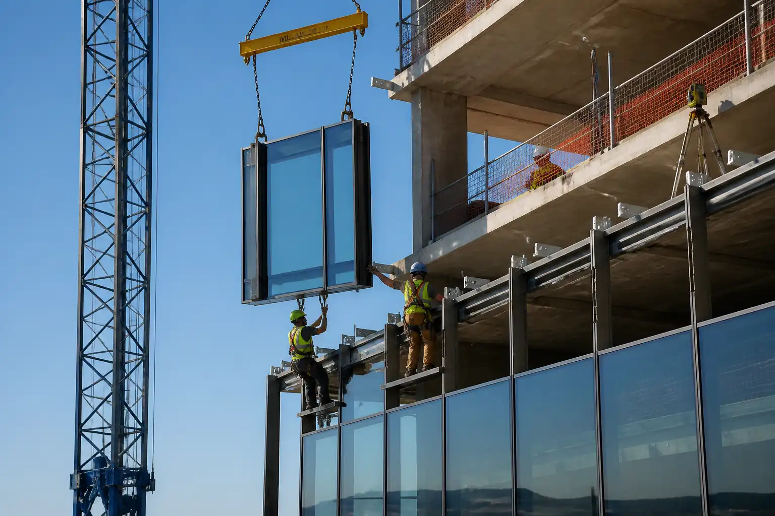
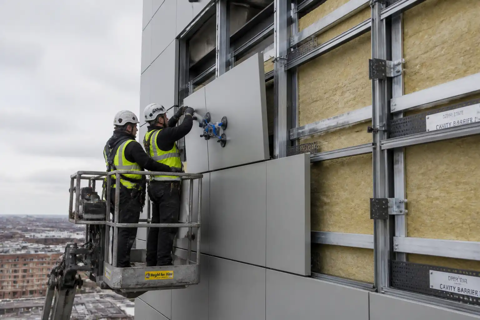
This method statement covers the complete site installation of a stick-built aluminium curtain wall system, including:
- Setting out and survey verification
- Installation of post-installed anchors and primary brackets to structure
- Erection of vertical mullions and horizontal transoms
- Installation of gaskets, setting blocks, and glazing units (IGUs/laminated/tempered)
- Fixing of pressure plates and snap-on cover caps
- Formation of drainage/ventilation paths and weep provisions
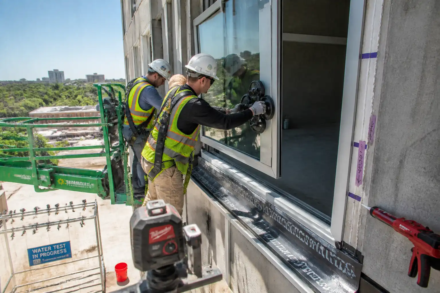
- Application of perimeter and weather sealants; compatibility/adhesion checks
- QA/QC inspections and tests (hold/witness points) for substrate, anchors, plumb/level, torque, glazing, and field water/air tests
- Final cleaning, protection, and handover documentation
Exclusions/Interfaces
- Primary structural frame tolerances beyond receiving faces
- Firestopping/spandrel insulation unless specified otherwise [Verify per project specifications]
- BMU and external access systems (interface coordination only)
- Electrical/lighting within mullions (interface only)
Key Performance Objectives
- Dimensional compliance to design drawings and tolerances
- Weathertightness with functional drainage/ventilation
- Verified anchor capacities and correct torque on pressure plates
- Safe work at height with controlled lifting of glass and profiles
- Defect-free finishes without damage to coatings or glass edges
[All values and system-specific instructions to be verified against approved shop drawings, manufacturer’s manuals, and project specifications.]
References
| Document Type | Reference / Number | Revision | Notes |
|---|---|---|---|
| Standard | BS EN 13830 Curtain walling — Product standard | System performance and definitions for curtain walling. | |
| Standard | EN 1992-4 Design of fastenings for use in concrete | Design basis for mechanical/chemical post-installed anchors to concrete. | |
| Standard | ASTM E283, E330/E330M, E331 | Air leakage, structural performance, and water penetration test methods (laboratory). | |
| Standard | ASTM E783, ASTM E1105, AAMA 501.2 | Field air leakage, field water penetration, and hose spray field check. | |
| Standard | BS EN 12150, EN 14179, EN 1279, EN 14449 | Tempered, heat-soaked tempered, insulating glass units, and laminated glass. | |
| Standard | ASTM C1184, ASTM C920, ASTM C794/C1521 | Silicone for structural glazing, elastomeric sealants, and adhesion/field adhesion tests. | |
| Standard | ISO 3506 (stainless steel fasteners), BS EN 12206 (powder coating), Qualicoat/Qualanod | Fastener grades; coating/anodizing quality requirements. | |
| Standard | ETAG 001/EAD for post-installed anchors (or ICC-ES ESR) | European Technical Assessments for anchors, for product qualification and installation parameters. | |
| Specification | CSI MasterFormat 08 44 13 – Glazed Aluminum Curtain Walls | Typical specification section for submittals, tolerances, finishes, tests. [Verify per project specifications]. |
Responsibilities
| Role | Responsibility | Name / Party |
|---|---|---|
| PM | Project Manager | Main Contractor |
| SE | Site Engineer | Main Contractor |
| Supervisor | Facade Subcontractor Supervisor | Facade Subcontractor |
| QA/QC | QA/QC Engineer | Main Contractor / Subcontractor |
| HSE | HSE Officer | Main Contractor |
| Surveyor | Setting Out Surveyor | Main Contractor / Facade Subcontractor |
| Independent Lab | Third-Party Tester | Approved Laboratory |
Resources
| Resource Type | Description | Quantity | Remarks |
|---|---|---|---|
| Curtain Wall Installation Crew | 1 crew per elevation (1 supervisor, 2 installers, 2 glaziers, 1 rigger) | Adjust to program and access constraints. | |
| MEWP Operators (IPAF) | 2 certified operators | Scissor/boom per reach; current certification required. | |
| Appointed Person / Lift Supervisor | As required by lift plan | For glass lifting/mini-crane operations. |
Materials
| Material | Specification / Grade | Quantity | Remarks |
|---|---|---|---|
| Aluminium Mullions/Transoms/Caps | Supplier/system: |
||
| Post-Installed Anchors | Design per EN 1992-4; manufacturer installation instructions; stainless steel where exposed. [Verify] | ||
| Fasteners (Bracket bolts, pressure plate screws) | ISO 3506; torque per system manual (e.g., M6: 8–12 N·m; M8: 15–20 N·m). [Verify] | ||
| Setting Blocks/Spacers/Glazing Tapes | ASTM C864; thickness/length per glass size and load. [Verify] | ||
| Insulating Glass Units (IGUs) | EN 1279; tempered to EN 12150 and/or heat-soaked EN 14179; laminated to EN 14449 where required. Heat soak where specified. [Verify] | ||
| Gaskets (EPDM) | ASTM C864; profile per system; continuity at corners with vulcanized joints where provided. | ||
| Sealants (Weather/Perimeter) | ASTM C920, Type S/M, Grade NS; adhesion per ASTM C1521 field test; primer as recommended. [Verify] | ||
| Thermal Break/Isolators | System-specific; maintain continuity and avoid bridging. [Verify] |
Equipment
| Equipment | Capacity / Type | Quantity | Inspection Required |
|---|---|---|---|
| Total Station / Laser Level | ±1 mm @ 30 m; with calibrated targets | ||
| MEWPs (Scissor/Boom) | Working height per elevation; current inspection tags | ||
| Mini-crane/Glass Lifter (Vacuum) | Rated for heaviest lite + 25% margin; dual-circuit vacuum with alarms | ||
| Torque Wrenches | Range 2–50 N·m; calibration within 6 months | ||
| Rotary Hammer Drills + Dust Extraction | Bits per anchor size; depth stop; HEPA extraction | ||
| Blow-out Pump/Air + Hole Brushes | Per anchor ETA installation sequence | ||
| Hand Tools & PPE | Glass handling tools, rubber mallets, sealant guns (ratio per sealant), edge protection |
Prerequisites
- Approved shop drawings, structural calculations, setting-out drawings, and coordination with adjacent trades.
- Method Statement and ITP approved by Engineer/Client.
- Access plan and lift plan approved; MEWP and lifting equipment inspected and certified.
- Weather limits established: no glazing or lifting if sustained wind ≥10 m/s (22 mph) or gusts ≥13 m/s; avoid sealant works below 5°C or above 40°C or on wet/frosted substrates [Verify per manufacturer].
- Substrate acceptance: structure within tolerance; concrete/steel strength verified; no loose material; survey as-built completed and benchmarks transferred.
- Utilities/embedded PT cables scanned before drilling (GPR/ferroscan) and marked on drawings.
- Material deliveries inspected; coating protection in place; glass edge labels intact; storage dry and on padded racks.
- Mock-up or first-of-kind bay completed and approved where specified.
- Sealant compatibility letters and primer schedules from manufacturers; test panels arranged for adhesion checks.
- HSE documentation: task-specific risk assessments, permits to work (work at height, lifting, hot works if any), rescue plan for MEWP. [Verify per project HSE plan and local regulations].
Method Sequence
| Step | Activity | Description | Responsibility | Inspection / Hold Point |
|---|---|---|---|---|
| 1 | Setting Out & Verification | Establish control points/lines using total station; transfer datums to each floor; verify structural openings vs. shop drawings; mark bracket locations with unique IDs. | Site Engineer/Surveyor | Hold: Substrate/lines acceptance |
| 2 | Anchor Hole Drilling & Preparation | Scan for rebar/PT and approve locations; drill per ETA diameter/depth with depth-stop; maintain edge/spacings; clean holes by brush–blow–brush–blow sequence or per manufacturer; maintain dry/clean holes for bonded anchors. | Anchor Crew (Certified) | Witness: Hole dimensions/cleanliness |
| 3 | Anchor Installation (Mechanical or Bonded) | Install anchors to specified embedment; for bonded anchors, inject adhesive from hole bottom with proper nozzle; respect gel/cure times; for mechanical, tighten to setting torque using calibrated wrench. | Anchor Crew | Hold: First-article installation |
| 4 | Bracket Installation & Shimming | Fix primary brackets to anchors; use isolators and corrosion barriers; shim/pack to achieve line/level allowing designed tolerance. Tighten bracket bolts to specified torque; lock washers or thread-locker as required. | Facade Installer | Witness: Alignment |
| 5 | Mullion Erection | Lift mullions to position using MEWP and certified glass/vacuum lifter or slings with edge protection; seat on brackets/cleats; install isolation pads; temporarily brace; check plumb; fix per sequence starting from base upward. | Facade Installer | Hold: First bay plumb/line |
| 6 | Transom Installation | Install transoms between mullions; ensure correct drainage orientation; fix with concealed screws/clips; verify level; install thermal breaks/isolators. | Facade Installer | Witness |
| 7 | Gasket/Accessory Installation | Install internal gaskets continuously; vulcanize or bond corners as per system; fit setting blocks at quarter points; install spacers and baffles; ensure no blockage of drainage paths. | Facade Installer | Witness |
| 8 | Glazing Unit Insertion | Clean rebates; lift IGUs with vacuum lifter; insert onto setting blocks; verify edge clearances and bite; install side spacers; avoid glass-to-metal contact; protect edges; do not glaze in winds ≥10 m/s or rain. | Glazing Crew | Hold: First lite per elevation |
| 9 | Pressure Plate Installation & Torqueing | Install pressure plates with specified gasket; start from center working outwards; apply screws at designed spacing; torque in two passes with calibrated wrench; verify uniform compression and thermal break continuity. | Facade Installer | Witness: Torque audit |
| 10 | Cover Cap Installation | Snap-on or mechanically fix cover caps; ensure alignment and consistent joint gaps; install joint splices as required; protect finishes. | Facade Installer | Visual |
| 11 | Perimeter/Weather Sealant Application | Clean and prime substrates; insert backer rod; gun sealant continuously; tool for concave profile; maintain joint width/depth ratio per manufacturer (typ. width 10–20 mm; depth 1/2 width) [Verify]. | Sealant Applicator (Approved) | Witness: Adhesion tests |
| 12 | Drainage/Weep Provisions | Form/verify weep holes/slots at transoms and mullion bases; install baffles/bug screens; check continuity of pressure-equalization paths. | Facade Installer | Witness |
| 13 | Field Performance Testing | Conduct field air leakage (ASTM E783) and water penetration (ASTM E1105) on agreed bays; conduct hose test AAMA 501.2 where specified; remedy and retest if required. | Third-Party Tester with Subcontractor | Hold: Testing |
| 14 | Cleaning, Protection, and Handover | Remove debris; clean glass per manufacturer; install protective films if remaining works; compile O&M, warranties, as-built drawings, inspection/test records. | Facade Subcontractor | Final inspection |
Health, Safety, and Environment (HSE) - Safety Controls
Task-Specific Hazards and Controls
1) Hazard: Working at height (MEWPs, edges)
- Likely consequence: Falls resulting in serious injury or fatality
- Engineering/procedural control: Use MEWPs with guardrails; fit fall arrest with short lanyards where required; establish exclusion zones below; keep platforms tidy; pre-use MEWP checks; competent operators (IPAF).
- Required PPE: Full body harness with energy-absorbing lanyard, helmet with chin strap, gloves, safety boots, eye protection.
- Collective preventive measure: Edge protection, toe boards, barricades, and signage at ground level.
- Inspection/permit/supervision: Daily MEWP inspection logs; Permit to Work for work at height; Supervisor to monitor. [Verify per project HSE plan and local regulations]
2) Hazard: Lifting/handling glass and long aluminium members
- Likely consequence: Crush injuries, lacerations, dropped loads
- Engineering/procedural control: Lift plan; rated vacuum lifters with dual-circuit alarms; tag lines; wind monitoring; keep hands clear of pinch points; certified slings; never exceed SWL.
- Required PPE: Cut-resistant gloves (Level C or above), forearm guards, safety glasses, hard hat, safety boots.
- Collective preventive measure: Exclusion zone beneath lifts; banksman control and radio comms.
- Inspection/permit/supervision: Lifting equipment certificates; pre-lift checklist; Appointed Person/Lift Supervisor present for critical lifts.
3) Hazard: Drilling into concrete (silica dust, rebar/PT strike)
- Likely consequence: Respiratory illness; cable/strand strike leading to structural/ life safety risk
- Engineering/procedural control: GPR/ferroscan and permit before drilling; HEPA dust extraction; wet suppression if permitted; stop if reinforcement hit and raise RFI.
- Required PPE: FFP3 respirator, safety goggles, hearing protection, gloves.
- Collective preventive measure: Local exhaust ventilation; barriers to contain dust.
- Inspection/permit/supervision: Permit to Drill; equipment PAT/inspection; spot checks by HSE Officer.
4) Hazard: Falling objects from elevation
- Likely consequence: Head injuries to personnel below
- Engineering/procedural control: Tool lanyards; material tethering; debris nets/scaffold fans where applicable; no-stacking rules on MEWPs.
- Required PPE: Hard hats, safety footwear, eye protection.
- Collective preventive measure: Exclusion zones, catch platforms/nets when feasible.
- Inspection/permit/supervision: Daily housekeeping and lifting audits; Supervisor to enforce drop zones.
5) Hazard: Chemical exposure from sealants/adhesives/primers
- Likely consequence: Dermatitis, eye irritation, VOC inhalation
- Engineering/procedural control: Review SDS; use low-VOC products where possible; provide ventilation; use primers with applicators and spill kits; no ignition sources.
- Required PPE: Nitrile gloves, goggles, long sleeves, respirator where indicated by SDS.
- Collective preventive measure: Designated sealant station with bunded trays.
- Inspection/permit/supervision: COSHH assessment; chemical inventory and SDS on site; HSE inspections.
6) Hazard: Noise and vibration from drilling and fixing
- Likely consequence: Hearing loss, hand–arm vibration syndrome
- Engineering/procedural control: Select low-vibration tools; limit exposure durations; rotate tasks; maintain tools.
- Required PPE: Class 3 hearing protection, anti-vibration gloves.
- Collective preventive measure: Noise zones marked with signage; schedule noisy works during permitted hours.
- Inspection/permit/supervision: Vibration exposure logs; noise monitoring as required by HSE plan.
7) Hazard: Sharp edges and glass breakage
- Likely consequence: Cuts/lacerations
- Engineering/procedural control: Edge protection on aluminium; transport glass on padded A-frames; do not remove corner protectors until set; no metal-to-glass contact.
- Required PPE: Cut-resistant gloves, eye protection, long sleeves.
- Collective preventive measure: Controlled laydown areas with mats.
- Inspection/permit/supervision: Supervisor pre-use inspection of edges and storage racks.
8) Hazard: Adverse weather (wind, rain, temperature)
- Likely consequence: Loss of control of panels, poor sealant adhesion
- Engineering/procedural control: Weather monitoring; stop lifts >10 m/s; comply with sealant temperature/humidity limits.
- Required PPE: Weather-appropriate PPE, anti-slip footwear.
- Collective preventive measure: Temporary weather screens when feasible.
- Inspection/permit/supervision: Supervisor authorizes suspension/restart based on readings.
Environmental Controls
- Dust control: Use HEPA extraction on drills; wet suppression if allowed; monitor visible emissions; cover waste skips.
- Noise control: Maintain equipment; schedule noisy works within permitted hours; use acoustic barriers where possible. [Verify per local regulations]
- Waste management: Segregate aluminium offcuts (recycle), glass waste (cullet stream if available), packaging (wood/plastic/card). Maintain waste transfer notes.
- Sealant/adhesive VOCs: Select low-VOC where possible; store in shaded, bunded areas; prevent spills; keep SDS available; use drip trays.
- Water management: Prevent washdown or drilling slurry from entering drains; collect and dispose per regulations; protect weep holes from paint/contaminants.
- Protection of finishes: Use non-PVC tapes and breathable wraps; avoid adhesive residue; remove protective films promptly after completion as recommended.
- Wildlife/neighboring property: Control light pollution during night shifts; manage glare from glazing mock-ups.
- Emergency response: Spill kits at point of use; report and contain spills immediately; notify Environmental Officer.
Quality Assurance / Quality Control
Submittals and Approvals
- Shop drawings, system manuals, anchor calculations, fastener data sheets, sealant compatibility/adhesion letters, WPS (if any), lifting plans.
Tolerances [Verify per project specifications]
- Mullion plumb: ±2 mm/m; max 6 mm over 10 m height.
- Transom level: ±2 mm over 3 m; joint gap variation ±1 mm.
- Face offset between adjacent caps/covers: ≤1.5 mm.
- Anchor location: ±10 mm in plan; projection ±2 mm at bracket face.
- Pressure plate torque: within specified range ±10%.
- Glass edge clearance: 6–10 mm typical; bite ≥10 mm or 25% of thickness; setting blocks at quarter points.
Inspections & Tests
- Hold points: Substrate acceptance; first 5–10 anchors; first bay plumb/level; first lite glazing; field performance tests.
- Anchor proof load testing: Minimum 5% of installed anchors per elevation (min 5), proof load ≥1.5 × service tension without movement >1.0 mm or distress. Do not exceed product limits. [Verify]
- Torque audit: ≥10% of pressure plate fasteners per elevation (min 10), within ±10% of specified torque.
- Sealant adhesion: ASTM C1521, min 3 locations per elevation; acceptance per manufacturer’s criteria (predominantly cohesive failure).
- Field air/water tests: Frequency per spec (e.g., first area and 1 per 30 m or per 3–5 bays thereafter). Acceptance per project performance values.
Documentation
- Inspection checklists (anchors, brackets, plumb/level, glazing, torque), calibration certs, batch numbers, test reports, NCRs and CARs, as-built drawings, O&M and warranties.
Nonconformance
- Record NCR for any deviation; propose corrective action; re-inspect and retest as applicable prior to progression.
Attachments
- Approved shop drawings and setting-out drawings
- System manufacturer’s installation manuals
- Anchor ETA/ESR documents and manufacturer instructions
- Sealant SDS, compatibility and primer schedule
- Lift plans and MEWP certifications
- Calibration certificates (torque wrenches, test rigs)
- Sample checklists (AN-01, BR-01, MU-01, TR-01, GL-01, PP-TQ, DR-01, FT-01)
- Risk assessments and permits to work
- As-built survey templates and QA/QC forms
This content is a read-only public reference. Download or customize to get an editable version.
ITP preview
The first inspection activities from the linked ITP for Method Statement: Stick-Built Aluminium Curtain Wall Construction:
| Activity | Inspection / Test | Acceptance Criteria | Responsibility | Record |
|---|---|---|---|---|
| Setting out and substrate acceptance | Dimensional survey vs. control grid | Within specified tolerances; substrate suitable and clean; benchmarks verified | Site Engineer / QA-QC / Engineer | Survey report; ITP checklist SE-01 |
| Anchor drilling and hole preparation | Hole diameter/depth/cleanliness verification | Per ETA and design; brush–blow sequence completed; no spalling or voids | QA-QC / Supervisor | Anchor hole log AN-01, photos |
| Anchor installation and proof load testing | Proof load to specified value; torque check for mechanical anchors | No slip >1.0 mm; no failure; torque within ±10% of spec | Third-Party Tester / QA-QC | Test report AN-PLT, torque sheet AN-TQ |
Showing 3 of 13 inspection activities. View full ITP →
Related Inspection and Test Plan
An Inspection and Test Plan (ITP) is available for Method Statement: Stick-Built Aluminium Curtain Wall Construction. The ITP defines the inspection activities, acceptance criteria, hold and witness points, responsible parties, and records required to verify the work described in this method statement.
View the Method Statement: Stick-Built Aluminium Curtain Wall Construction ITP →Frequently asked questions
Continue with related Quollnet resources connected to this method statement.