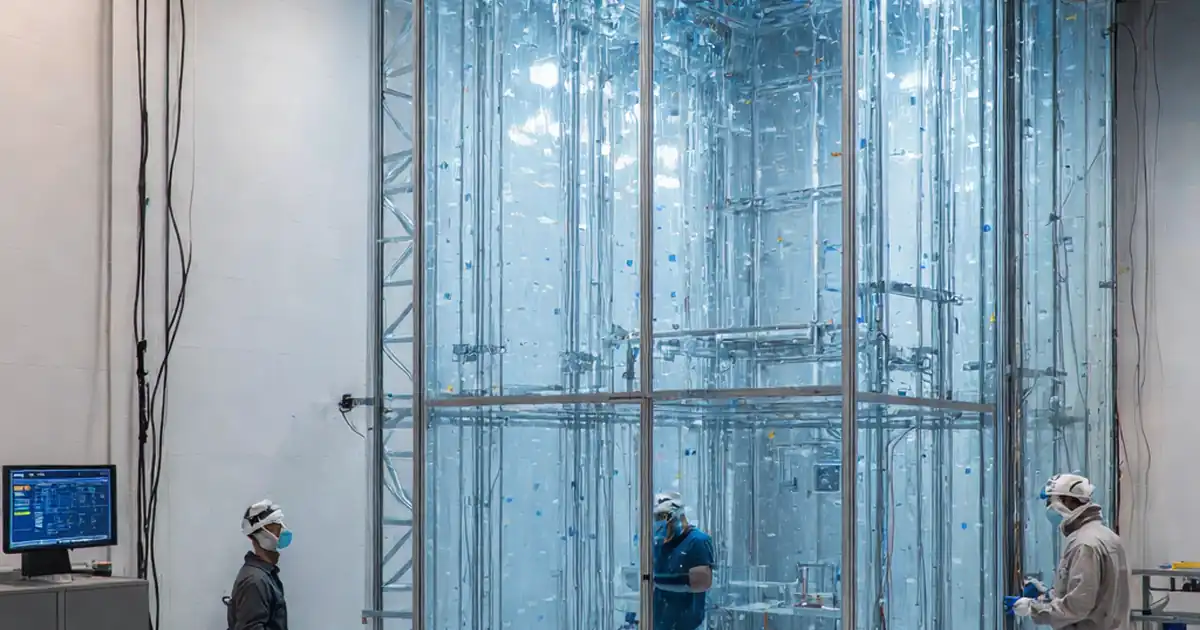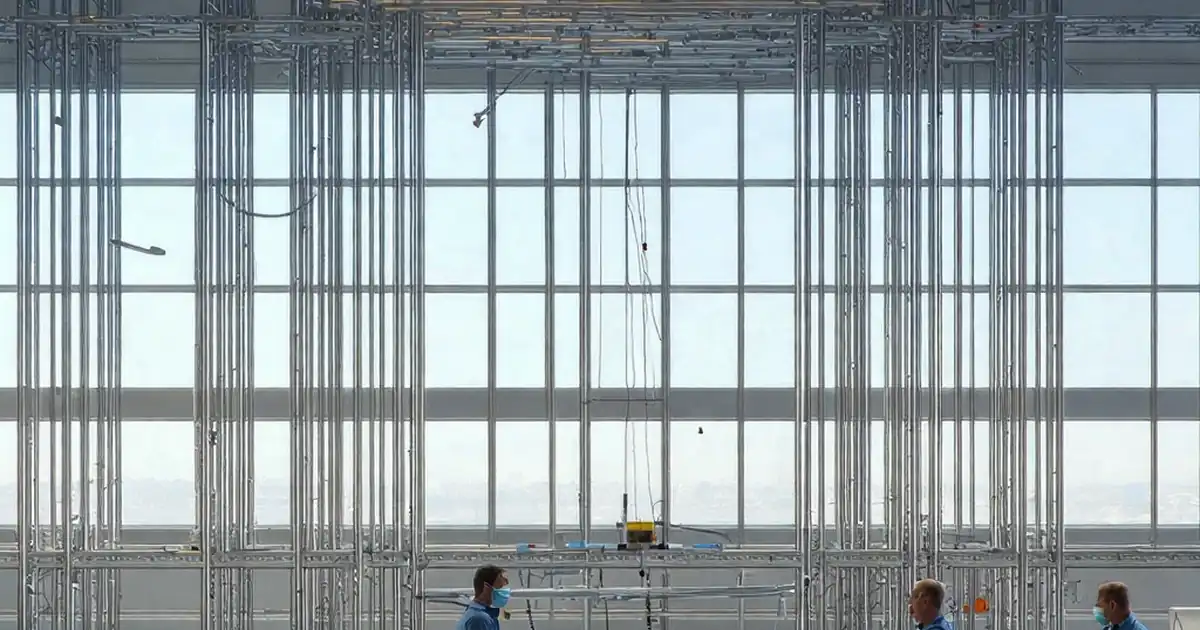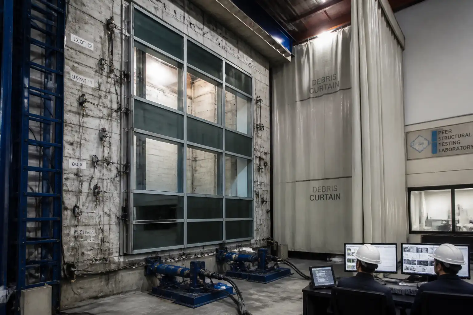
Inspection and Test Plan for Method Statement: Structural Performance Testing of Facade Mock-Up
AI-assisted inspection and test plan connected to a method statement, with PDF and Excel export.
More than a static template
Unlike a downloadable Word or PDF template, this ITP is an AI-assisted editable starting point directly connected to its method statement. Every inspection activity, hold point, and acceptance criterion is structured and ready to adapt to your project.
- AI-assisted customization — Tailor inspection activities and acceptance criteria to your specific project scope.
- Linked method statement — This ITP is connected to the corresponding method statement describing the work sequence.
- Multiple export formats — Download as a formatted PDF or editable Excel spreadsheet.
- Editable starting point, not a final document — Review and verify all content against your project specifications and standards before use.
What you can customize
When you save this ITP to your account, every inspection row becomes editable. You can add, remove, or modify:
- Inspection activity — Description of what is being inspected.
- Inspection type — Hold point (H), Witness point (W), Review (R), or Monitor (M).
- Responsibility — Contractor, subcontractor, engineer, or client.
- Frequency — How often the inspection occurs.
- Acceptance criteria — Referenced standard or specification requirement.
- Records — Forms, test reports, or checklists required as evidence.
Why this ITP is used
To ensure critical checks are witnessed and recorded, demonstrating compliance with project specifications and international standards.
Who uses this inspection and test plan
The test laboratory, main contractor, facade subcontractor, and Engineer/Consultant use the ITP to control and verify testing.
When this ITP is prepared and submitted
Applied before, during, and after all structural performance tests of the facade mock-up, from setup through final sign-off.
Who receives or approves this ITP
Engineer/Consultant for review and approval before testing commences.
Inspection scope
Covers documentation and calibration review, mock-up verification, instrumentation, chamber integrity, wind serviceability and strength tests, glass stress checks, anchor pull-out, cyclic racking, and post-test inspection.
Typical hold, witness, and review points
HP1 Pre-test readiness; HP2 Wind test plan confirmation; HP3 Racking protocol and fixture; HP4 Anchor test setup; HP5 Post-test review and sign-off.
Typical inspection records
ITP checklists, calibration registers, data plots, load–displacement curves, deflection tables, stress calculations, photos/videos, NCRs, and final report.
Important approval note
This ITP is an AI-assisted editable starting point, not a pre-approved document. Before use on any project, all inspection activities, hold points, and acceptance criteria must be reviewed and approved by the relevant parties (superintendent, principal contractor, or client representative) in accordance with your contract and project quality plan.
Always verify acceptance criteria against your applicable drawings, specifications, and regulatory requirements. Hold points must be confirmed with the relevant authority before work proceeds past that point.
Inspection and test plan
| Activity | Inspection / Test | Acceptance Criteria | Responsibility | Record |
|---|---|---|---|---|
| Pre-test documentation and calibration review | Verify certificates (ISO 17025), expiry dates, and sensor ranges | All equipment within calibration; ranges adequate for target loads | Lead Test Engineer / Engineer Representative | ITP checklist; calibration register |
| Mock-up dimensional verification | Measure key spans and panel alignments | Within approved drawing tolerances [Verify] | Lead Test Engineer / Facade Subcontractor | Dimension log; as-built sketch |
| Instrumentation installation/zeroing | Shunt/zero checks; DAQ time sync | Stable baseline; drift within ±0.1 mm over 10 min | Instrumentation Engineer | Zero log; time-sync record |
| Chamber integrity/leak check | Low-pressure hold/decay | Decay ≤ allowable [Verify] | Lead Test Engineer | Leak test report |
| Wind serviceability test (±P_s) | ASTM E330/EN 13116 pressure application and deflection logging | Member deflection within limits; no damage | Lead Test Engineer / Engineer Witness | Service test data/plots; photos |
| Wind strength test (±1.5×P_s) | ASTM E330 strength protocol | No breakage; residual set within spec | Lead Test Engineer / Engineer Witness | Strength test data; residual set log |
| Glass stress/strain measurement | Strain logging and stress calculation | Stresses ≤ design capacity per ASTM E1300 [Verify] | Instrumentation Engineer | Stress calc sheets; plots |
| Anchor proof and ultimate tests | ASTM E488 procedures; load vs displacement | Proof displacement within limits; ultimate ≥ required capacity [Verify] | Lead Test Engineer / Engineer Witness | Load–displacement curves; photos |
| Cyclic racking/seismic simulation | AAMA 501.4/501.6 cycling protocol | No glass fallout; retention and anchorage maintained; operables functional | Lead Test Engineer / Engineer Witness | Racking logs; drift response; video |
| Post-test inspection and sign-off | Visual/dimensional checks post-loading | Damage within allowable categories or NCR raised | Lead Test Engineer / Engineer Representative | Inspection checklist; sign-off sheet |
This table is a read-only public reference. Download the PDF or Excel version, or customize this ITP to edit it for your project.
Frequently asked questions
Related method statement
This Inspection and Test Plan is associated with the Method Statement: Structural Performance Testing of Facade Mock-Up method statement, which describes the step-by-step construction sequence, resources, materials, equipment, safety controls, and environmental controls for this activity.
View the Method Statement: Structural Performance Testing of Facade Mock-Up method statement →Continue with related inspection, method statement, article, and checklist resources.