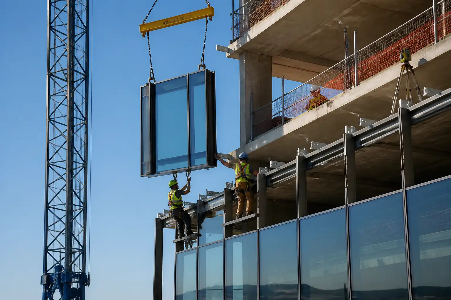
Inspection and Test Plan for Method Statement: Stick-Built Aluminium Curtain Wall Construction
AI-assisted inspection and test plan connected to a method statement, with PDF and Excel export.
More than a static template
Unlike a downloadable Word or PDF template, this ITP is an AI-assisted editable starting point directly connected to its method statement. Every inspection activity, hold point, and acceptance criterion is structured and ready to adapt to your project.
- AI-assisted customization — Tailor inspection activities and acceptance criteria to your specific project scope.
- Linked method statement — This ITP is connected to the corresponding method statement describing the work sequence.
- Multiple export formats — Download as a formatted PDF or editable Excel spreadsheet.
- Editable starting point, not a final document — Review and verify all content against your project specifications and standards before use.
What you can customize
When you save this ITP to your account, every inspection row becomes editable. You can add, remove, or modify:
- Inspection activity — Description of what is being inspected.
- Inspection type — Hold point (H), Witness point (W), Review (R), or Monitor (M).
- Responsibility — Contractor, subcontractor, engineer, or client.
- Frequency — How often the inspection occurs.
- Acceptance criteria — Referenced standard or specification requirement.
- Records — Forms, test reports, or checklists required as evidence.
Why this ITP is used
To ensure each critical step is inspected and tested against defined acceptance criteria for safety, durability, and performance.
Who uses this inspection and test plan
Site engineers, QA/QC inspectors, facade supervisors, third-party testers, and the Engineer/Client representative.
When this ITP is prepared and submitted
From setting out through final handover, with hold points at anchors, first bay, glazing, and field tests.
Who receives or approves this ITP
Engineer/Client Representative for review and approval.
Inspection scope
Dimensional control, anchor installation and testing, assembly tolerances, torque, sealant adhesion, drainage verification, and field air/water testing.
Typical hold, witness, and review points
Substrate acceptance, first anchors, first bay plumb/level, first lite glazing, torque audit, sealant adhesion test, field test bays.
Typical inspection records
Survey reports, anchor logs and test certificates, torque sheets, inspection checklists, sealant batch/adhesion reports, field test reports, as-built drawings.
Important approval note
This ITP is an AI-assisted editable starting point, not a pre-approved document. Before use on any project, all inspection activities, hold points, and acceptance criteria must be reviewed and approved by the relevant parties (superintendent, principal contractor, or client representative) in accordance with your contract and project quality plan.
Always verify acceptance criteria against your applicable drawings, specifications, and regulatory requirements. Hold points must be confirmed with the relevant authority before work proceeds past that point.
Inspection and test plan
| Activity | Inspection / Test | Acceptance Criteria | Responsibility | Record |
|---|---|---|---|---|
| Setting out and substrate acceptance | Dimensional survey vs. control grid | Within specified tolerances; substrate suitable and clean; benchmarks verified | Site Engineer / QA-QC / Engineer | Survey report; ITP checklist SE-01 |
| Anchor drilling and hole preparation | Hole diameter/depth/cleanliness verification | Per ETA and design; brush–blow sequence completed; no spalling or voids | QA-QC / Supervisor | Anchor hole log AN-01, photos |
| Anchor installation and proof load testing | Proof load to specified value; torque check for mechanical anchors | No slip >1.0 mm; no failure; torque within ±10% of spec | Third-Party Tester / QA-QC | Test report AN-PLT, torque sheet AN-TQ |
| Bracket installation and alignment | Laser/level check; fastener torque | Plumb/level ±2 mm over 3 m; projection ±2 mm; torque within ±10% | QA-QC / Supervisor | Bracket checklist BR-01; torque sheet BR-TQ |
| Mullion plumb and fixing | Plumb measurement; splice gap verification | ±2 mm/m; max 6 mm over 10 m; expansion gaps per drawings | QA-QC / Engineer | Mullion inspection MU-01 |
| Transom level and drainage orientation | Level check; verify drainage slots | Level ±2 mm/3 m; correct slot orientation; paths unobstructed | QA-QC / Supervisor | Transom inspection TR-01 |
| Gaskets, setting blocks and spacers | Continuity and hardness check; position of blocks | Continuous gasket; Shore A 85 ±5; blocks at quarter points | QA-QC | Gasket/blocks checklist GK-01 |
| Glazing insertion | Clearance/bite check; edge condition | Clearance 6–10 mm; bite ≥10 mm or 25% t; no edge damage beyond limits | QA-QC / Engineer | Glazing checklist GL-01, photos |
| Pressure plate torque and spacing | Torque audit with calibrated wrench | Within specified torque ±10%; spacing per drawings | QA-QC / Supervisor | Torque audit PP-TQ, calibration certs |
| Sealant application and adhesion | ASTM C1521 field adhesion tests; visual finish | Predominantly cohesive failure; smooth tooled finish; no voids | QA-QC / Sealant Manufacturer Rep (if required) | Sealant adhesion report SL-ADH; batch records |
| Drainage/weep verification | Visual and localized water pour | Free flow to exterior; slots per system; baffles/screens installed | QA-QC | Weep inspection DR-01 |
| Field performance tests (air/water) | ASTM E783/E1105; AAMA 501.2 where specified | Meets project performance criteria; no water beyond interior plane | Third-Party Tester / Engineer | Certified test reports FT-01 |
| Final inspection and handover | Visual, functional checks, documentation review | Defect-free installation; records complete; O&M/warranties submitted | Engineer / QA-QC / Client Rep | Completion certificate, snag list close-out |
This table is a read-only public reference. Download the PDF or Excel version, or customize this ITP to edit it for your project.
Frequently asked questions
Related method statement
This Inspection and Test Plan is associated with the Method Statement: Stick-Built Aluminium Curtain Wall Construction method statement, which describes the step-by-step construction sequence, resources, materials, equipment, safety controls, and environmental controls for this activity.
View the Method Statement: Stick-Built Aluminium Curtain Wall Construction method statement →Continue with related inspection, method statement, article, and checklist resources.