Method Statement – Aluminium Window Installation Works – Method Statement
AI-assisted method statement with matching ITP, PDF download, and Excel export.
More than a static template
Unlike a downloadable Word or PDF template, this method statement is an AI-assisted editable starting point connected directly to a matching Inspection and Test Plan. Every section is structured, project-adaptable, and ready to export.
- AI-assisted drafting — Customize every section with AI for your specific project scope.
- Linked ITP — A matching inspection and test plan is generated alongside the method statement.
- Multiple export formats — Download as a formatted PDF or editable Excel spreadsheet.
- Editable starting point, not a final document — Review, verify, and adjust all content against your project requirements before use.
Static template vs. Quollnet workflow
| Feature | Static template | Quollnet |
|---|---|---|
| Project-specific content | Manual fill-in required | AI-assisted customization |
| Linked ITP | Separate document, no link | Matching ITP included |
| Export formats | Usually PDF only | PDF and Excel |
| Structured sections | Free-form layout | 13 standardized sections |
| Saved to your account | Local file only | Cloud-saved, reusable |
| Content accuracy | You verify everything | AI-assisted, you still verify |
| Cost | Often free but time-intensive | Free to customize and download |
What you can customize
When you save this method statement to your account, every section becomes editable. The following 13 sections are included:
- Scope — Defines the activity and its boundaries.
- References — Standards, specifications, and drawings.
- Responsibilities — Roles and accountabilities.
- Resources — Labour, plant, and equipment summary.
- Materials — Materials and compliance requirements.
- Equipment — Tools and equipment details.
- Prerequisites — Hold points and pre-conditions.
- Method sequence — Step-by-step construction sequence.
- Safety controls — HSE risk controls and PPE.
- Environmental controls — Environmental mitigation measures.
- QA/QC — Quality inspection and test requirements.
- ITP — Inspection and Test Plan table (has its own page).
- Attachments — Referenced drawings and documentation.
Why this method statement is used
This method statement is used to define and communicate the approved procedure for carrying out method statement – aluminium window installation works on site. It ensures the work is planned in advance, the correct resources and controls are in place, and all personnel understand responsibilities, sequence, quality requirements, and safety controls before work begins. It aligns site execution with the documented scope and acceptance expectations.
Who uses this method statement
This method statement is used by contractors, site supervisors, project engineers, QA/QC engineers, HSE officers, consultants, and client representatives. It serves as a shared reference for planning, execution, supervision, inspection, and approval of the activity on site.
When it is prepared and submitted
The method statement is prepared before the work activity starts and submitted as part of the pre-construction documentation package for review and approval.
Who reviews or approves it
The method statement is usually submitted to the client representative, consultant, resident engineer, or project management consultant for review and approval before the work commences.
Important approval note
This method statement is an AI-assisted editable starting point, not a pre-approved document. Before use on any project, all content must be reviewed and approved by the relevant parties (superintendent, principal contractor, or client representative) in accordance with your contract and project quality plan.
For example: if your specification requires a departure from a referenced standard, that departure must be documented and approved separately — this method statement will not capture that automatically. Always verify against your applicable drawings, specifications, and regulatory requirements.
Method statement content
Scope
Summary
This method statement covers the complete supply-and-install sequence for factory-fabricated aluminium window assemblies, including:
- Delivery, offloading, and storage inspections
- Substrate and opening verification
- Frame preparation, positioning, shimming, and temporary fixing
- Mechanical anchoring to structure
- Perimeter sealing, vapour/air/water interface tie-ins (sill pan/end dams)
- Glazing installation or verification where pre-glazed
- Protection and cleaning
- Dimensional and tolerance checks
- QA/QC inspections, hold/witness points
- Field water penetration tests and air leakage checks prior to final acceptance
Works apply to new build and refurbishment projects and interface with adjacent façade, waterproofing, fire-stopping, and interior finishes. Project-specific values shall be verified per approved drawings and specifications.
Exclusions
- Structural design of openings and lintels
- Curtain wall systems (unless explicitly included)
- Permanent scaffolds and primary access systems
- Fire-stopping beyond perimeter fire barrier around frames (if required, separate method)
Constraints
- Do not install sealants below manufacturer’s minimum substrate/ambient temperature or on wet/contaminated surfaces.
- Avoid drilling into post-tensioned cables, embedded services, or reinforcement without approved permits and scanning.
References
| Document Type | Reference / Number | Revision | Notes |
|---|---|---|---|
| BS 8213-4: Windows and doors — Installation | General installation guidance and tolerances [Verify per project specs] | ||
| BS EN 14351-1: Windows and doors — Product standard, performance characteristics | CE/UKCA conformity and DoP for windows | ||
| BS EN 1026 / 1027 / 12207 / 12208 | Air permeability and water tightness test methods and classifications | ||
| ASTM E2112 | Installation of Exterior Windows, Doors and Skylights (best practices) | ||
| ASTM E1105 / AAMA 502 | Field water penetration testing of installed windows | ||
| ASTM E783 | Field measurement of air leakage through installed windows | ||
| ASTM C920 / ASTM C1193 / ASTM C1521 | Sealant specification, joint design, and field adhesion testing | ||
| BS EN 1279 / BS EN 12150 / BS EN 572 | Insulating glass units, toughened safety glass, and float glass standards | ||
| ISO 9001 / ISO 14001 / ISO 45001 | Quality, environmental, and occupational H&S management systems [Verify per project HSE plan] |
Responsibilities
| Role | Responsibility | Name / Party |
|---|---|---|
| Contractor’s Project Manager | Overall coordination, approvals, method compliance, ITP execution, liaison with Engineer/Consultant. | Main Contractor |
| Site Engineer / Construction Manager | Daily supervision, setting out, sequence control, workmanship, verification of tolerances, hold/witness point coordination. | Main Contractor |
| Aluminium Window Installer (Specialist Subcontractor) | Install frames, anchors, sealants, glazing per drawings and manufacturer instructions. | Specialist |
| HSE Manager / Officer | HSE plan implementation, task-specific risk assessments, permits, toolbox talks, inspections. | Main Contractor |
| QA/QC Engineer | Incoming materials inspection, records, calibrations, test coordination, NCR management, handover dossier. | Main Contractor |
| Engineer / Consultant / Client Representative | Inspection at notified hold/witness points, review of test results, acceptance/rejection. | Employer |
Resources
| Resource Type | Description | Quantity | Remarks |
|---|---|---|---|
| Labour | As scheduled [Verify per project] | ||
| Staff | 1 per active front | ||
| Staff | Shared / 1 per shift | ||
| Staff | Shared / 1 per shift |
Materials
| Material | Specification / Grade | Quantity | Remarks |
|---|---|---|---|
| Aluminium window frames, sashes, sub-frames | BS EN 755 (extrusions), Finish per AAMA 2603/2604/2605 as specified | ||
| Glazing units | BS EN 1279 (IGU), BS EN 12150 (toughened), BS EN 14449 (laminated) | ||
| Sealant | ASTM C920, Class 25 or higher; ASTM C1248 (non-staining) | ||
| Backer rod | ASTM C1330 Type C (closed-cell) | ||
| Setting blocks / spacers / shims | Compliant with BS 6262 recommendations [Verify] | ||
| Mechanical anchors / screws | ASTM E488 (testing), A2/A4 SS grade as specified | ||
| Sill pan flashing and waterproofing membrane | ASTM D1970 (SA membrane) or equivalent; compatibility-confirmed | ||
| Primers, cleaners, setting tapes, gaskets | Per manufacturer; compatibility-tested (ASTM C1087) [Verify] |
Equipment
| Equipment | Capacity / Type | Quantity | Inspection Required |
|---|---|---|---|
| Laser level / digital level | ±1 mm @ 10 m or better | ||
| Rotary hammer drill with dust extraction | SDS-Plus/Max, variable speed | ||
| Torque wrench | 5–50 N·m range [Verify per fastener] | ||
| Glazing suction cups / lifters | Rated > glass panel weight, inspected daily | ||
| Sealant guns (manual/pneumatic) and tooling spatulas | Compatible with sealant type | ||
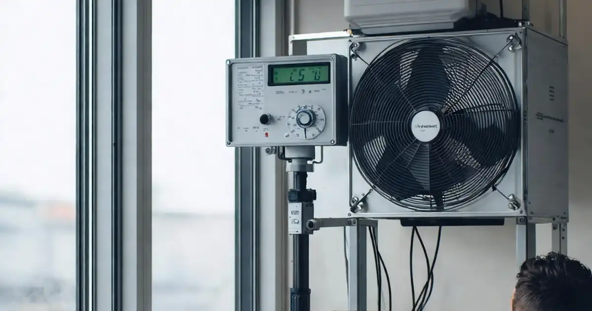
| Calibrated spray rack & pressure chamber | ASTM E1105 compliant, 3.4 L/(m²·min) flow [Verify] | ||
| Access equipment (MEWP/tower scaffold) | Certified, inspected [Verify per local regs] |
Prerequisites
Approvals and Documentation
- Approved shop drawings, manufacturer instructions, sealant compatibility letters, test certificates (DoP/CE/UKCA), and finishes approvals.
- Approved ITP with defined hold and witness points.
Site Readiness
- Openings surveyed and within tolerance: reveal dimensions vs. frame size allowing uniform perimeter gap typically 5–12 mm [Verify per project]; substrate sound, clean, dry.
- Sill pan details approved; interface membranes and end dams available.
- Access, lifting paths, and work-at-height systems in place and certified.
Materials & Equipment
- Materials delivered with identification, protected from damage; storage off ground, dry, flat. Glass stored on A-frames with edge protectors.
- Calibrations in date: torque wrench, spray rack, pressure gauges, levels.
HSE & Permits
- Task-specific RA/MS approved; permits: work at height, lifting, hot works (if any), drilling into structure after scan results.
- Utilities and post-tension locations confirmed by scan and approved by Engineer.
Environmental/Weather
- No installation of sealants in rain or when substrate temperature below manufacturer’s minimum (typically ≥5°C) or above maximum (typically ≤40°C) [Verify]. Surface moisture < 5% for adhesion-critical interfaces [Verify].
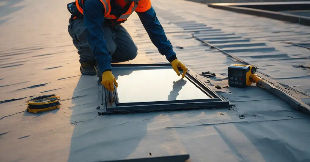
Method Sequence
| Step | Activity | Description | Responsibility | Inspection / Hold Point |
|---|---|---|---|---|
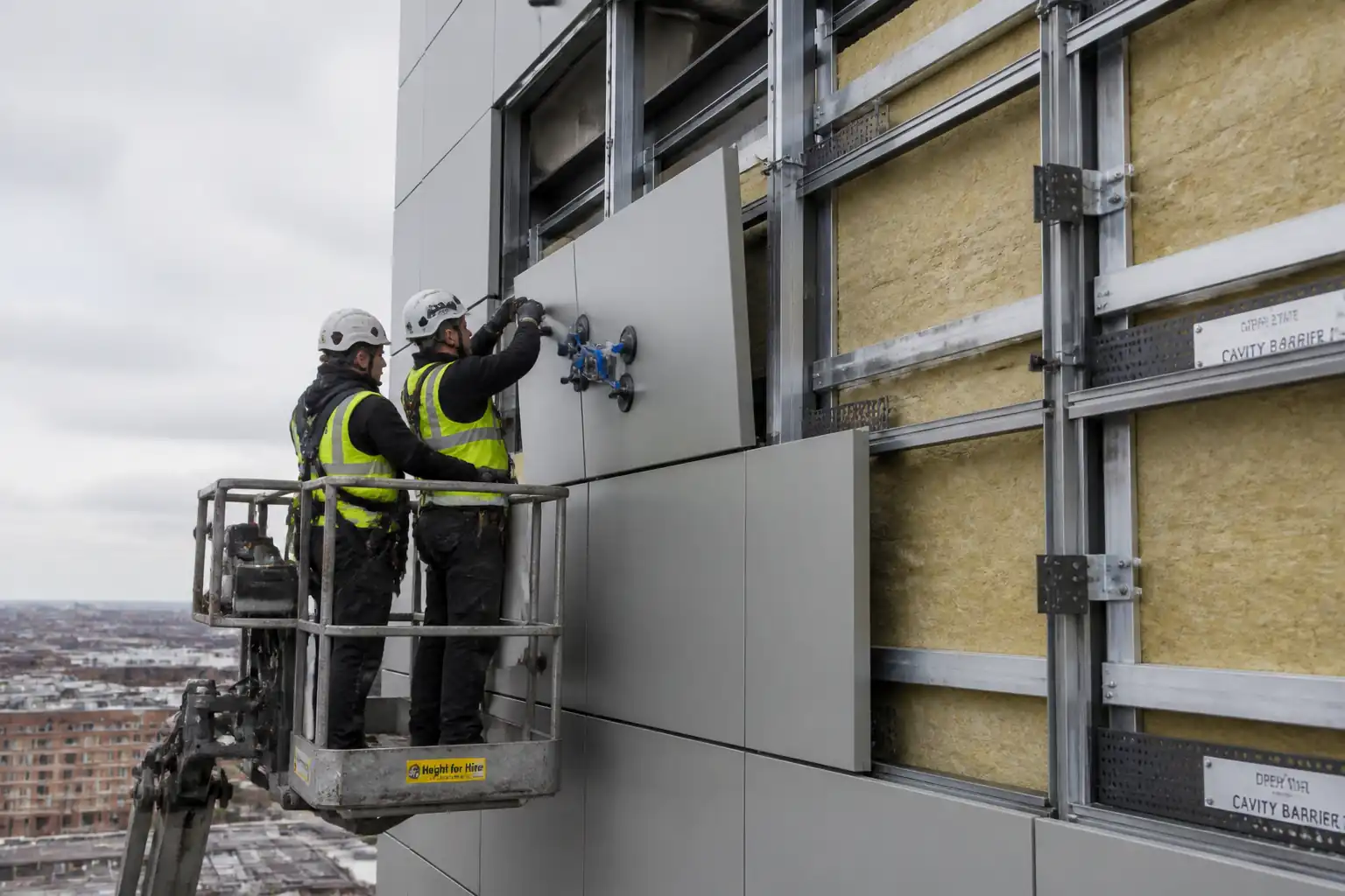
| 1 | Delivery and Offloading Inspection (HOLD) | Inspect frames, sashes, glazing, gaskets, hardware on arrival; verify DoP/CE/UKCA, finishes, sizes, and quantities; record damages. | QA/QC with Installer | Visual check, finish thickness spot-check if required |
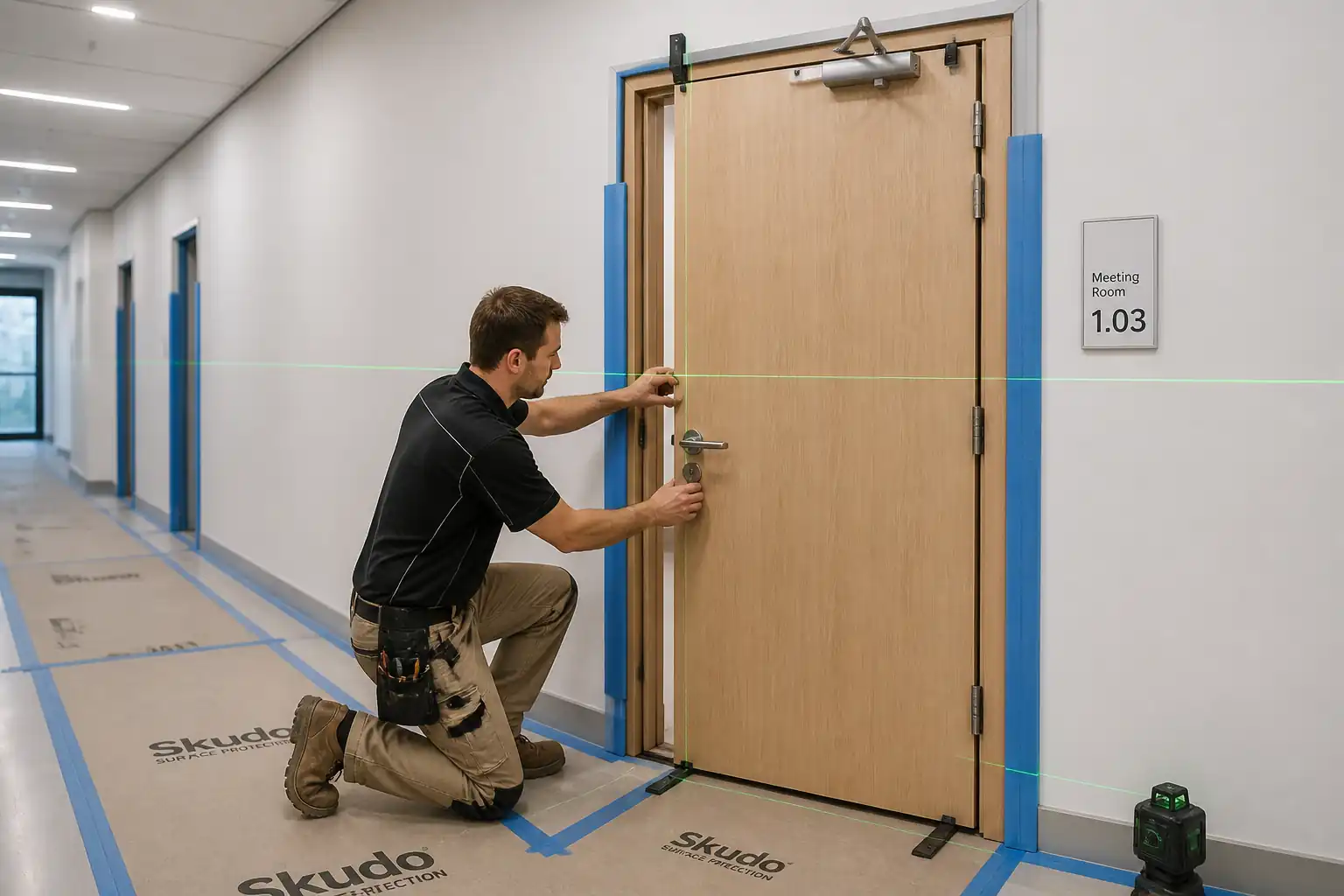
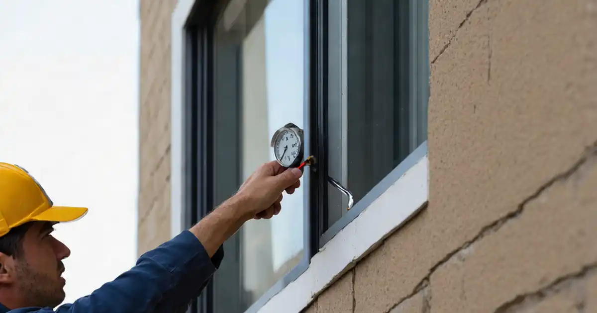
| 2 | Opening Survey & Substrate Verification (HOLD) | Measure opening size, squareness, plumb/level; check substrate integrity; confirm allowance for shims and sealant joint. | Site Engineer | Measure with laser and tapes; substrate tap test |
| 3 | Sill Pan and End Dams Installation (WITNESS) | Install pre-formed or membrane sill pan with upstands ≥25 mm and sealed end dams; slope to exterior (≥2%). | Installer | Visual; adhesion check; continuity to adjacent WRB/air barrier |
| 4 | Frame Preparation | Remove transport blocks; fit setting blocks, packers, temporary braces; pre-drill fixing holes per layout. | Installer | Check component completeness |
| 5 | Frame Positioning & Temporary Fixing (WITNESS) | Place frame in opening on setting blocks; align plumb/level/square; insert non-compressible shims at anchor points. | Installer with Site Engineer | Instrument check |
| 6 | Mechanical Anchoring to Structure (HOLD) | Drill substrate, clean holes; install specified anchors/screws; tighten to torque; corner fixings first then intermediates. | Installer | Hole cleanliness; embedment depth; corrosion class |
| 7 | Anchor Proof / Pull-Out Testing (WITNESS) | Perform on-site proof testing where specified on first-of-type and sampling thereafter. | QA/QC with Third Party (if required) | Setup witness by Engineer |
| 8 | Perimeter Air/Vapour Barrier Tie-in | Install interior air/vapour seal or membrane (if specified) continuous to adjacent wall/WRB; terminate to frames as detailed. | Installer | Continuity and adhesion |
| 9 | Perimeter Backer Rod & Primary Sealant (WITNESS) | Install backer rod; apply sealant with proper bead size and tooling to achieve adhesion to two sides only. | Installer | Bead continuity; joint geometry; cleanliness |
| 10 | Sealant Field Adhesion Test | Conduct field adhesion testing on fresh sealant beads using peel or probe method. | QA/QC | Witness by Engineer if required |
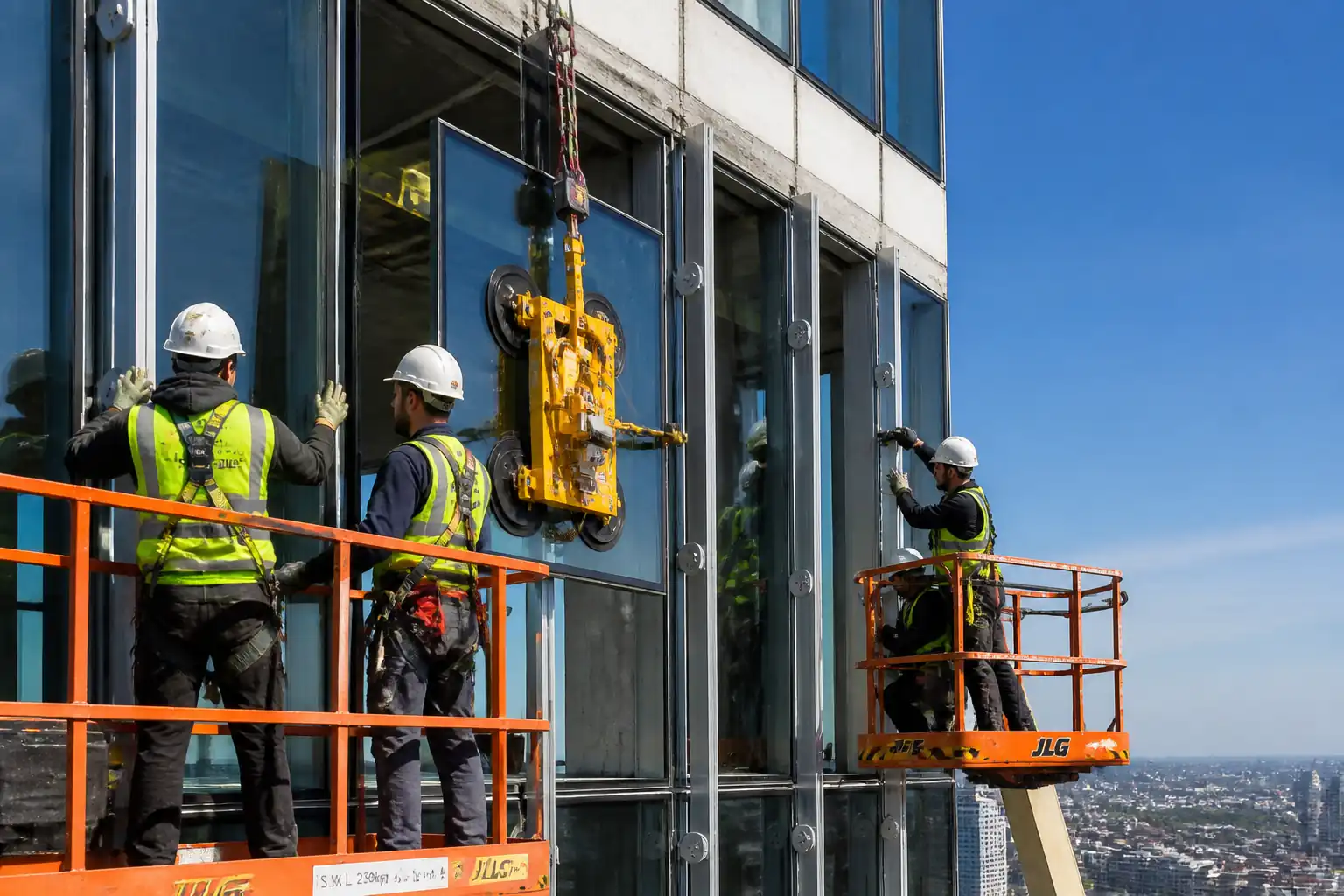
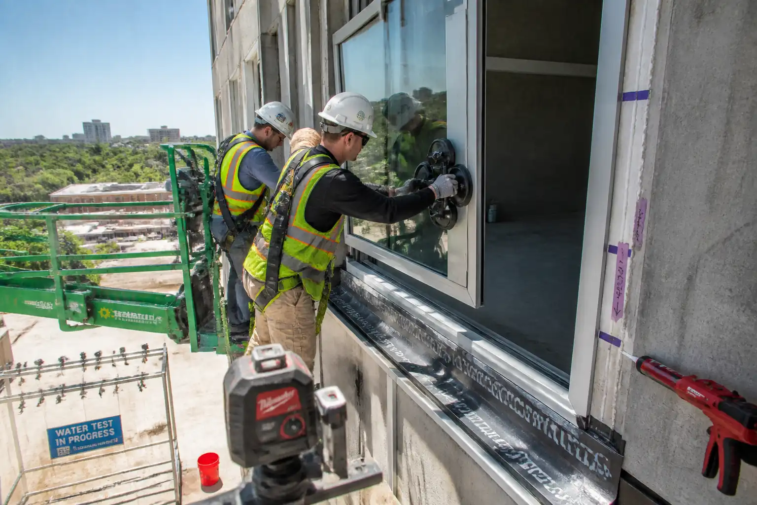
| 11 | Glazing Installation / Verification (WITNESS) | Install glazing into frames: place setting blocks at 1/4 points; insert gaskets/glazing beads; ensure correct bite and clearances. | Installer | Visual; gauge measurement |
| 12 | Drainage/Weep Verification | Check sill weep holes clear; test with trickle water to confirm discharge to exterior. | Installer | Water trickle test |
| 13 | Hardware and Operation Check | Fit/adjust handles, locks, restrictors; verify smooth operation, engagement, and safety restrictors where required. | Installer | Function test |
| 14 | Protection & Cleaning | Apply protective films/boards; clean frames using non-abrasive cleaners; remove sealant smears without damaging finish. | Installer | Visual |
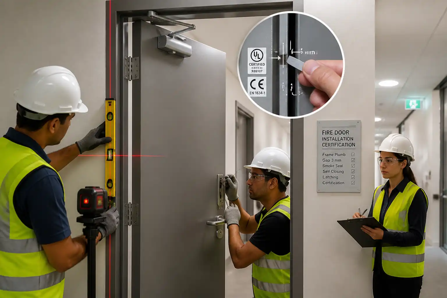
| 15 | Dimensional & Tolerance Survey (HOLD) | Final check of installed frame: plumb/level/square, reveal gaps, face alignment to façade; document measurements. | Site Engineer / QA | Instrument survey |
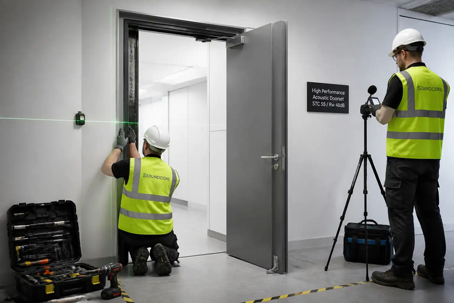
| 16 | Field Water Penetration Test (WITNESS) | Conduct ASTM E1105 (or BS EN 1027) on first-of-type and sampling; chamber pressure and spray per spec. | Third-party/QA with Engineer | Witnessed by Engineer |
| 17 | Field Air Leakage Test (if specified) | Perform field air leakage per ASTM E783 (or BS EN 1026) on sample units. | Third-party/QA | Witness by Engineer if required |
| 18 | Snag Rectification and Sealant Cure | Rectify defects; allow sealant to cure to handling strength before removing protections as instructed. | Installer | Re-inspection of snags |
| 19 | Final Inspection & Handover (HOLD) | Joint inspection with Engineer for final acceptance, O&M submission, warranties, as-builts. | Contractor PM / QA with Engineer | Visual and records review |
Health, Safety, and Environment – Safety Controls
Task-Specific Hazards and Controls
1) Hazard: Work at height (MEWP/tower near openings)
- Likely consequence: Fall from height causing serious injury/fatality.
- Engineering/procedural control: Use certified MEWP or tower scaffold with guardrails; install temporary edge protection or fall-arrest systems; exclude zones below.
- Required PPE: Full body harness with lanyard for MEWP, hard hat, gloves, safety boots, eye protection.
- Collective preventive measure: Guardrails, toe-boards, debris nets as applicable.
- Inspection/permit/supervision: Work-at-height permit; daily MEWP inspection; competent operator certification [Verify per project HSE plan and local regulations].
2) Hazard: Manual handling of frames/glass
- Likely consequence: Musculoskeletal injury, crush injuries, glass breakage/cuts.
- Engineering/procedural control: Team lifts, rated suction lifters, mechanical aids; plan lifts; keep hands clear of pinch points; use glass edge protectors.
- PPE: Cut-resistant gloves (EN 388 level appropriate), forearm protection, safety boots with toe caps, eye protection.
- Collective measure: Designated lifting routes, clear floors, spotter.
- Inspection/permit/supervision: Lifting plan/briefing; equipment inspection tags; supervisor oversight.
3) Hazard: Drilling into structure and hidden services/PT
- Likely consequence: Electric shock, flooding, structural damage, cable strike.
- Control: GPR/ferroscan and permits; marked exclusion zones; drill stops for depth; approved anchor locations from drawings.
- PPE: Dielectric gloves as required, eye/ear protection, dust mask (P2/P3 if masonry drilling).
- Collective measure: Lock-out/tag-out of known circuits; barriers.
- Inspection/permit/supervision: Permit to drill; scan records attached; competent person supervision.
4) Hazard: Falling materials (beads, tools, glass)
- Likely consequence: Injuries to persons below, property damage.
- Control: Tool lanyards; exclusion zones; debris nets where required; secure components until fixed.
- PPE: Hard hats, safety footwear, eye protection.
- Collective measure: Barricades and signage; spotter control.
- Inspection/permit/supervision: Daily prestart inspection; supervisor to enforce drop zones.
5) Hazard: Sealant/cleaner chemical exposure (VOCs)
- Likely consequence: Dermatitis, respiratory irritation, eye injury.
- Control: Use low-VOC products; ventilation; follow SDS; avoid mixing incompatible chemicals.
- PPE: Nitrile gloves, safety glasses/goggles, RPE where indicated by SDS.
- Collective measure: Local exhaust/air movement in enclosed spaces.
- Inspection/permit/supervision: SDS on site; COSHH assessment; HSE inspection.
6) Hazard: Noise and vibration from drilling
- Likely consequence: Hearing loss, HAVS.
- Control: Low-vibration tools; time limits; damping pads; pre-drill where feasible.
- PPE: Hearing protection (SNR per risk), anti-vibration gloves.
- Collective measure: Rotating tasks to limit exposure.
- Inspection/permit/supervision: Noise survey; HAV monitoring records.
7) Hazard: Glass breakage during installation
- Likely consequence: Lacerations, falling shards.
- Control: Use toughened/laminated glass per drawings; maintain edge clearances; avoid point loads; store on stable A-frames.
- PPE: Cut-resistant gloves, face shield during risky maneuvers.
- Collective measure: Exclusion zone during glazing.
- Inspection/permit/supervision: Pre-use inspection of glass; supervisor authorization for large panes.
8) Hazard: Weather exposure (wind/rain)
- Likely consequence: Loss of control of panels, poor sealant adhesion.
- Control: Cease lifts in winds above manufacturer/plan limit (e.g., >10–12 m/s) [Verify]; postpone sealant works in rain.
- PPE: Weather-appropriate PPE; anti-slip footwear.
- Collective measure: Wind monitoring; temporary covers.
- Inspection/permit/supervision: Supervisor decision log; anemometer readings.
9) Hazard: Silica/alkali dust when drilling masonry
- Likely consequence: Respiratory illness, eye injury.
- Control: On-tool extraction, wet suppression where permitted; vacuum class M/H.
- PPE: RPE (P2/P3), goggles.
- Collective measure: Local exhaust, area segregation.
- Inspection/permit/supervision: Dust control plan; equipment PAT and extraction testing.
10) Hazard: Pinch points when inserting beads/hardware
- Likely consequence: Finger injuries.
- Control: Use proper jigs; keep hands clear; progressive fixing sequence.
- PPE: Close-fitting gloves.
- Collective measure: Training and supervision.
- Inspection/permit/supervision: Toolbox talk; supervision checks.
Environmental Controls
Key Environmental Aspects and Controls
- Waste generation (packaging, offcuts, broken glass)
- Control: Segregate waste streams; recycle aluminium and glass via licensed recyclers; minimize packaging; record waste transfer notes.
-
Inspection/permit: Waste contractor license; site environmental inspections.
-
Sealant/cleaner VOCs and spills
- Control: Use low-VOC products; secondary containment for liquids; spill kits at point of use; no discharge to drains.
- PPE: Nitrile gloves, goggles.
-
Inspection/permit: SDS and COSHH assessment; spill response drill.
-
Noise and dust
- Control: Time works to avoid sensitive hours; on-tool extraction; acoustic screens if required; monitor dust (PM) where specified.
-
Inspection/permit: Noise/dust monitoring logs; community liaison as required.
-
Water use for testing (E1105)
- Control: Use calibrated spray rack; collect and drain water to designated points; prevent ingress to finishes.
-
Inspection/permit: Method approved; containment mats used.
-
Coating protection
- Control: Avoid abrasive cleaners; prevent alkaline mortar/screed contact; immediate wipe-down after contamination.
-
Inspection/permit: Daily visual checks; protection maintained until handover.
-
Transport and storage
- Control: Store under cover on bearers; prevent ground contamination; forklift drip trays if refueling nearby.
- Inspection/permit: Storage area inspection log.
Quality Assurance / Quality Control
Controls
- Use only approved manufacturers and batches with traceability.
- Calibrated instruments: torque wrenches, levels, pressure gauges, spray racks.
- ITP with defined HOLD/WITNESS points at delivery, opening survey, anchoring, sealing, glazing, water testing, and final acceptance.
Sampling and Testing
- Anchors: Proof tests on first-of-type and sampling thereafter (e.g., 3 per substrate type or 5%) [Verify].
- Sealant: Field adhesion tests per ASTM C1521, frequency 1 per day per substrate/sealant or 1/50 windows [Verify].
- Water penetration: ASTM E1105 (or BS EN 1027) on first-of-type each elevation and ≥5% thereafter [Verify].
- Air leakage: ASTM E783 (or BS EN 1026) if specified.
Tolerances (typical – verify per project)
- Frame plumb/level: ±2 mm per 1 m, ±3 mm overall height/width.
- Squareness (diagonal difference): ≤2–3 mm depending on size.
- Perimeter seal joint: Uniform width typically 6–12 mm; depth ≈ 1/2 width for silicones.
- Anchor spacing: First fixings 150–200 mm from corners; intermediate ≤400–600 mm.
- Glazing: Bite ≥6–10 mm; edge clearance 3–6 mm; setting blocks at quarter points.
Documentation and Handover
- Material Inspection Reports, Delivery notes, DoPs/CE/UKCA certificates.
- Anchor torque/pull test records, sealant adhesion test results.
- Water/air test reports, dimensional surveys, NCR/CAR logs.
- O&M manuals, warranties (e.g., finish, sealant, IGU), as-built drawings.
Nonconformance
- Record NCR, identify root cause, implement corrective action; retest affected units where applicable.
Attachments
- Approved shop drawings and installation details
- Manufacturer product data sheets and DoP/CE/UKCA certificates
- Sealant TDS, SDS, and compatibility letters
- Calibration certificates (torque wrench, spray rack, gauges)
- Anchor approvals and test data; pull test method statements
- Opening survey and setting-out drawings
- ITP with hold/witness points and checklists
- O&M manuals, warranties (finish, IGU, hardware)
- Risk assessments, permits, and toolbox talk records
This content is a read-only public reference. Download or customize to get an editable version.
ITP preview
The first inspection activities from the linked ITP for Method Statement – Aluminium Window Installation Works:
| Activity | Inspection / Test | Acceptance Criteria | Responsibility | Record |
|---|---|---|---|---|
| Delivery inspection of windows, glazing, and accessories (HOLD) | Visual, quantity/ID verification; finish inspection | Conforms to approvals; no damage; documentation complete | QA/QC Inspector; Witness: Engineer | MIR, photos |
| Opening survey and substrate verification (HOLD) | Dimensional and plumb/level checks | Within specified tolerances; substrate sound and clean | Site Engineer; Witness: Engineer | Survey sheet |
| Sill pan flashing and end dams (WITNESS) | Visual and adhesion check | Continuous, sloped to exterior, sealed corners | Installer; Witness: QA/QC/Engineer | Checklist, photos |
Showing 3 of 12 inspection activities. View full ITP →
Related Inspection and Test Plan
An Inspection and Test Plan (ITP) is available for Method Statement – Aluminium Window Installation Works. The ITP defines the inspection activities, acceptance criteria, hold and witness points, responsible parties, and records required to verify the work described in this method statement.
View the Method Statement – Aluminium Window Installation Works ITP →Frequently asked questions
Continue with related Quollnet resources connected to this method statement.