Test façade mock-up for seismic movement performance (where required)
Definition: Test façade mock-up for seismic movement performance where required verifies façade systems accommodate interstorey drift and racking, guiding designers, contractors, and QA inspectors through setup, instrumentation, cyclic displacement, and acceptance documentation.
- Proves drift accommodation, anchorage robustness, and glazing serviceability.
- Standardized setup, calibrated sensors, and clear evidence-driven acceptance.
- Reduces rework by catching failure modes before site installation.
- Interactive, commentable checklist; export PDF/Excel with QR code.
Test façade mock-up for seismic movement performance where required establishes whether the proposed façade assembly can accommodate interstorey drift and racking without loss of safety or serviceability. This guide covers seismic drift testing, curtain wall racking protocols, and movement joint verification for full-scale mock-ups representative of project details. The checklist focuses on preparation, instrumentation, cyclic displacement execution, and post-test assessment, avoiding adjacent scopes such as wind or rain penetration testing except where used as post-seismic verification. By following a structured, evidence-led approach—calibrated sensors, controlled waveforms, and measurable acceptance cues—teams reduce the risk of glass damage, sealant tearing, anchor distress, or operable hardware jamming. Outcomes include traceable data, photo documentation, and clear pass/fail judgements tied to the approved test plan, manufacturer instructions, and authority requirements. Start in interactive mode to tick items, attach comments, upload readings and photos, and then export to PDF/Excel with a secured QR code for audit.
- Validate façade drift tolerance, anchorage behavior, and functional performance before sitewide rollout. This mock-up protocol demonstrates how mullions, glazing, joints, and fixings respond to specified interstorey displacement cycles, reducing retrofit risk, shortening commissioning, and supporting approvals per approved project specifications and authority requirements with traceable data and images.
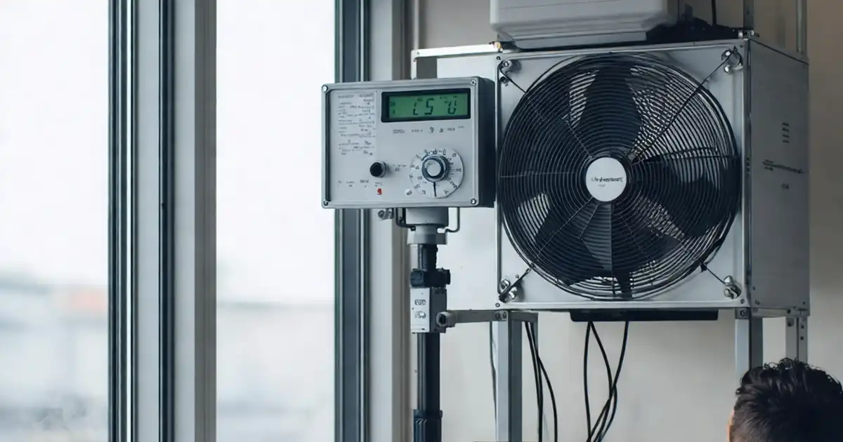
- Drive consistency with calibrated LVDTs, load cells, and synchronized data logging while applying controlled cyclic racking to target drift ratios. Acceptance cues include intact glazing, recoverable seals, secure anchors, and operable hardware forces within limits, supplemented by air leakage checks to confirm envelope integrity is substantially retained after seismic movement.
- Interactive online checklist with tick, comment, and export features secured by QR code.
- Produce a clear, defensible test record: signed test plan, rig capability evidence, sensor certificates, displacement/time plots, annotated damage maps, corrective actions, and sign-offs. Centralized archiving and QR authentication enable rapid retrieval during design reviews, contractor handover, insurer queries, or third-party conformity assessments.
Pre-Test Submittals & Setup
Mock-up Fabrication & Installation
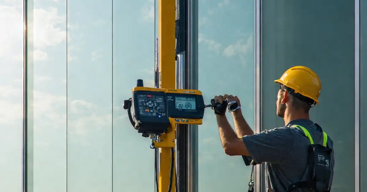
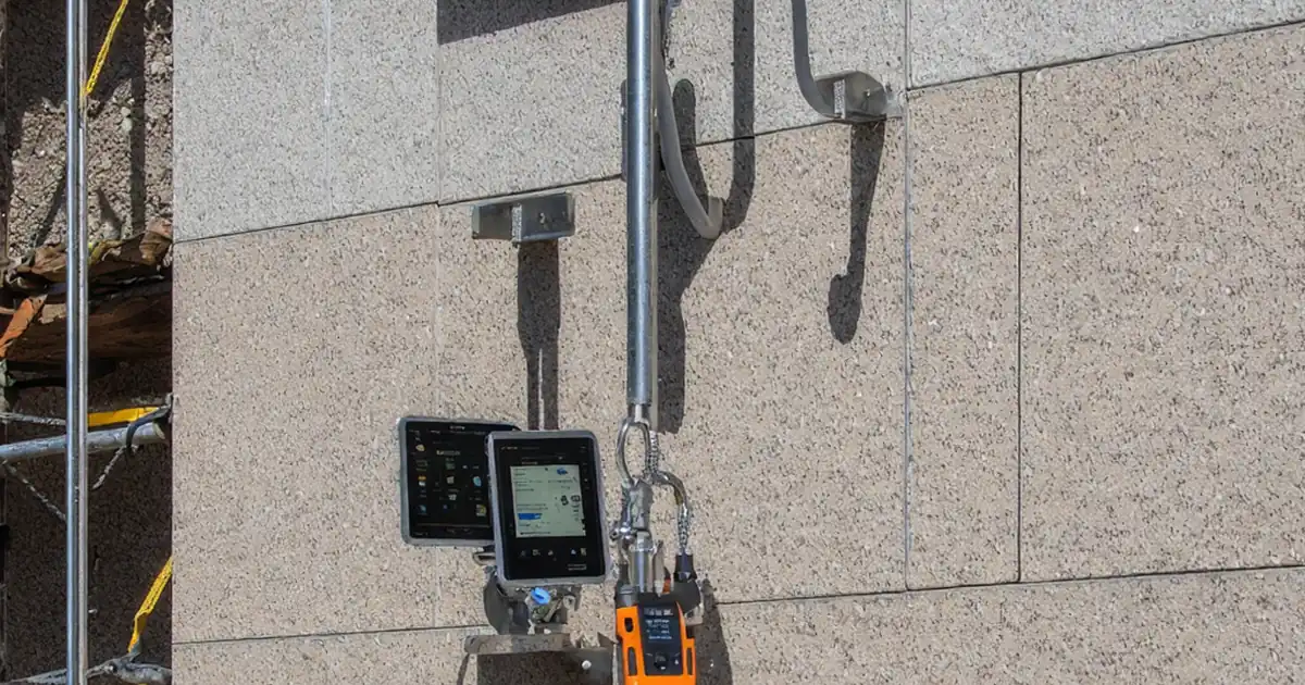
Instrumentation & Calibration
Seismic Displacement Testing
Post-Test Inspection & Documentation
Objectives, Scope, and Acceptance Cues
A seismic movement mock-up demonstrates that the façade system can accommodate specified interstorey drift without losing safety, weathertightness, or functionality. The scope here is a full-scale, representative assembly replicating anchors, joints, glazing, and interfaces likely to govern performance. Acceptance typically hinges on intact glazing, recoverable seals, un-compromised anchors, and functional operables after cyclic racking, supported by traceable measurements. Before testing, confirm the plan defines drift ratios, cycle counts, control waveform, and evidence requirements per approved project specifications and authority requirements. Avoid extending into unrelated tests unless they support post-seismic verification (e.g., air leakage trend). Use a single, consistent protocol to prevent mixed data. On completion, acceptance cues are compared against the plan and manufacturer tolerances. Clear documentation—plots, photos, and calibrated readings—enables defensible pass/fail decisions and informs any design refinements before sitewide deployment.
- Replicate anchors, joints, and glazing details that govern performance.
- Define drift ratios, cycles, and waveform in the test plan.
- Use calibrated sensors with traceable certificate numbers.
- Confirm acceptance cues with photos and plots.
- Keep protocol single and consistent for clean analysis.
Instrumentation, Control, and Data Quality
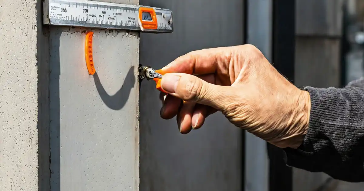
Reliable results depend on correct sensor placement and disciplined data control. LVDTs should capture storey drift and key mullion movements; strain gauges and accelerometers are added only where the plan requires them. Synchronize channels to within ±0.01 s and select sampling rates high enough to resolve the waveform. Conduct pre-conditioning cycles to stabilise fixtures and verify signal integrity. Apply cyclic racking to the target drift ratios using a controlled waveform and rate consistent with the plan. During holds at peak displacement, complete close inspections of glazing edges, sealant lines, and anchors, capturing high-resolution images. After cycles, run any specified functional checks and, if included, a post-racking air leakage test to assess envelope stability. Store raw data in open formats with channel maps, ensuring retraceability from plot to sensor.
- Zero sensors and verify stable baselines.
- Synchronize time bases for all channels.
- Control waveform, rate, and peak holds.
- Capture photos and videos at critical states.
- Export raw data with a clear channel map.
Post-Test Evaluation and Reporting
After cycling, compare all observations to the acceptance criteria. Identify and classify any damage such as sealant tearing, gasket displacement, glass chips, or anchor movement. Measure residual displacements to assess recovery and serviceability. Where increases in air leakage are specified, compare results to baseline values to confirm acceptable trends. Compile a comprehensive report detailing setup, environmental conditions, results, nonconformities, and corrective actions. Include displacement/time plots, annotated photos, and signatures. Reference applicable project specifications and authority requirements without citing specific clauses. Archive all records securely and generate a QR code that links stakeholders to the authenticated final dossier. This approach supports design validation, insurer scrutiny, and authority reviews.
- Classify and photo-document all observed damage.
- Measure and record residual displacements.
- Trend any air leakage change to baseline.
- List nonconformities with corrective actions.
- Archive with QR-linked authenticated records.
How to Use This Checklist
- Preparation: Confirm the approved test plan, rig capacity, and calibrated sensors. Assemble tools (LVDTs, DAQ, torque wrench, calipers), PPE, and materials. Replicate anchorage and joints per shop drawings, and brief the team on safety and roles.
- Using the Interactive Checklist: Open interactive mode, select your lot/mock-up ID, and work through sections in order. Tick items as completed, attach comments, photos, plots, and certificates, and tag issues for follow-up.
- Record and Review: Enter measured values (mm, N, Pa) directly into fields. Use time-stamped comments to document anomalies. Generate interim summaries to confirm coverage before moving to cyclic racking and post-test checks.
- Export and Share: When complete, export to PDF/Excel with embedded photos and readings. Share the file or a secure link with designers, contractors, and reviewers for timely feedback.
- Sign-Off and Archive: Capture digital signatures from responsible parties, finalize nonconformities and actions, then archive the record. A QR code secures authenticity and enables rapid retrieval during audits.

Call to Action
- Start Checklist Tick off tasks, leave comments on items or the whole form, and export your completed report to PDF or Excel—with a built-in QR code for authenticity.
- Download Excel - Façade Seismic Movement Mock-Up Test
- Download PDF - Façade Seismic Movement Mock-Up Test
- View Image - Façade Seismic Movement Mock-Up Test
Cite & Embed
“Façade Seismic Movement Mock-Up Test by Quollnet”
with a link to
this source page.

FAQ
Question: What drift ratios should a façade seismic mock-up test include?
Question: Do I need a full-scale mock-up or will a partial assembly suffice?
Question: How do I interpret glass cracks or sealant tears during testing?
Question: Can seismic movement testing be done on-site instead of in a lab?
Related Articles
Broader reading and guidance connected to this checklist topic.


Is It Important To Customize Your Qr Code And How To Do It?

Concrete Cube Test Register Excel Format – Pdf & Excel Sample

Rams Pack In Construction: Method Statement And Risk Assessment Template
Related Checklists
Keep the workflow moving with nearby templates chosen from similar checklist content.