
Method Statement: QA/QC Hold Points for Facade Alignment and Tolerance Verification – Method Statement
AI-assisted method statement with matching ITP, PDF download, and Excel export.
More than a static template
Unlike a downloadable Word or PDF template, this method statement is an AI-assisted editable starting point connected directly to a matching Inspection and Test Plan. Every section is structured, project-adaptable, and ready to export.
- AI-assisted drafting — Customize every section with AI for your specific project scope.
- Linked ITP — A matching inspection and test plan is generated alongside the method statement.
- Multiple export formats — Download as a formatted PDF or editable Excel spreadsheet.
- Editable starting point, not a final document — Review, verify, and adjust all content against your project requirements before use.
Static template vs. Quollnet workflow
| Feature | Static template | Quollnet |
|---|---|---|
| Project-specific content | Manual fill-in required | AI-assisted customization |
| Linked ITP | Separate document, no link | Matching ITP included |
| Export formats | Usually PDF only | PDF and Excel |
| Structured sections | Free-form layout | 13 standardized sections |
| Saved to your account | Local file only | Cloud-saved, reusable |
| Content accuracy | You verify everything | AI-assisted, you still verify |
| Cost | Often free but time-intensive | Free to customize and download |
What you can customize
When you save this method statement to your account, every section becomes editable. The following 13 sections are included:
- Scope — Defines the activity and its boundaries.
- References — Standards, specifications, and drawings.
- Responsibilities — Roles and accountabilities.
- Resources — Labour, plant, and equipment summary.
- Materials — Materials and compliance requirements.
- Equipment — Tools and equipment details.
- Prerequisites — Hold points and pre-conditions.
- Method sequence — Step-by-step construction sequence.
- Safety controls — HSE risk controls and PPE.
- Environmental controls — Environmental mitigation measures.
- QA/QC — Quality inspection and test requirements.
- ITP — Inspection and Test Plan table (has its own page).
- Attachments — Referenced drawings and documentation.
Why this method statement is used
This method statement is used to define and communicate the approved procedure for carrying out method statement: qa/qc hold points for facade alignment and tolerance verification on site. It ensures the work is planned in advance, the correct resources and controls are in place, and all personnel understand responsibilities, sequence, quality requirements, and safety controls before work begins. It aligns site execution with the documented scope and acceptance expectations.
Who uses this method statement
This method statement is used by contractors, site supervisors, project engineers, QA/QC engineers, HSE officers, consultants, and client representatives. It serves as a shared reference for planning, execution, supervision, inspection, and approval of the activity on site.
When it is prepared and submitted
The method statement is prepared before the work activity starts and submitted as part of the pre-construction documentation package for review and approval.
Who reviews or approves it
The method statement is usually submitted to the client representative, consultant, resident engineer, or project management consultant for review and approval before the work commences.
Important approval note
This method statement is an AI-assisted editable starting point, not a pre-approved document. Before use on any project, all content must be reviewed and approved by the relevant parties (superintendent, principal contractor, or client representative) in accordance with your contract and project quality plan.
For example: if your specification requires a departure from a referenced standard, that departure must be documented and approved separately — this method statement will not capture that automatically. Always verify against your applicable drawings, specifications, and regulatory requirements.
Method statement content
Scope
Objective
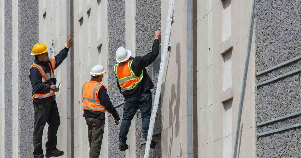
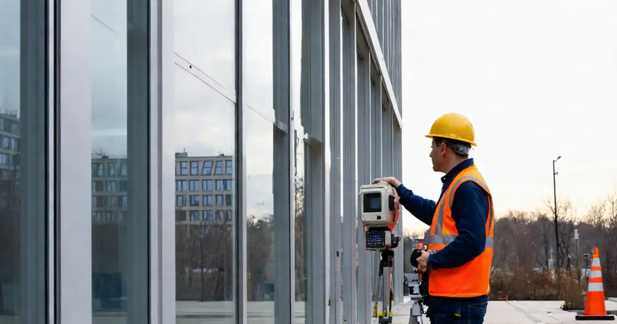
Provide a rigorous, sequence-accurate method and ITP for QA/QC hold and witness points governing facade alignment and tolerance verification, including: grid line survey, datum transfer, plumb and level checks, joint width consistency, planarity, as-built records, and final acceptance prior to sealant application.
Inclusions
- Unitised and stick curtain wall, rainscreen cladding, and mixed facade systems.
- Survey control verification and setting-out of facade gridlines.
- Progressive dimensional controls during installation.
- Pre-sealant Hold Point acceptance and release to sealant works.
- As-built survey and records submission.
Exclusions
- Structural design and analysis of facade systems.
- Structural anchor pull-out and water/air infiltration performance tests (covered under separate methods/ITPs).
Key Acceptance Themes
- Compliance with approved tolerances for position, plumb, level, joint width, and planarity.
- 100% checks at Hold Points; progressive checks as defined.
- All deviations rectified before pre-sealant release.
References
| Document Type | Reference / Number | Revision | Notes |
|---|---|---|---|
| Contract/Drawings | Project Specifications; Approved Shop Drawings | ||
| International Standard | ISO 4463-1 | For planning/organization of setting-out and dimensional control. | |
| International Standard | ISO 7976-1; ISO 7976-2 | ||
| British Standard (Guidance) | BS 5606 | ||
| International Standard | ISO 17123-3; ISO 17123-2; ISO 17123-8 | Instrument verification and field checks. | |
| Industry Standard (UK) | CWCT Standard for systemised building envelopes | Use where contract references CWCT. | |
| ASTM | ASTM C1193 | Pre-sealant joint dimensional checks. | |
| ASTM/ISO | ASTM C920; ISO 11600 | For minimum/maximum joint dimensions and movement capability. |
Responsibilities
| Role | Responsibility | Name / Party |
|---|---|---|
| PM | Contractor | Contractor |
| QA/QC Manager | Contractor | Contractor |
| Site Engineer | Contractor | Contractor |
| Supervisor | Contractor | Facade Subcontractor |
| Installers | Subcontractor | Facade Subcontractor |
| HSE | Contractor | Contractor |
| Surveyor | Specialist | Independent |
| Engineer | Engineer | Consultant |
| Calibration Lab | Accredited Lab | Accredited Provider |
Resources
| Resource Type | Description | Quantity | Remarks |
|---|---|---|---|
| Personnel | Lead surveyor for control and measurements. | 1–2 [Verify] | |
| Personnel | Checks, ITR completion, IR coordination. | 1–2 [Verify] | |
| Personnel | Adjustments and protection of works. | As required [Verify] | |
| Personnel | Access at height for checks/adjustments. | Certified, number per access plan [Verify] |
Materials
| Material | Specification / Grade | Quantity | Remarks |
|---|---|---|---|
| Targets/Prisms | Compatible with EDM/TS | As required | |
| HDPE/EPDM | Hardness 60–70 Shore A [Verify] | As required | |
| Low-tack tape | Residue-free removal | As required |
Equipment
| Equipment | Capacity / Type | Quantity | Inspection Required |
|---|---|---|---|
| Robotic TS preferred | 1–2 sets [Verify] | ||
| 1 set | |||
| As required | |||
| 2 | |||
| 2 sets | |||
| 2–4 | |||
| SWL per equipment | As per access plan | ||
| 1 each | |||
| As required |
Prerequisites
- Approved shop drawings and tolerance schedule available at point of work.
- Primary survey control points established and accepted by Engineer; coordinates disseminated to the survey team.
- Valid calibration certificates for TS, digital level, inclinometer, gauges; daily field checks logged.
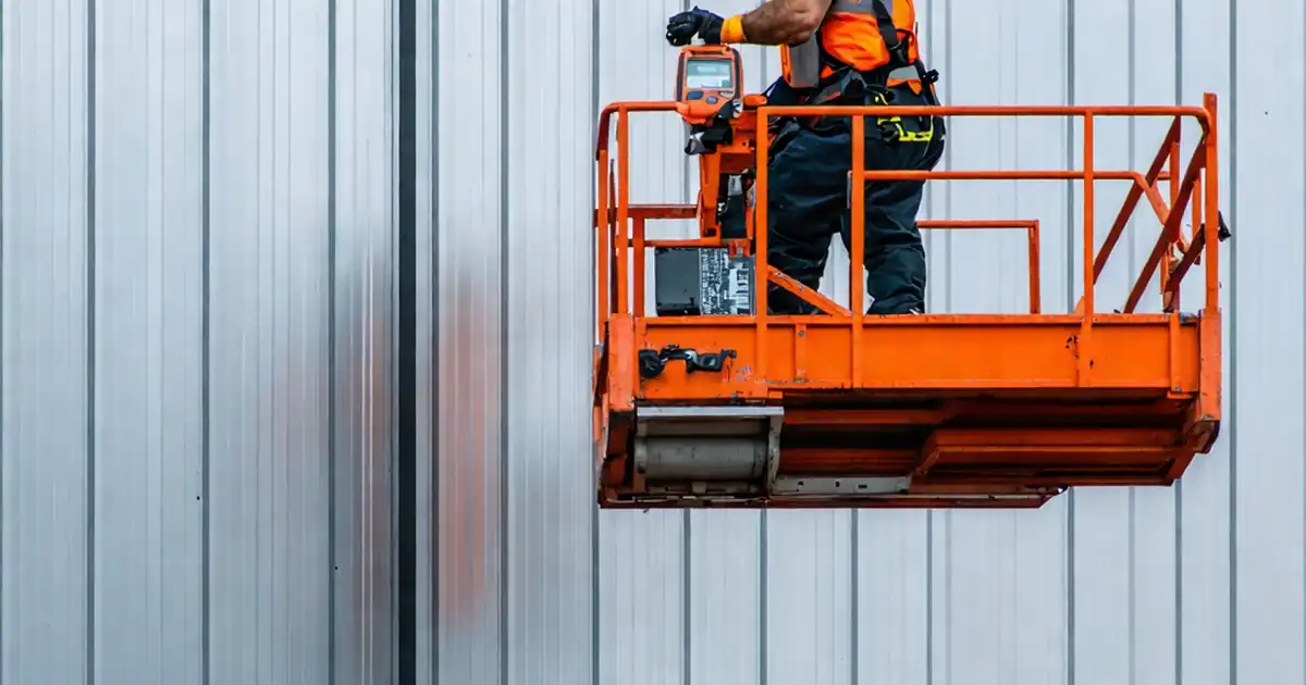
- Safe access in place (MEWP/scaffold), PTW issued where required, exclusion zones established.
- Facade brackets/rails installed to the stage enabling alignment checks; fixings tightened to specified torque [Verify].
- Weather suitable for reliable measurement; wind below MEWP limits; temperature within normal operating range for facade system [Verify].
- Surfaces clean for accurate contact of straightedge and gauges; protective films adjusted to expose measurement edges as needed.
- Gridline and level benchmarks transferred to working floors and protected from disturbance.
- Template ITRs, checklists, and IRs pre-filled with identification (zone, elevation, bay/panel numbers).
- Coordination with adjacent trades to avoid obstruction and to ensure joints are not compromised.
- Toolbox talk completed for survey/inspection team covering hazards and controls.
- Engineer notified of upcoming Hold/Witness Points per contract notice period.
- NCR/DR process ready for immediate use if deviations are found.
Method Sequence
| Step | Activity | Description | Responsibility | Inspection / Hold Point |
|---|---|---|---|---|
| 01 | Pre-Start Quality Briefing | Review approved drawings, tolerances, ITP hold/witness points, checklists, and survey method. Assign responsibilities and confirm access plan. | QA/QC Manager, Facade Supervisor | Internal |
| 02 | HP-01 HOLD POINT: Verification of Survey Control | Check primary control points using TS via closed traverse/tie to project control; confirm BM levels using double-run levelling. Protect points afterward. | Site Engineer; QA/QC; Engineer (review) | Engineer review |
| 03 | Setting-Out Facade Gridlines & Datums | Transfer approved gridlines and elevation datums to working floors; install survey targets at grid intersections and key facade points; mark on structure. | Site Engineer | Witness by QA/QC |
| 04 | Substrate/Bracket Line Verification | Verify bracket rails/receiver profiles relative to set-out lines prior to panel installation; check fixity and offsets enabling final alignment. | Facade Supervisor; QA/QC | Internal/Witness |
| 05 | WP: Progressive Panel Alignment During Installation | As each bay/panel is installed, set plumb/level and preliminary joint using spacers and adjustment hardware. Protect edges. | Installers; Facade Supervisor | Internal |
| 06 | HP-02 HOLD POINT: First-Of-Kind (FOK) Bay Check | Comprehensive alignment verification on the first completed representative bay/stack including plumb, level, joint width, planarity, offsets, and as-built spot coordinates. Agree benchmarks for production. | QA/QC; Engineer | Engineer hold |
| 07 | Production Alignment Checks by Grid/Bay | Repeat FOK checks at defined frequency: every bay for plumb/level/joint; planarity every second bay and all corners; increased frequency if NCRs occur. | QA/QC; Installers | Internal/Witness |
| 08 | Joint Width Consistency and Sealant Design Check | Verify joint width and depth against design; confirm minimum sealant bite and movement capability per product data before sealing. | QA/QC; Facade Engineer | Witness/Engineer review as required |
| 09 | As-Built Survey of Facade Lines | Capture coordinates of key facade points at grid intersections/corners and at defined intervals; compile as-built model/drawings and variance report. | Site Engineer | Engineer review (as required) |
| 10 | Defect Rectification and Re-Inspection | Where out-of-tolerance, adjust panels/rails or replace components; re-measure affected dimensions and update records/NCRs. | Facade Supervisor; QA/QC | Engineer witness for NCR closure |
| 11 | HP-03 HOLD POINT: Pre-Sealant Acceptance | Final verification of alignment, plumb, level, joint width, planarity, cleanliness, and record completeness prior to authorising sealant works. | QA/QC Manager; Engineer | Engineer hold |
| 12 | Release to Sealant Applicators | Issue formal release; brief applicators on joint dimensions; reconfirm no movement/adjustment will occur post-release. | QA/QC; Facade Supervisor | Internal |
Safety Controls
Task-Specific Hazards and Controls
1) Hazard: Work at height from MEWP/scaffold near facade edges
- Likely consequence: Falls from height causing serious injury/fatality
- Engineering/procedural control: Engineered access (certified MEWP/scaffold), edge protection, anchor points; pre-use inspection and tagged; MEWP operated per lift plan; maintain exclusion zone below
- Required PPE: Full-body harness with lanyard for MEWP, hard hat with chin strap, safety footwear, cut-resistant gloves, eye protection
- Collective preventive measure: Guardrails/toeboards on platforms; fall arrest systems; barricades and signage
- Inspection/permit/supervision: PTW for work at height; daily MEWP/scaffold inspection log; competent operator and supervisor; weather check for wind limits [Verify per project HSE plan and local regulations]
2) Hazard: Falling objects during measurement/adjustment
- Likely consequence: Struck-by injury to persons below; facade/glass damage
- Engineering/procedural control: Tool lanyards; secure small parts in pouches; exclusion zone beneath work area; debris nets where required
- Required PPE: Hard hat, safety footwear, eye protection
- Collective preventive measure: Physical barriers and spotters controlling access below
- Inspection/permit/supervision: Daily inspection of lanyards/attachments; supervisor to enforce exclusion zones
3) Hazard: Glass/metal sharp edges during joint gauge use
- Likely consequence: Lacerations to hands/forearms
- Engineering/procedural control: Use cut-resistant gloves; avoid sliding hands along edges; maintain protective films where possible
- Required PPE: Cut-resistant gloves (EN 388 level per risk), long sleeves, safety glasses
- Collective preventive measure: Briefing on safe handling; dedicated handling points
- Inspection/permit/supervision: Supervisor checks PPE compliance; first-aid kit available nearby
4) Hazard: Laser exposure from TS/laser level
- Likely consequence: Eye irritation/injury
- Engineering/procedural control: Use Class 2/3R lasers only; avoid beam at eye level; post laser-in-use signs
- Required PPE: Eye protection as needed
- Collective preventive measure: Controlled survey line-of-sight; restrict bystanders
- Inspection/permit/supervision: Verify laser class; operator training; equipment calibration records
5) Hazard: Pinch/crush during panel adjustment
- Likely consequence: Hand/finger injuries; musculoskeletal strain
- Engineering/procedural control: Use designed adjustment points and tools; no hands in pinch zones; team communication and spotter
- Required PPE: Impact/cut-resistant gloves; safety boots
- Collective preventive measure: Method briefing; lock-out of lifting equipment not in use
- Inspection/permit/supervision: Supervisor oversight during adjustments; stop-work authority if unsafe
6) Hazard: Weather (high winds, heat)
- Likely consequence: Loss of control of access equipment; measurement errors; heat stress
- Engineering/procedural control: Suspend works above equipment wind limits; schedule checks in stable conditions; hydration and rest breaks
- Required PPE: Weather-appropriate PPE; sunscreen where applicable
- Collective preventive measure: Shade/water stations
- Inspection/permit/supervision: Monitor wind speed/temperature; supervisor to pause works if limits exceeded
7) Hazard: Manual handling of straightedges and equipment at heights
- Likely consequence: Strains, dropped objects
- Engineering/procedural control: Use tether points for long straightedges; team lifts; store equipment securely on platform
- Required PPE: Gloves, safety footwear
- Collective preventive measure: Equipment racks on platforms
- Inspection/permit/supervision: Pre-use checks; supervisor verification
Note: Apply further controls required by the project HSE plan and local regulations.
Environmental Controls
- Protect facade surfaces from staining or adhesive residue; use non-staining tapes and remove promptly after checks.
- Prevent debris from falling to public/landscaped areas; use debris nets/exclusion zones and clean-down at end of shift.
- Manage MEWP emissions/noise per site rules; avoid idling; schedule noisy activities within permitted hours [Verify per local regulations].
- Collect and segregate packaging waste from targets/spacers; dispose via designated recycling streams.
- Do not discharge wash water or cleaning solvents to drains; if cleaning is required for accurate measurement, use approved products and capture waste [Verify per project EMP].
- Avoid measurements during direct facade heating that may cause thermal bow; record ambient temperature and wind to contextualize as-built data.
- Protect biodiversity and adjacent properties by preventing object drop and dust; maintain housekeeping standards.
QA/QC
Measurement Methods
- Position: Total Station set-out and independent check-back per ISO 4463-1. Use resection/backsight checks; apply least-squares adjustment where appropriate.
- Level: Digital level double-run; close levelling loops; record misclosures.
- Plumb: Digital inclinometer on mullions; cross-check with plumb laser over representative height.
- Levelness: Laser/digital level on transoms.
- Joint width: Calipers or joint gauges at top/mid/bottom of each joint; record min/avg/max.
- Planarity: 2 m straightedge with feeler gauges across panel seams and within panel fields.
Sampling and Frequency [Verify per project]
- 100% of bays for plumb, level, and joint width prior to pre-sealant Hold Point.
- Planarity: 100% of corners/returns; every second bay on runs; increase to 100% upon any NCR.
- As-built: All gridline intersections and corners; every 2 bays along long elevations; denser grid where deviations noted.
Typical Acceptance Criteria [Verify per project specifications]
- Gridline position: ≤±3 mm local to design.
- Level transfer: ≤±2 mm between adjacent bays; ≤±5 mm over 30 m runs.
- Plumbness: ≤2 mm/m; max 6 mm per storey; cumulative deviation ≤10 mm over multi-storey stack.
- Joint width: As per drawing (typ. 10–20 mm) within ±2 mm; minimum width to satisfy sealant movement capability (e.g., w ≥ 2×expected movement; typical min ≥6 mm).
- Panel-to-panel offset: ≤2 mm at abutting edges.
- Planarity: Gap under 2 m straightedge ≤3 mm.
Records and Traceability
- ITR checklists for each bay/zone with unique IDs matching drawings.
- IR approvals for all Hold/Witness Points.
- Survey reports (CSV, DWG/PDF), photos with tags, calibration certificates.
- NCR/DR forms for all deviations, with corrective actions and closure evidence.
Nonconformance Management
- Immediate notification to QA/QC and Engineer for any out-of-tolerance findings at Hold Points.
- Stop progression to sealant works in affected zones until rectified and re-inspected.
Document Control
- All records uploaded to CDE within 24 hours; filenames to include date, zone, elevation, bay/panel IDs.
- Revisions tracked; superseded documents archived per project QA plan.
Attachments
- Sample ITRs: Control Verification; Grid Set-Out; Bracket Line; FOK Bay; Production Alignment; Joint Width; Pre-Sealant Release.
- Example checklists for plumb, level, joint width, and planarity.
- IR template with Hold/Witness classification.
- Survey control/calibration certificate templates.
- As-built deliverable template: CSV point list, coordinate system definition, DWG title block.
- NCR/DR and Concession request templates.
- Access plan and PTW forms for MEWP/scaffold.
- Manufacturer data: sealant movement capability; joint design guides.
- Copy of approved tolerance schedule from project specifications.
This content is a read-only public reference. Download or customize to get an editable version.
ITP preview
The first inspection activities from the linked ITP for Method Statement: QA/QC Hold Points for Facade Alignment and Tolerance Verification:
| Activity | Inspection / Test | Acceptance Criteria | Responsibility | Record |
|---|---|---|---|---|
| HP-01 HOLD POINT: Verification of Survey Control | Traverse/level checks; calibration verification | Control position ≤±3 mm; level misclosure within method limits; instruments validated [Verify] | Site Engineer (Contractor) / QA/QC / Engineer (Approval) | Survey control report; IR approval; calibration certs |
| Setting-Out of Facade Gridlines & Datums (Witness) | TS set-out and check-back | Grid/datum within specified tolerances [Verify] | Site Engineer / QA/QC (Witness) | Set-out report; marked drawings; photos |
| Bracket/Rail Line Verification (Witness) | Tape/TS spot checks; straightedge | Line within ±3 mm; planarity ≤3 mm over 2 m; torque per spec [Verify] | Facade Supervisor / QA/QC (Witness) | Bracket checklist; torque records; photos |
Showing 3 of 9 inspection activities. View full ITP →
Related Inspection and Test Plan
An Inspection and Test Plan (ITP) is available for Method Statement: QA/QC Hold Points for Facade Alignment and Tolerance Verification. The ITP defines the inspection activities, acceptance criteria, hold and witness points, responsible parties, and records required to verify the work described in this method statement.
View the Method Statement: QA/QC Hold Points for Facade Alignment and Tolerance Verification ITP →Frequently asked questions
Continue with related Quollnet resources connected to this method statement.