
Method Statement: Joint Sealing of Precast Concrete Panels (Horizontal & Vertical), Backer Rod Installation, Sealant Application, and Field Adhesion Pull-Off Testing – Method Statement
AI-assisted method statement with matching ITP, PDF download, and Excel export.
More than a static template
Unlike a downloadable Word or PDF template, this method statement is an AI-assisted editable starting point connected directly to a matching Inspection and Test Plan. Every section is structured, project-adaptable, and ready to export.
- AI-assisted drafting — Customize every section with AI for your specific project scope.
- Linked ITP — A matching inspection and test plan is generated alongside the method statement.
- Multiple export formats — Download as a formatted PDF or editable Excel spreadsheet.
- Editable starting point, not a final document — Review, verify, and adjust all content against your project requirements before use.
Static template vs. Quollnet workflow
| Feature | Static template | Quollnet |
|---|---|---|
| Project-specific content | Manual fill-in required | AI-assisted customization |
| Linked ITP | Separate document, no link | Matching ITP included |
| Export formats | Usually PDF only | PDF and Excel |
| Structured sections | Free-form layout | 13 standardized sections |
| Saved to your account | Local file only | Cloud-saved, reusable |
| Content accuracy | You verify everything | AI-assisted, you still verify |
| Cost | Often free but time-intensive | Free to customize and download |
What you can customize
When you save this method statement to your account, every section becomes editable. The following 13 sections are included:
- Scope — Defines the activity and its boundaries.
- References — Standards, specifications, and drawings.
- Responsibilities — Roles and accountabilities.
- Resources — Labour, plant, and equipment summary.
- Materials — Materials and compliance requirements.
- Equipment — Tools and equipment details.
- Prerequisites — Hold points and pre-conditions.
- Method sequence — Step-by-step construction sequence.
- Safety controls — HSE risk controls and PPE.
- Environmental controls — Environmental mitigation measures.
- QA/QC — Quality inspection and test requirements.
- ITP — Inspection and Test Plan table (has its own page).
- Attachments — Referenced drawings and documentation.
Why this method statement is used
This method statement is used to define and communicate the approved procedure for carrying out method statement: joint sealing of precast concrete panels (horizontal & vertical), backer rod installation, sealant application, and field adhesion pull-off testing on site. It ensures the work is planned in advance, the correct resources and controls are in place, and all personnel understand responsibilities, sequence, quality requirements, and safety controls before work begins. It aligns site execution with the documented scope and acceptance expectations.
Who uses this method statement
This method statement is used by contractors, site supervisors, project engineers, QA/QC engineers, HSE officers, consultants, and client representatives. It serves as a shared reference for planning, execution, supervision, inspection, and approval of the activity on site.
When it is prepared and submitted
The method statement is prepared before the work activity starts and submitted as part of the pre-construction documentation package for review and approval.
Who reviews or approves it
The method statement is usually submitted to the client representative, consultant, resident engineer, or project management consultant for review and approval before the work commences.
Important approval note
This method statement is an AI-assisted editable starting point, not a pre-approved document. Before use on any project, all content must be reviewed and approved by the relevant parties (superintendent, principal contractor, or client representative) in accordance with your contract and project quality plan.
For example: if your specification requires a departure from a referenced standard, that departure must be documented and approved separately — this method statement will not capture that automatically. Always verify against your applicable drawings, specifications, and regulatory requirements.
Method statement content
Scope
Work Summary
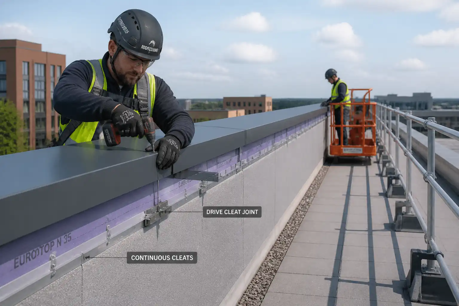
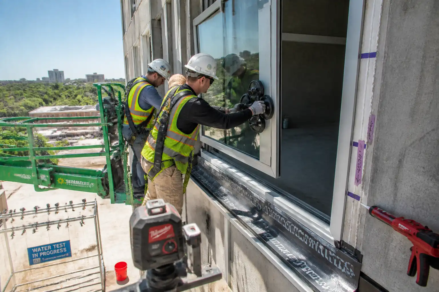
- Preparation and sealing of horizontal and vertical movement/weather joints between precast concrete panels, including removal of defective existing sealant where present, surface preparation, installation of compressible backer rod, primer (if required), application and tooling of elastomeric sealant, curing protection, and field adhesion pull-off tests.
Inclusions
- Pre-start mock-up and approval.
- Verification of joint design dimensions and movement requirements.
- Cleaning, grinding/abrading arrises as needed, dust control, and masking.
- Supply and installation of backer rod and bond breaker tape to prevent three-sided adhesion.
- Application of one-part or multi-part low-modulus façade grade sealant (silicone/STPE/PU) per approved data sheets.
- Tooling to specified profile, finish quality control, and protection until cured.
- Field adhesion testing per ASTM C1521, documentation, and any corrective works.
Exclusions [Verify per contract]
- Structural grouting of panel joints.
- Firestopping, acoustic, or submerged joints (separate method required).
- Panel erection/alignment works.
Typical Joint Design Benchmarks [Verify per project specifications]
- Joint width: 10–25 mm typical (façade); movement capability selected to suit design movement (e.g., ±25% or ±50%).
- Sealant depth: for widths ≤25 mm, depth ≈ half the width, minimum 6 mm; maximum 12 mm unless manufacturer states otherwise.
- Backer rod diameter: 25–50% larger than joint width to achieve proper compression without tearing.
- Finished profile: tooled concave, slight recess (0–2 mm) from arris; smooth, free of voids and pinholes.
References
| Document Type | Reference / Number | Revision | Notes |
|---|---|---|---|
| Standard | ASTM C1193 – Guide for Use of Joint Sealants | General design, surface preparation, application, and inspection guidance for sealants. | |
| Standard | ASTM C920 – Specification for Elastomeric Joint Sealants | Performance requirements and classification of sealants (Type, Grade, Class). | |
| Standard | ISO 11600 – Building construction sealants – Classification and requirements | International classification; e.g., F-25LM for façade low-modulus class 25. | |
| Standard | BS EN 15651-1 – Sealants for façade elements | European product standard for façade sealants. | |
| Standard | ASTM C1521 – Field Adhesion Testing of Installed Weatherproofing Sealant Joints | Defines hand-pull (Method A) and instrumented (Method B) field adhesion tests. | |
| Standard | ASTM C1330 – Cylindrical Sealant Backing for Use with Cold Liquid Applied Sealants | Requirements for closed-cell and bi-cellular polyethylene backer rods. | |
| Standard | ASTM D4258 – Standard Practice for Surface Cleaning Concrete for Coating | Applicable guidance for cleaning concrete substrates prior to sealing. | |
| Guideline | ICRI 310.2R – Guide to Selecting and Specifying Concrete Surface Preparation | Select light abrasive/Grinding profile where required for sound substrate. | |
| Manufacturer | Approved Sealant & Primer Manufacturer Data Sheets (PDS/SDS) | Mixing, application, primer use, open time, tooling, cure, compatibility. | |
| Contract | Project Specifications and Drawings | Joint geometry, movement requirements, colors, approvals, and submittals. |
Responsibilities
| Role | Responsibility | Name / Party |
|---|---|---|
| PM | Approvals, programme, change control. | Contractor |
| Engineer | Daily checks, RFI/ITP coordination. | Contractor |
| QA/QC | ITP compliance, inspection records, NCR/CAR management. | Contractor |
| HSE | HSE compliance and monitoring. | Contractor |
| Foreman | Workmanship, productivity, QA at source. | Subcontractor |
| Operator | Pre-use checks, safe positioning. | Subcontractor |
| Independent | Issue test certificates. | Laboratory/Consultant |
Resources
| Resource Type | Description | Quantity | Remarks |
|---|---|---|---|
| Labor | Trained workers experienced in façade sealant systems. | 1 crew = 1 supervisor + 2–4 applicators [Adjust per workload] | |
| Labor | Dedicated quality control for checks and tests. | 1 per active elevation/area | |
| Labor | Scaffolders/MEWP operators for safe access and edge protection. | As required by access plan |
Materials
| Material | Specification / Grade | Quantity | Remarks |
|---|---|---|---|
| Elastomeric Sealant (Silicone/STPE/PU) | Comply with ASTM C920 and ISO 11600 [Verify per project specifications] | As per BOQ | |
| Backer Rod | ASTM C1330 Type B; diameter 25–50% greater than joint width | Joint length + 5% waste | |
| Primer | Manufacturer’s approved primer for substrate/sealant combination | As required by substrate | |
| Bond Breaker Tape | Non-adhesive PTFE/PE tape, compatible with sealant | As needed | |
| Cleaner/Solvent | Per sealant manufacturer SDS/PDS [Verify per project HSE plan] | As needed | |
| Masking Tape | Low-tack, non-staining, UV-resistant | As needed |
Equipment
| Equipment | Capacity / Type | Quantity | Inspection Required |
|---|---|---|---|
| Sealant Application Guns | Compatible with sealant packaging | ||
| Angle Grinder with Diamond Wheel + HEPA Vacuum | 125–150 mm wheel | ||
| Oil-free Air Compressor + Blow-out Nozzles | 0.5–1.0 m³/min @ 6–8 bar | ||
| MEWP/Scaffold/Ladders | SWL per manufacturer; scaffold tagged "Safe to Use" | ||
| Field Adhesion Test Kit | Spring scale 0–200 N, cutting tools, ruler, timer | ||
| Thermo-hygrometer/IR Thermometer | Accuracy ±0.5°C / ±3% RH | ||
| Feeler Gauges/Calipers/Depth Gauge | 0–50 mm range |
Prerequisites
Administrative
- Approved shop drawings and joint schedules indicating target joint widths, movement class, color, and sealant type. [Verify per project specifications]
- Approved material submittals: sealant, primer, backer rod, bond breaker tape; SDS on site.
- Approved method statement and ITP; completed risk assessment and toolbox talk specific to joint sealing and access.
- Permits: Working at Height/MEWP permit; Hot Work permit if grinding is classified as hot work. [Verify per project HSE plan and local regulations]
Site Conditions
- Surfaces sound, dry, clean, and frost-free; no active water ingress. Concrete age per manufacturer recommendations or moisture content acceptable for sealant bonding (no visible moisture film). [Verify per project specifications]
- Ambient and substrate temperatures typically 5–40°C; substrate at least 3°C above dew point; wind and rain protection arranged. [Verify per manufacturer]
- Access/scaffolding installed, inspected (green-tagged), and edge protection in place.
- Mock-up location agreed and scheduled for early approval.
Materials & Equipment
- Materials within shelf life; stored at 10–27°C away from heat/sun; batch numbers recorded.
- Calibration/verification current for measuring devices and field adhesion kit.
- Adequate masking materials, clean lint-free cloths, approved solvent, and compatible primers available.
Interface Checks
- Adjacent finishes protected; drainage paths not obstructed.
- Compatibility verified with adjacent substrates and any previous sealants/cleaners (conduct compatibility test if required by manufacturer).
Method Sequence
| Step | Activity | Description | Responsibility | Inspection / Hold Point |
|---|---|---|---|---|
| 1 | Pre-Start Briefing & Permits | Conduct task-specific toolbox talk covering access, solvents, dust, and testing. Obtain PTW for MEWP/Working at Height and Hot Work if grinding. | HSE Officer / Supervisor | Permit check |
| 2 | Mock-Up | Prepare 2–3 m of representative joint (horizontal and vertical if applicable). Include all steps: cleaning, backer rod, primer, sealant, tooling. Allow to cure and perform field adhesion test. | Site Engineer / QA/QC | Engineer/Client review |
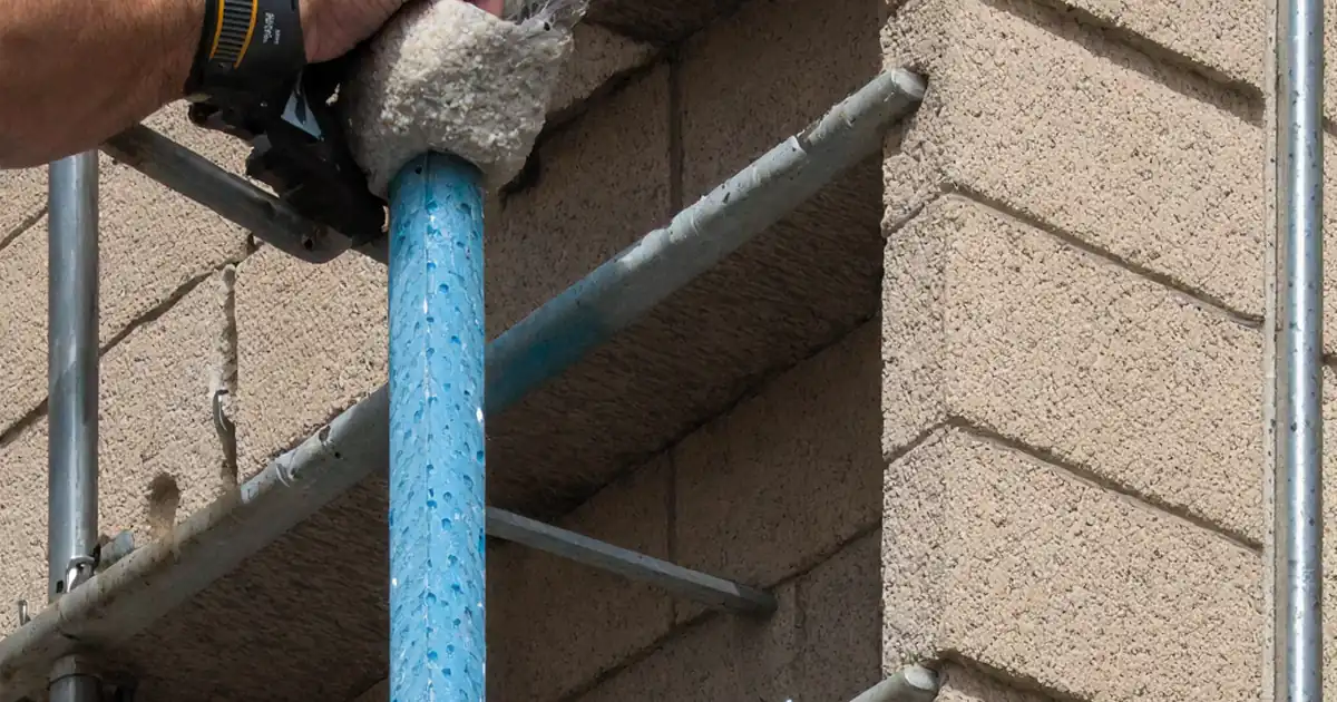
| 3 | Removal of Existing Sealant (if any) | Cut out existing sealant fully using knives/scrapers; avoid damaging arrises. Remove residuals by mechanical means (light grinding) and solvent wipe per manufacturer (two-cloth method). Collect waste for proper disposal. | Sealant Crew | Visual |
| 4 | Surface Preparation | Brush/vacuum loose debris; grind/abrade laitance or weak surfaces to sound concrete (ICRI CSP 1–2). Blow out with oil-free air. Final solvent wipe with lint-free cloth where required. Mask edges neatly. | Sealant Crew | Visual + touch clean |
| 5 | Verify Joint Geometry | Measure joint width and depth at 2 m intervals minimum or every joint segment; record ambient/surface temperature and dew point. | QA/QC | Measurement |
| 6 | Install Backer Rod / Bond Breaker | Select rod diameter 25–50% larger than joint width. Insert continuously without twisting to target depth using blunt tool; do not puncture skin. Where depth insufficient, install non-adhesive bond breaker tape on joint base. | Sealant Crew | Visual + depth spot checks |
| 7 | Primer Application (if required) | Apply approved primer to joint flanks only with small brush/dauber per PDS. Observe coverage and open time. Prevent pooling on backer rod or joint base. | Sealant Crew | Visual |
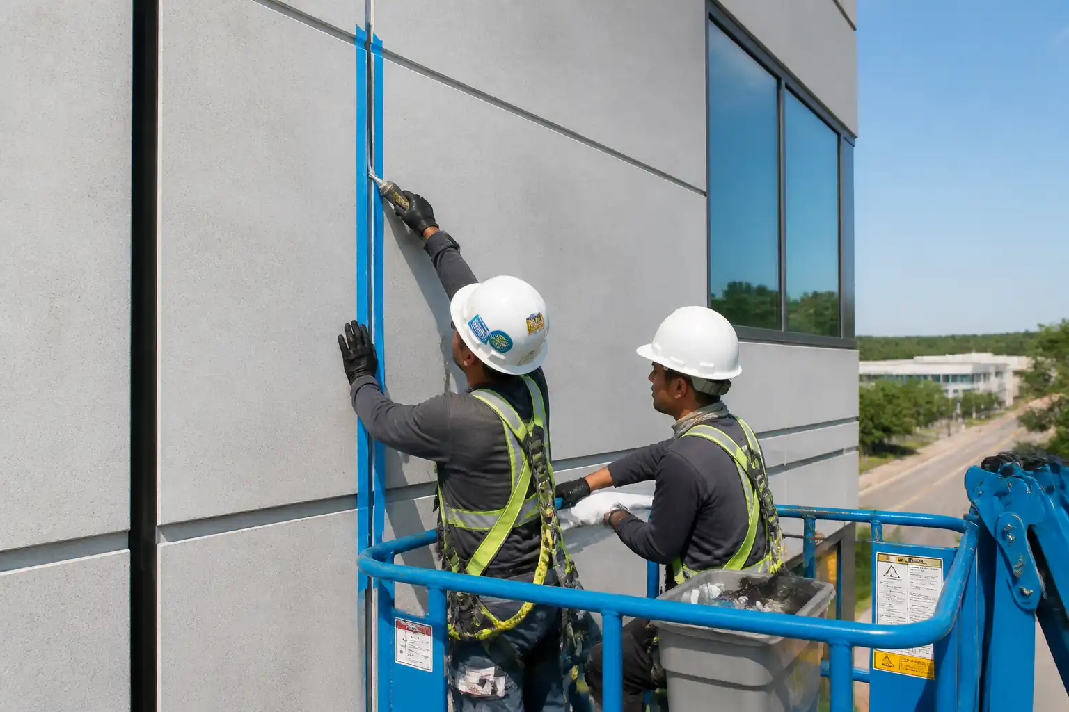
| 8 | Sealant Application | Load gun; purge first 50–100 ml to waste. Gun sealant from one end, maintaining nozzle below bead surface to avoid entrapped air; fill from deepest point, continuous passes. Maintain bead slightly proud for tooling. | Sealant Applicator | In-process observation |
| 9 | Tooling and Finishing | Tool within manufacturer’s tooling time using suitable spatula lightly wetted with approved tooling fluid (if allowed). Form concave profile; remove masking immediately after tooling without smearing. | Sealant Applicator | Visual |
| 10 | Curing & Protection | Protect from rain, dust, and mechanical damage until skin forms and through-cure achieved. Maintain environmental limits; prevent traffic/load on fresh joints. | Supervisor | Daily check |
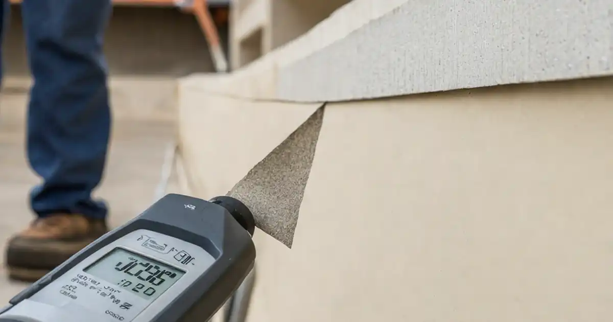
| 11 | Field Adhesion Test (ASTM C1521) | After reaching manufacturer’s minimum cure for testing, cut a 75 mm long by full-depth tab and perform Method A hand-pull at 180° using spring scale; record peak force and mode of failure. Frequency: ≥1 test per 75 m of joint per substrate/sealant lot and per elevation, minimum 3 tests per day per crew. [Verify per project]. | QA/QC | Witness by Engineer (if required) |
| 12 | Defect Rectification | Where adhesion/finish is nonconforming: remove affected length plus 150–300 mm beyond defect; re-prepare and reseal; re-test after cure. | Supervisor / QA/QC | Follow-up inspection |
| 13 | Final Inspection & Handover | Comprehensive walkdown: bead continuity, color, neatness, no staining. Submit as-builts, warranties, O&M, and test records. | Site Engineer / QA/QC | Engineer/Client punchlist |
Safety Controls
Task-Specific Hazards and Controls
1) Working at Height (MEWP/Scaffold)
- Hazard: Fall from height; MEWP tip-over; falling objects.
- Consequence: Severe injury/fatality.
- Engineering/Procedural Controls: Certified MEWP operators; pre-use inspection and daily MEWP checklist; ground assessment (level/firm); fall protection anchor points; scaffold erected/inspected by competent personnel and tagged; exclude zone with toe boards and debris nets; tool lanyards; maintain 3:1 safe setback from edges if mobile tower used; do not overreach.
- PPE: Full-body harness with short lanyard for MEWP, helmet with chin strap, gloves, safety boots, eye protection.
- Collective Measures: Guardrails on scaffold; MEWP guardrails; exclusion zones below.
- Inspection/Permit/Supervision: Working at Height permit; MEWP inspection certificate current; weekly scaffold inspection tags; supervisor present. [Verify per project HSE plan and local regulations]
2) Solvent/Primer and Sealant Chemicals (isocyanates/solvents)
- Hazard: Inhalation/dermal exposure; fire risk.
- Consequence: Respiratory/skin sensitization, eye irritation, fire.
- Controls: Use low-VOC/non-isocyanate where possible; work in well-ventilated areas; closed containers; no ignition sources; follow two-cloth cleaning method; decant minimal quantities; spill kit available.
- PPE: Nitrile gloves, safety goggles/face shield for splashes, long sleeves; half-mask respirator with organic vapor cartridges if required by SDS.
- Collective Measures: No-smoking zone; fire extinguisher (CO2/foam) nearby; ventilation fans if enclosed.
- Inspection/Permit/Supervision: SDS on site; chemical register; Hot Work permit if ignition sources present; HSE supervision for compliance.
3) Grinding/Abrasion and Dust
- Hazard: Silica dust, flying debris, noise, sparks.
- Consequence: Respiratory disease, eye injury, hearing loss, fire if near combustibles.
- Controls: HEPA local extraction on grinders; wet suppression where feasible but avoid wet joint prior to sealing; position spark shields; segregate area.
- PPE: FFP3/N95 respirator (per local standard), safety goggles, hearing protection, cut-resistant gloves.
- Collective Measures: Physical barriers and signage; scheduled noisy works at permitted hours.
- Inspection/Permit/Supervision: Hot Work permit if classified; equipment PAT/inspection; noise monitoring if required.
4) Manual Handling and Repetitive Strain
- Hazard: Lifting MEWP components/material boxes; repetitive tooling motions.
- Consequence: Musculoskeletal injuries.
- Controls: Use mechanical aids; team lifts; rotate tasks; ergonomic tools and correct stance.
- PPE: Gloves with grip; supportive footwear.
- Collective Measures: Material hoists; staging close to work face.
- Inspection/Permit/Supervision: Supervisor to plan lifts; manual handling training records.
5) Weather and Surface Condition
- Hazard: Wet or icy surfaces affecting adhesion and access safety; wind affecting MEWP stability.
- Consequence: Slips/falls; poor bonding.
- Controls: Stop work during rain or high winds beyond MEWP limits; confirm substrate temp ≥3°C above dew point; use temporary weather protection/screening.
- PPE: Weather-appropriate clothing, anti-slip footwear.
- Collective Measures: Windbreaks, temporary canopies.
- Inspection/Permit/Supervision: Daily weather check documented; supervisor authorization to proceed.
6) Sharp Tools/Cutting
- Hazard: Lacerations from knives/scrapers during removal of old sealant.
- Consequence: Cuts; infection.
- Controls: Use sharp retractable knives; cut away from body; provide cut-resistant gloves; dispose blades in sharps container.
- PPE: Cut-resistant gloves, eye protection.
- Collective Measures: Designated cutting area for prep; blade dispensers.
- Inspection/Permit/Supervision: Toolbox briefing; spot checks by HSE.
7) Contact with Fresh Sealant on Skin/Eyes
- Hazard: Irritation/sensitization.
- Consequence: Dermatitis, eye injury.
- Controls: Avoid solvent-contaminated rags on skin; immediate wash stations/eyewash; prohibit solvent hand-cleaning; provide citrus-based hand cleansers.
- PPE: Nitrile gloves, goggles.
- Collective Measures: Eyewash within 10 m; hygiene facilities.
- Inspection/Permit/Supervision: First-aid availability; HSE inspections.
Environmental Controls
Controls for Environmental Impacts
- VOC Emissions: Select low-VOC products where feasible; keep containers closed; minimize solvent use; maintain SDS and ensure ventilation.
- Dust and Noise: Use HEPA extraction; schedule grinding during permitted hours; monitor noise if required; use acoustic screens near sensitive receptors.
- Waste Management: Collect spent cartridges, backer rod offcuts, masking, and solvent-contaminated rags in labeled containers; dispose via licensed waste contractor; segregate hazardous waste per SDS.
- Spill Prevention: Secondary containment for primers/solvents; spill kits at point-of-use; train crew in spill response; prevent discharge to drains.
- Weather Protection and Runoff: Use drip trays and poly sheeting to protect below; avoid sealing immediately before rain; prevent wash-off staining.
- Material Storage: Store under cover on spill pallets; avoid prolonged heat/sun exposure to prevent product degradation.
- Wildlife/Vegetation: Prevent overspray/solvent drift to landscaping; erect barriers where required.
- Compliance: Follow project EMP and local environmental regulations; keep disposal receipts and waste transfer notes for audit.
Quality Assurance / Quality Control
Submittals & Approvals
- Product Data: Sealant (type/class), primer, backer rod, bond breaker, cleaners; SDS; color charts; evidence of compliance with ASTM C920/ISO 11600/EN 15651.
- Compatibility/Mock-Up: Submit mock-up for approval; conduct any required stain testing on representative substrates.
Material Control
- Verify shelf life, batch numbers, storage conditions (10–27°C), and unopened packaging at delivery.
- Maintain batch traceability to installed locations.
Execution Controls
- Environmental limits recorded each shift: ambient and substrate temperature, RH, dew point.
- Joint dimension checks at minimum every 2 m; record backer rod size and depth.
- Primer application: record lot, start/finish time, and open time compliance.
- Sealant mixing (if multi-part): record mix ratio by weight/volume, induction time, pot life.
- Finish criteria: concave profile, uniform width, clean arrises, recess 0–2 mm, no pinholes/voids; color consistent.
Testing
- Field Adhesion: ASTM C1521 Method A as default; Method B if specified. Frequency: ≥1 per 75 m per substrate/lot/elevation; minimum 3 per day per crew. [Verify per project]
- Acceptance: Predominantly cohesive failure; adhesive failure ≤10%; equivalent adhesion ≥25 psi or per manufacturer recommendation; no edge debond. [Verify per project]
- Remedial Works: Remove and reseal defective stretches plus 150–300 mm beyond, re-test.
Documentation & Handover
- Maintain ITP checklists, field adhesion test reports (photos of cuts, pull, and failure mode), calibration certificates, daily QC logs, and as-built location plans.
- Provide manufacturer warranty and maintenance instructions.
Attachments
- Manufacturer Product Data Sheets (PDS) and Safety Data Sheets (SDS) for sealant, primer, cleaners.
- Mock-up approval record with photographs.
- Sample field adhesion test report template (ASTM C1521) with photo log.
- Joint detail sketches: typical vertical/horizontal joints; backer rod depth; bond breaker locations.
- Daily QC checklist (joint geometry, environmental readings, primer lot/open time, bead profile).
- Equipment pre-use inspection checklists (MEWP, grinder, compressor).
- Waste management plan extract for chemical/solvent waste.
- Training/competency records for applicators and MEWP operators.
This content is a read-only public reference. Download or customize to get an editable version.
ITP preview
The first inspection activities from the linked ITP for Method Statement: Joint Sealing of Precast Concrete Panels (Horizontal & Vertical), Backer Rod Installation, Sealant Application, and Field Adhesion Pull-Off Testing:
| Activity | Inspection / Test | Acceptance Criteria | Responsibility | Record |
|---|---|---|---|---|
| Materials Delivery Verification | Check compliance with ASTM C920/ISO 11600, shelf life, batch numbers, SDS | Approved submittals; within shelf life; intact packaging | QA/QC Engineer | Material inspection report |
| Mock-Up Preparation and Review | Construct mock-up; visual inspection; ASTM C1521 field adhesion | Engineer/Client approval; acceptable adhesion and finish | Site Engineer / QA/QC / Engineer | Mock-up approval form/photos |
| Substrate Condition & Geometry | Cleanliness check; measure joint width/depth; environmental readings | Sound, clean, dry; width within ±3 mm of design; depth adequate; dew point margin ≥3°C | QA/QC Engineer | Inspection checklist; readings log |
Showing 3 of 10 inspection activities. View full ITP →
Related Inspection and Test Plan
An Inspection and Test Plan (ITP) is available for Method Statement: Joint Sealing of Precast Concrete Panels (Horizontal & Vertical), Backer Rod Installation, Sealant Application, and Field Adhesion Pull-Off Testing. The ITP defines the inspection activities, acceptance criteria, hold and witness points, responsible parties, and records required to verify the work described in this method statement.
View the Method Statement: Joint Sealing of Precast Concrete Panels (Horizontal & Vertical), Backer Rod Installation, Sealant Application, and Field Adhesion Pull-Off Testing ITP →Frequently asked questions
Continue with related Quollnet resources connected to this method statement.