Method Statement: Mobile Crane Positioning, Outrigger Mat Configuration, and Ground Bearing Verification – Method Statement
AI-assisted method statement with matching ITP, PDF download, and Excel export.
More than a static template
Unlike a downloadable Word or PDF template, this method statement is an AI-assisted editable starting point connected directly to a matching Inspection and Test Plan. Every section is structured, project-adaptable, and ready to export.
- AI-assisted drafting — Customize every section with AI for your specific project scope.
- Linked ITP — A matching inspection and test plan is generated alongside the method statement.
- Multiple export formats — Download as a formatted PDF or editable Excel spreadsheet.
- Editable starting point, not a final document — Review, verify, and adjust all content against your project requirements before use.
Static template vs. Quollnet workflow
| Feature | Static template | Quollnet |
|---|---|---|
| Project-specific content | Manual fill-in required | AI-assisted customization |
| Linked ITP | Separate document, no link | Matching ITP included |
| Export formats | Usually PDF only | PDF and Excel |
| Structured sections | Free-form layout | 13 standardized sections |
| Saved to your account | Local file only | Cloud-saved, reusable |
| Content accuracy | You verify everything | AI-assisted, you still verify |
| Cost | Often free but time-intensive | Free to customize and download |
What you can customize
When you save this method statement to your account, every section becomes editable. The following 13 sections are included:
- Scope — Defines the activity and its boundaries.
- References — Standards, specifications, and drawings.
- Responsibilities — Roles and accountabilities.
- Resources — Labour, plant, and equipment summary.
- Materials — Materials and compliance requirements.
- Equipment — Tools and equipment details.
- Prerequisites — Hold points and pre-conditions.
- Method sequence — Step-by-step construction sequence.
- Safety controls — HSE risk controls and PPE.
- Environmental controls — Environmental mitigation measures.
- QA/QC — Quality inspection and test requirements.
- ITP — Inspection and Test Plan table (has its own page).
- Attachments — Referenced drawings and documentation.
Why this method statement is used
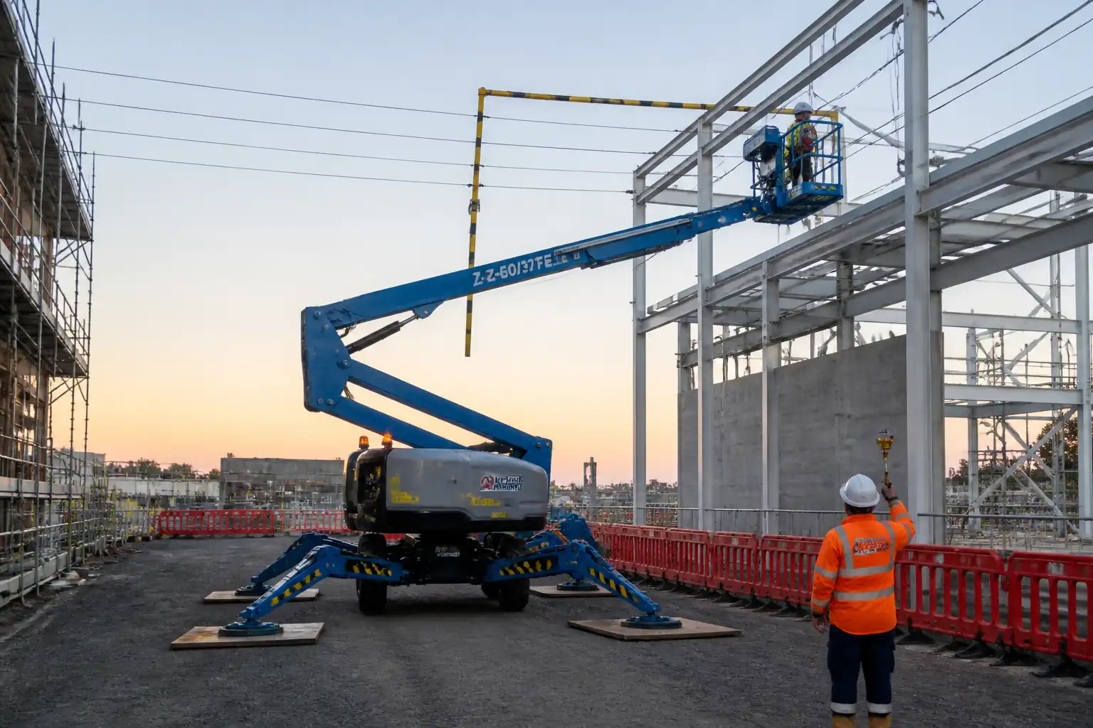
This method statement is used to define and communicate the approved procedure for carrying out method statement: mobile crane positioning, outrigger mat configuration, and ground bearing verification on site. It ensures the work is planned in advance, the correct resources and controls are in place, and all personnel understand responsibilities, sequence, quality requirements, and safety controls before work begins. It aligns site execution with the documented scope and acceptance expectations.
Who uses this method statement
This method statement is used by contractors, site supervisors, project engineers, QA/QC engineers, HSE officers, consultants, and client representatives. It serves as a shared reference for planning, execution, supervision, inspection, and approval of the activity on site.
When it is prepared and submitted
The method statement is prepared before the work activity starts and submitted as part of the pre-construction documentation package for review and approval.
Who reviews or approves it
The method statement is usually submitted to the client representative, consultant, resident engineer, or project management consultant for review and approval before the work commences.
Important approval note
This method statement is an AI-assisted editable starting point, not a pre-approved document. Before use on any project, all content must be reviewed and approved by the relevant parties (superintendent, principal contractor, or client representative) in accordance with your contract and project quality plan.
For example: if your specification requires a departure from a referenced standard, that departure must be documented and approved separately — this method statement will not capture that automatically. Always verify against your applicable drawings, specifications, and regulatory requirements.
Method statement content
Scope
Overview
This method statement covers the end-to-end process for:
- On-site positioning of a mobile crane with hydraulic outriggers.
- Determination, verification, and installation of timber or steel outrigger mats/pads.
- Ground bearing capacity verification for the crane foundation/working platform.
- Proximity checks to underground utilities and establishment of exclusion zones.
- Levelling of the crane and verification via spirit level/inclinometer and crane indicators.
- Safe initial boom extension, functional checks, and staged preloading/test lift.
Exclusions
- Crawler cranes and tracked plant working platforms (separate method required).
- Lifts over water, floating cranes, or barge-mounted operations.
- Complex tandem or multi-crane lifts (supplementary plan required).
Objectives
- Prevent crane overturning or excessive settlement by engineering the ground support and mats.
- Avoid strikes on underground utilities and overhead obstructions.
- Establish measurable acceptance criteria and inspection/testing steps governed by an ITP.
References
| Document Type | Reference / Number | Revision | Notes |
|---|---|---|---|
| Standard | BS 7121-1, BS 7121-3 [Verify applicability per region] | ||
| Standard | EN 13000 | ||
| Standard | ASME B30.5 [Verify per jurisdiction] | ||
| Standard | ISO 9927-1 | ||
| Standard | ISO 12480-1 | ||
| Standard | EN 1997-1 and EN 1997-2 | ||
| Guidance | CIRIA C703 | ||
| Guidance | Temporary Works forum (TWf) 2017:02 | ||
| Standards | ASTM D1556/D6938; BS 1377; EN 13286 [Verify per project] | ||
| Standards | EN 10025 (S355), EN 338 (timber classes), EN 13986 (wood-based panels) | ||
| Regulatory | [Verify per project HSE plan and local regulations: e.g., OSHA 1926 Subpart CC, LOLER/PUWER, HSE GS6] |
Responsibilities
| Role | Responsibility | Name / Party |
|---|---|---|
| AP | Lead | Contractor |
| TWE | Design check | Contractor/Designer |
| Geo Eng. | Ground verification | Consultant |
| Supervisor | Supervision | Contractor |
| Operator | Operation | Crane Supplier |
| Rigger | Rigging | Contractor |
| Utility Coord. | Locate services | Contractor |
| HSE | HSE compliance | Contractor |
| Surveyor | Survey | Contractor |
Resources
| Resource Type | Description | Quantity | Remarks |
|---|---|---|---|
| Personnel | Chartered or competent per local regulations | 1 | |
| Personnel | Design checker for mats/platform | 1 | |
| Personnel | Field testing and reporting | 1–2 | [Verify] |
| Personnel | Certified to operate specific crane model | 1 | |
| Personnel | In charge on site during lifts | 1 | |
| Personnel | Banksman and rigging crew | 2–4 | [Verify] |
| Personnel | Set-out and levelling | 1 | |
| Personnel | RAMS, permits, audits | 1 |
Materials
| Material | Specification / Grade | Quantity | Remarks |
|---|---|---|---|
| Timber | EN 338; EN 13986 | As per calc | |
| Steel | EN 10025 S355 | As per calc | |
| Aggregate | EN 13285/13286 or project spec | As required | |
| Geotextile | EN 13249 series | As required | |
| Timber | EN 338 | As required |
Equipment
| Equipment | Capacity / Type | Quantity | Inspection Required |
|---|---|---|---|
| Mobile crane | [Per plan] | 1 | Yes |
| OEM pads | [Per crane] | 4 | Yes |
| GPR/CAT | 1 set | Yes | |
| Level/Inclinometer | 1 set | Yes | |
| LWD/PLT | As required | Yes | |
| Anemometer | 1 | Yes |
Prerequisites
- Approved Lift Plan including crane model, radii, loads, maximum outrigger reaction (Rmax), swing-by-swing charts, and wind limits.
- Ground investigation data and/or platform design defining allowable bearing pressure qa_allow and platform build-up. If unknown, arrange site tests (e.g., LWD/PLT/CBR/DCP) to derive a conservative qa_allow [Verify per project specifications].
- Utility information: latest as-built drawings, permits, and on-site GPR/CAT survey completed; services marked and standoff distances briefed.
- Temporary Works Design (TWD) for platform and mats (if required by project category/class). Independent check as required.
- Permits: Permit-to-Work, Permit-to-Dig/Avoidance, Traffic Management Plan, Hot Work (if welding mats), and Power Line permit/notification where applicable [Verify per project HSE plan and local regulations].
- Calibrations: LMI, inclinometer, anemometer, survey equipment in date.
- Crew competence and certifications verified; toolbox talk undertaken covering hazards, exclusion zones, communications, and emergency plan.
- Weather check: forecast within crane limits; contingency for high winds.
- Access and egress routes prepared for crane arrival with bearing capacity confirmed.
Method Sequence
| Step | Activity | Description | Responsibility | Inspection / Hold Point |
|---|---|---|---|---|
| 1 | Pre-start briefing and set-out | Conduct toolbox talk; confirm roles, radio checks, exclusion zones; surveyor sets-out crane centreline, outrigger plan and mat extents. | Lifting Supervisor; Surveyor | Attendance; set-out check |
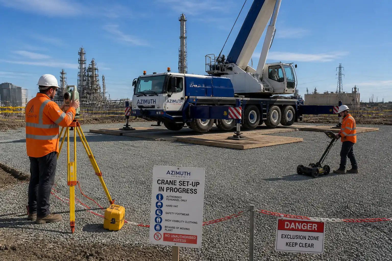
| 2 | Utility detection and permit | Review utility plans; perform GPR and CAT/Genny scan; mark services; establish stand-offs; issue Permit-to-Dig/Avoidance. | Utility Coordinator | Walkdown; permit review |
| 3 | Platform verification | Inspect and test working platform; confirm thickness, compaction, and levels; install geotextile if specified. | Geotechnical Engineer; QA/QC | Density/CBR/LWD tests |
| 4 | Outrigger reaction and mat sizing calculation | Determine Rmax from manufacturer or engineered lift calc; include dynamic/load factors (typ. 1.1–1.3) [Verify]. Compute required bearing area Areq = Rmax / qa_allow. Select mat(s) to provide Aeff ≥ Areq considering contact with soil; check mat bending/shear and deflection; verify punching under footpad. | AP; TWE | Design review |
| 5 | Mat delivery and inspection | Offload mats using rated slings; check grade marks, dimensions, damage, cleanliness, lifting points. | Riggers; QA/QC | Visual; documentation |
| 6 | Mat installation | Place mats to plan; ensure full surface contact; orient long axis perpendicular to anticipated shear where specified; avoid point packing; use full-contact cribbing if levelling needed; join mats per manufacturer (dog-bones/bolts) if specified. | Riggers; Supervisor | On-site check |
| 7 | Crane positioning | Spot crane over set-out; verify centreline; chock wheels; ensure tail swing clearance; confirm exclusion barriers in place. | Operator; Banksman | Spot check |
| 8 | Outrigger deployment | Extend beams per lift plan (full/partial positions allowed by manufacturer only); centre pads on mats; raise jacks to preload evenly until wheels just clear (per OEM). | Operator | Supervisor witness |
| 9 | Levelling and indicator checks | Level crane using outriggers; verify with onboard inclinometer and external level; check LMI zero, ATB, limit switches; set wind alarm. | Operator; Supervisor | Instrument check |
| 10 | Staged preload and settlement observation | Apply controlled preload by gently lifting superstructure and slewing without load over each quadrant; hold 60–120 s each; observe mats/ground. | Operator; Supervisor | Witness |
| 11 | Initial boom extension and test lift | Extend boom to minimum planned configuration; perform no-load functions; then test lift at ~5–10% of rated capacity at shortest planned radius; slew slowly through intended arc. | Operator; Supervisor | Witness (Hold point if specified) |
| 12 | Operations monitoring | During lifts, monitor wind, level, pads and mats; stop if alarms trigger or settlement/tilt observed; re-verify level after significant lifts. | Operator; Supervisor | Continuous |
| 13 | Demobilisation and reinstatement | Retract outriggers; inspect mats and platform; record any damage/settlement; remove mats; restore surface; close permits. | Supervisor; QA/QC | Final inspection |
Safety Controls (HSE)
Key task-specific hazards and controls
1) Hazard: Underground utility strike by outrigger/mat
- Likely consequence: Electrocution, service outage, flooding, explosion.
- Engineering/procedural control: Desktop utility review + on-site GPR/CAT scan; mark and maintain stand-offs; engineered bridging/protection if within standoff; Permit-to-Dig/Avoidance in force.
- Required PPE: Dielectric gloves when required, safety boots, helmet with chinstrap, hi-vis.
- Collective preventive measure: Physical barriers/Goalposts around service corridors; color-coded markings on ground.
- Inspection/permit/supervision: Utility permit signed by Utility Coordinator daily; Supervisor to verify markings before set-up; [Verify per project HSE plan and local regulations].
2) Hazard: Crane overturning due to inadequate ground bearing
- Likely consequence: Fatality, major plant loss, structural damage.
- Engineering/procedural control: Geotechnical verification; mat sizing calculations with FoS ≥ 1.3–1.5 [Verify]; staged preload with settlement measurement; stop-work triggers defined.
- Required PPE: Standard PPE; exclusion from line-of-fire during preload.
- Collective preventive measure: Exclusion zone min. radius equal to maximum boom length + 10% [Verify] during test lift; barricades and signage.
- Inspection/permit/supervision: ITP hold point for mat design approval and set-up inspection; AP/TWE sign-off.
3) Hazard: Out-of-level setup causing side loading/instability
- Likely consequence: Uncontrolled slew, tip risk.
- Engineering/procedural control: Platform level tolerance and crane levelling to ±0.5°; prohibit point packing; use full-contact cribbing/mats; survey check before preload.
- Required PPE: Standard PPE.
- Collective preventive measure: Dedicated banksman to observe pads during levelling; keep personnel clear of pad line.
- Inspection/permit/supervision: Supervisor to verify inclinometer readings; record in checklist.
4) Hazard: Mat slip or shear failure on sloping/soft ground
- Likely consequence: Sudden displacement, overturning.
- Engineering/procedural control: Surface preparation; anti-slip texture; mat connectors; limit slope ≤ 1% [Verify]; shear checks in design.
- Required PPE: Standard PPE.
- Collective preventive measure: Wheel chocks; edge stops/cribbing as designed.
- Inspection/permit/supervision: Set-up inspection with photos; re-check after preload.
5) Hazard: Overhead power lines or structures in slew path
- Likely consequence: Electrocution, collision.
- Engineering/procedural control: Survey overheads; establish statutory clearances; fit slew/reach limiters where available; spotter dedicated.
- Required PPE: Standard PPE; arc-rated where mandated near HV.
- Collective preventive measure: Goalposts with bunting; physical slew restriction (proximity alarms if available).
- Inspection/permit/supervision: Powerline permit; Supervisor to enforce exclusion; [Verify per local regulations].
6) Hazard: Wind gusts exceeding crane limits
- Likely consequence: Load swing, overload, loss of control.
- Engineering/procedural control: Anemometer at crane height; stop-work if wind ≥ OEM limit; derate as per chart; avoid sails.
- Required PPE: Standard PPE.
- Collective preventive measure: Weather monitoring board; secure loose materials.
- Inspection/permit/supervision: Supervisor to log wind hourly and at start of each lift.
7) Hazard: Pinch/crush during outrigger deployment and mat handling
- Likely consequence: Hand/foot injuries, fractures.
- Engineering/procedural control: Use taglines and approved lifting points; no hands under mats; keep clear of outrigger travel; lockout controls when placing mats.
- Required PPE: Impact gloves, steel-toe boots, eye protection.
- Collective preventive measure: Exclusion zone around each leg during movement; banksman control.
- Inspection/permit/supervision: Pre-task brief and dynamic risk assessment.
8) Hazard: Traffic interface with public/other site plant
- Likely consequence: Collision.
- Engineering/procedural control: Traffic Management Plan; segregated routes; banksman for reversing; lighting for night work.
- Required PPE: Hi-vis, helmet.
- Collective preventive measure: Barriers and signage; spotters.
- Inspection/permit/supervision: TMP permit; Supervisor checks.
9) Hazard: Hydraulic oil/fuel spill
- Likely consequence: Environmental contamination, slip hazard.
- Engineering/procedural control: Drip trays under connections; spill kits staged; immediate containment and reporting.
- Required PPE: Chemical-resistant gloves for cleanup; eye protection.
- Collective preventive measure: Bunded refuelling area; absorbent booms.
- Inspection/permit/supervision: Environmental permit/inspection; spill log.
10) Hazard: Night/low visibility operations
- Likely consequence: Miscommunication, strikes.
- Engineering/procedural control: Task lighting ≥ 200 lux at workface; radio comms; reflective markings on mats/legs.
- Required PPE: Hi-vis with retroreflective strips.
- Collective preventive measure: Light towers; exclude non-essential personnel.
- Inspection/permit/supervision: Night work permit; Supervisor lux check.
Environmental Controls
- Ground protection and rutting: Use specified working platform thickness; geotextile separation where weak subgrade; avoid trafficking outside platform; reinstate surfaces post-demob.
- Spill prevention: Stage spill kits; drip trays beneath hydraulic couplings; no refuelling over unprotected soil; report and clean spills immediately per spill response plan [Verify per project HSE plan].
- Noise and vibration: Schedule high-noise activities daytime; maintain equipment; hearing protection where >85 dB(A); monitor if adjacent receptors [Verify].
- Dust and mud tracking: Dampen haul roads in dry weather; wheel wash at egress; sweep paved areas.
- Waste management: Dispose of damaged timber/steel mats and packaging via approved waste streams; segregate wood/metal; consider reuse/refurbishment.
- Water management: Keep mats and operations outside drainage channels; protect nearby gullies with silt socks; no washout to ground.
- Ecology/trees: Respect root protection areas; no outriggers/mats within RPZ unless arborist-approved protection is installed [Verify].
- Material sourcing: Prefer FSC/PEFC-certified timber mats where specified; recycle steel mats at end of life.
Quality Assurance / Quality Control
Controls and tolerances
- Document control: Approved Lift Plan and TWD available at point of use; latest revisions only.
- Equipment calibration: LMI, inclinometer, anemometer, survey equipment within calibration validity.
- Platform QA: Density/compaction tests at minimum frequency 1 per 250 m² per layer [Verify]; LWD/CBR as specified; surface levels ±20 mm; slope ≤ 1% across outrigger span [Verify].
- Mat QA: Material certificates verified; visual acceptance on delivery; damage or warpage beyond limits rejected.
- Calculation check: Independent review by TWE as required; keep calculation sheets with inputs (Rmax, qa_allow, partial factors, load factors) and outputs (Aeff, mat section check).
- Acceptance metrics:
- Bearing pressure q = Rmax/Aeff ≤ qa_allow/γ [Verify γ].
- Crane level within ±0.5° prior to and during lifts.
- Settlement criteria: Immediate ≤ 10 mm per leg; differential ≤ 10 mm during preload [Verify].
- Utility stand-offs maintained and verified.
- Test lift: Function and partial load test witnessed; records filed.
- Surveillance: Supervisor checks every setup; re-check after any relocation or change in outrigger extension.
- Nonconformance: If criteria exceeded, stop-work, notify AP/TWE, implement corrective actions (increase mat area, improve platform, re-level, adjust lift plan) and re-inspect.
Records
- Lift Plan approval, TWD/TWC certificates, material certs, calibration certs, test reports, set-up and function checklists, settlement logs, as-built photos, permits, toolbox talks, close-out report.
Attachments
- Typical Lift Plan template and example for similar crane capacity.
- Outrigger Reaction and Mat Sizing Calculation Sheet (with example inputs/outputs).
- Working Platform Typical Detail (section and materials schedule).
- Pre-use and Set-up Inspection Checklist (Operator/Supervisor).
- Utility Survey and Permit-to-Dig/Avoidance template.
- Settlement Log sheet.
- Daily Wind/Weather Log.
- Close-out Inspection Report template.
This content is a read-only public reference. Download or customize to get an editable version.
ITP preview
The first inspection activities from the linked ITP for Method Statement: Mobile Crane Positioning, Outrigger Mat Configuration, and Ground Bearing Verification:
| Activity | Inspection / Test | Acceptance Criteria | Responsibility | Record |
|---|---|---|---|---|
| Lift Plan and calculations approval | Design/Calc Review | Approved Lift Plan; Mat/ground calc signed by AP/TWE | AP; TWE | Approved Plan; Calc Sheets |
| Utility detection and permit | GPR/CAT survey | Permit-to-Dig/Avoidance issued; services marked on ground | Utility Coordinator; HSE | Survey Report; Permit |
| Platform construction/verification | Density/CBR/LWD | 95% MDD; CBR/LWD per TWD; level and slope within limits [Verify] | Geo Eng.; QA/QC | QA Test Reports; Inspection Sheet |
Showing 3 of 10 inspection activities. View full ITP →
Related Inspection and Test Plan
An Inspection and Test Plan (ITP) is available for Method Statement: Mobile Crane Positioning, Outrigger Mat Configuration, and Ground Bearing Verification. The ITP defines the inspection activities, acceptance criteria, hold and witness points, responsible parties, and records required to verify the work described in this method statement.
View the Method Statement: Mobile Crane Positioning, Outrigger Mat Configuration, and Ground Bearing Verification ITP →Frequently asked questions
Continue with related Quollnet resources connected to this method statement.