Method Statement: Engineering Review and Approval Workflows for Complex Critical Lift Plans (>30 t or >80% Crane Capacity) – Method Statement
AI-assisted method statement with matching ITP, PDF download, and Excel export.
More than a static template
Unlike a downloadable Word or PDF template, this method statement is an AI-assisted editable starting point connected directly to a matching Inspection and Test Plan. Every section is structured, project-adaptable, and ready to export.
- AI-assisted drafting — Customize every section with AI for your specific project scope.
- Linked ITP — A matching inspection and test plan is generated alongside the method statement.
- Multiple export formats — Download as a formatted PDF or editable Excel spreadsheet.
- Editable starting point, not a final document — Review, verify, and adjust all content against your project requirements before use.
Static template vs. Quollnet workflow
| Feature | Static template | Quollnet |
|---|---|---|
| Project-specific content | Manual fill-in required | AI-assisted customization |
| Linked ITP | Separate document, no link | Matching ITP included |
| Export formats | Usually PDF only | PDF and Excel |
| Structured sections | Free-form layout | 13 standardized sections |
| Saved to your account | Local file only | Cloud-saved, reusable |
| Content accuracy | You verify everything | AI-assisted, you still verify |
| Cost | Often free but time-intensive | Free to customize and download |
What you can customize
When you save this method statement to your account, every section becomes editable. The following 13 sections are included:
- Scope — Defines the activity and its boundaries.
- References — Standards, specifications, and drawings.
- Responsibilities — Roles and accountabilities.
- Resources — Labour, plant, and equipment summary.
- Materials — Materials and compliance requirements.
- Equipment — Tools and equipment details.
- Prerequisites — Hold points and pre-conditions.
- Method sequence — Step-by-step construction sequence.
- Safety controls — HSE risk controls and PPE.
- Environmental controls — Environmental mitigation measures.
- QA/QC — Quality inspection and test requirements.
- ITP — Inspection and Test Plan table (has its own page).
- Attachments — Referenced drawings and documentation.
Why this method statement is used
This method statement is used to define and communicate the approved procedure for carrying out method statement: engineering review and approval workflows for complex critical lift plans (>30 t or >80% crane capacity) on site. It ensures the work is planned in advance, the correct resources and controls are in place, and all personnel understand responsibilities, sequence, quality requirements, and safety controls before work begins. It aligns site execution with the documented scope and acceptance expectations.
Who uses this method statement
This method statement is used by contractors, site supervisors, project engineers, QA/QC engineers, HSE officers, consultants, and client representatives. It serves as a shared reference for planning, execution, supervision, inspection, and approval of the activity on site.
When it is prepared and submitted
The method statement is prepared before the work activity starts and submitted as part of the pre-construction documentation package for review and approval.
Who reviews or approves it
The method statement is usually submitted to the client representative, consultant, resident engineer, or project management consultant for review and approval before the work commences.
Important approval note
This method statement is an AI-assisted editable starting point, not a pre-approved document. Before use on any project, all content must be reviewed and approved by the relevant parties (superintendent, principal contractor, or client representative) in accordance with your contract and project quality plan.
For example: if your specification requires a departure from a referenced standard, that departure must be documented and approved separately — this method statement will not capture that automatically. Always verify against your applicable drawings, specifications, and regulatory requirements.
Method statement content
Scope
Purpose
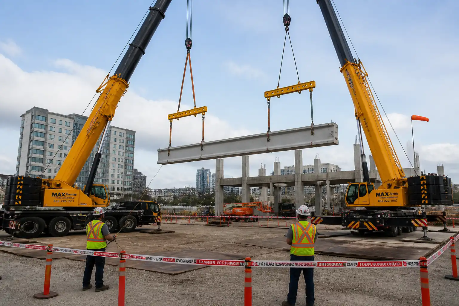
Define the engineering review, verification, approval, and permit-to-lift workflow for Complex Critical Lifts where lifted load exceeds 30 tons or the crane configuration operates at >80% of rated capacity, including engineered rigging design checks by a Professional Engineer (PE), dynamic loading calculation audits, and formal pre-lift permit sign-offs.
Inclusions
- Lift classification, data capture, and engineering inputs (CoG, rigging geometry, wind/sail area, travel path, lift zones).
- Rigging design and independent PE check; dynamic and environmental load allowances.
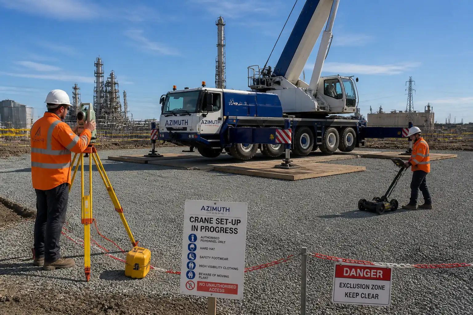
- Ground bearing assessment for crane set-up and matting design/verification.
- Configuration verification against OEM load charts and duty cycles.
- HAZID/constructability review; communication planning; emergency and exclusion zone planning.
- Pre-lift meeting, mock/test-lift, Go/No-Go criteria, and permit-to-lift sign-offs.
- Documentation control and records.
Exclusions
- Routine lifts (<30 tons and <80% capacity) unless otherwise classified by risk matrix.
- Detailed crane operation execution methodology (covered by separate method statement for lifting operations).
References
| Document Type | Reference / Number | Revision | Notes |
|---|---|---|---|
| ASME P30.1 | Planning and risk-based classification of lifts. | ||
| ASME B30.5 / B30.9 / B30.10 / B30.26 | Crane operations and rigging components requirements. | ||
| BS 7121-1 | Lift planning roles and responsibilities, AP and sign-offs. | ||
| BS EN 13000 | Mobile crane safety and rated capacity limiter functions. | ||
| ISO 12480-1 | General safe use principles and supervision. | ||
| ISO 9927 | Inspection regimes and records. | ||
| EN 13155 | Design/verification of lifting beams, spreaders, and attachments. | ||
| OSHA 1926.1400 | US regulatory requirements if applicable. | ||
| All values marked [Verify per project specifications]. |
Responsibilities
| Role | Responsibility | Name / Party |
|---|---|---|
| Client/Engineer | Approval authority | Client |
| Project Manager | Management | Contractor |
| AP/Lift Planner | Preparation | Contractor |
| PE (Structural/Mechanical) | Technical authority | Contractor/Consultant |
| HSE Manager | HSE oversight | Contractor |
| Crane Supplier Rep | OEM compliance | Supplier |
| Rigger Supervisor | Execution readiness | Contractor |
| Document Controller | Document control | Contractor |
Resources
| Resource Type | Description | Quantity | Remarks |
|---|---|---|---|
| Software | Structural/ring lift calculators, FEM or spreadsheet tools; CAD for rigging sketches. | Sufficient | |
| Documentation | Load drawings, CoG statements, lifting point certificates, sling/shackle certificates. | Complete set | |
| Personnel | AP/Lift Planner, PE (sign/seal), HSE Manager, Rigger Supervisor, Signalers, Crane Operator. | As required | |
| Instruments | Anemometer, load cell/dynamometer, total station or laser for radius verification, calibrated torque wrench. | 1 set/rig |
Materials
| Material | Specification / Grade | Quantity | Remarks |
|---|---|---|---|
| Rigging certificates | ASME B30.9/B30.26, EN 13155 | Complete certificates | Physical hardware inspected pre-lift; planning relies on documents |
| Crane docs | ISO 9927, local law [Verify] | Up-to-date |
Equipment
| Equipment | Capacity / Type | Quantity | Inspection Required |
|---|---|---|---|
| Crane | As selected | 1+ | |
| Spreader Beam | >= Required WLL | As required | |
| Load Cell | >110% of max expected line load [Verify] | 1 set | |
| Anemometer | 1 | ||
| Two-way Radios | Sufficient |
Prerequisites
- Confirm lift classification as Complex Critical (load >30 t or crane >80% rated capacity) per ASME P30.1/BS 7121-1 and project matrix.
- Obtain latest OEM load charts for exact crane configuration (boom length, jib, counterweight, outriggers/track).
- Obtain verified data for: load weight (+/- tolerance), center of gravity (CoG), dimensions, pick/set radii, lift path, sail area, lifting points and attachment capacities.
- Ground investigation and bearing capacity report for crane location; design/verify mats/spreaders as needed with target FoS 2.0–3.0 against bearing failure [Verify per project specifications].
- Identify overhead/underground utilities; implement isolation/permit with authority where required.
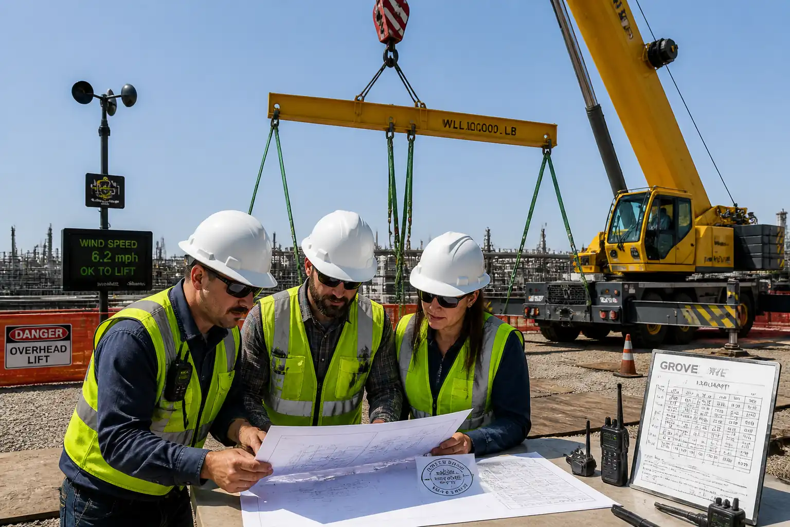
- Define environmental thresholds: maximum wind at hook height (typical 9–12 m/s for general lifts; lower for high sail areas) [Verify per project specifications].
- Confirm competency and certification of all personnel (AP, PE, operator, riggers, signalers) and equipment calibration certificates (LMI, load cells, anemometers) within valid dates.
- Prepare draft Lift Plan Dossier: risk assessment/HAZID, rigging drawings, calculation sheets, exclusion zones, traffic plan, communication plan, emergency rescue plan.
- Schedule HAZID/constructability review and pre-lift meeting with stakeholders (Contractor, Client/Engineer, Crane Supplier, HSE, PE).
Method Sequence
| Step | Activity | Description | Responsibility | Inspection / Hold Point |
|---|---|---|---|---|
| 1 | Lift Classification & Initiation | Classify the lift per ASME P30.1/BS 7121-1 using criteria: load >30 t or crane utilization >80%, unusual geometry, proximity to live plant, tandem lifts, or restricted radii. | AP/Lift Planner | Review |
| 2 | Data Capture & Verification | Capture verified weight, CoG, lifting point WLL, sling angles, radii, obstacles, wind exposure; check documents traceability. | AP / PE | Witness |
| 3 | Preliminary Rigging Design | Size slings/shackles/spreader beams; compute line loads with angle factors; apply DAF and environmental allowances. | PE (Design) | Review |
| 4 | Dynamic Loading Audit | Apply dynamic amplification factor (typ. 1.1–1.3 for mobile crane starts/stops) and wind load on projected area; check hoist speeds and shock load controls. | Independent PE (Checker) | Hold Point |
| 5 | Crane Selection & Utilization Check | Select crane and configuration; verify capacity at each radius and boom angle with charts; LMI/RCL settings defined. | AP / Crane Supplier Rep | Witness |
| 6 | Ground Bearing & Mat Design | Assess outrigger/tracks reactions; design mats/spreaders accordingly with FoS 2.0–3.0. | PE (Geotech/Structural) | Hold Point |
| 7 | HAZID & Constructability Review | Workshop reviewing proximity hazards, utilities, exclusion zones, traffic, communication, rescue plan. | HSE Manager (Chair) / AP | Witness |
| 8 | Lift Plan Dossier Compilation | Compile stamped calculations, rigging drawings, load charts, certificates, method statement extract, risk assessment, ITP, and checklists. | AP / Document Controller | Review |
| 9 | Client/Engineer Approval | Submit dossier for review; incorporate comments; obtain formal approval. | Contractor PM / AP | Hold Point |
| 10 | Pre-Lift Meeting (Toolbox) | Brief all participants: sequence, signals, exclusion zones, weather limits, Go/No-Go, emergency plan. | AP / HSE Manager | Witness |
| 11 | Site Readiness Verification | Confirm crane set-up, mats installed, exclusion/barriers, utilities isolated, signage, weather within limits. | AP / HSE / Client Rep | Hold Point |
| 12 | Mock/Test Lift | Hoist load 100–200 mm to verify balance, line loads, communication; adjust rigging if required. | AP / Rigger Supervisor / Operator | Witness |
| 13 | Permit-to-Lift Sign-off | Issue permit based on successful test-lift and site readiness; define validity period and conditions. | HSE Manager / Client Rep / AP | Hold Point |
| 14 | Post-Lift Review & Closeout | Capture lessons learned; archive records; update risk register. | AP / HSE / QA-QC | Review |
Safety Controls
Task-specific hazards and controls
- Hazard: Crane overload/instability leading to tip-over
- Likely consequence: Catastrophic equipment failure, fatalities, major property damage
- Engineering/procedural control: PE-verified calculations including DAF (typ. 1.1–1.3 [Verify]); utilization target ≤90% preferred; ground bearing check with FoS 2.0–3.0; LMI/RCL functional test; exclusion zone 1.5× maximum radius or as risk assessed [Verify]
- Required PPE: Hard hat, hi-vis, safety boots; exclusion-zone marshals with distinctive vests
- Collective preventive measure: Rigid barriers and spotters; designated crane pad with mats; wind monitoring at hook height
-
Inspection/permit/supervision: Pre-lift site readiness checklist; permit-to-lift; AP and HSE witness; daily crane pre-use inspection (ISO 9927)
-
Hazard: Rigging failure (sling/shackle/spreader)
- Likely consequence: Dropped load, severe injury/fatality
- Engineering/procedural control: Use certified components with WLL ≥ factored line loads; consider angle factors and D/d per ASME B30.9; EN 13155 for spreaders; remove components with defects; torque pins to spec
- Required PPE: Gloves, eye protection during rigging; steel-toe boots
- Collective preventive measure: Test-lift 100–200 mm; load cell monitoring; exclusion zone
-
Inspection/permit/supervision: Pre-use rigging inspection by competent rigger; certificates verified within 12 months [Verify]; PE sign-off on rigging design
-
Hazard: Load swing/wind effects
- Likely consequence: Loss of control, collision, line overload
- Engineering/procedural control: Set wind limits (typ. 9–12 m/s; lower for high sail area) [Verify]; taglines used where safe; smooth hoist controls; suspend lift if gusts exceed limit
- Required PPE: Gloves, helmets with chin strap where wind risk
- Collective preventive measure: Weather station/anemometer; staged hoisting speeds
-
Inspection/permit/supervision: Real-time wind logging; AP Go/No-Go authorization each shift
-
Hazard: Collision with structures or plant
- Likely consequence: Structural damage, process upset, injury
- Engineering/procedural control: Define lift path and swept envelope; spotters; proximity alarms; barricade encroachments
- Required PPE: Standard site PPE; radios for spotters
- Collective preventive measure: Physical barriers; banksman positions marked on ground
-
Inspection/permit/supervision: Pre-lift route walkdown; SIMOPS permit if near live plant [Verify per project HSE plan and local regulations]
-
Hazard: Powerline/energized equipment contact
- Likely consequence: Electrocution, arc flash, fire
- Engineering/procedural control: Maintain statutory clearances; de-energize or install physical barriers; dedicated spotter
- Required PPE: Dielectric gloves only as per electrical work scope; otherwise standard PPE and exclusion
- Collective preventive measure: Hard barricades; signage showing safe clearance
-
Inspection/permit/supervision: Electrical permit/LOTO; utility owner approval; AP/HSE verification
-
Hazard: Ground failure/underground services collapse
- Likely consequence: Crane settlement, overturning, utility rupture
- Engineering/procedural control: Subsurface survey (GPR/records); mat design; exclusion over tunnels/culverts unless engineered
- Required PPE: Standard site PPE
- Collective preventive measure: Mark no-go areas; use spreader mats per design
-
Inspection/permit/supervision: Ground bearing calc hold point; permit to break ground if excavation required
-
Hazard: Communication failure
- Likely consequence: Conflicting commands, shock loading
- Engineering/procedural control: Radio checks; single signaler protocol; hand signals per standard; backup radios
- Required PPE: Radio headsets where noise; high-vis for signalers
- Collective preventive measure: Dedicated channel with repeater if needed
-
Inspection/permit/supervision: Communication plan; AP to supervise pre-lift checks
-
Hazard: Personnel in pinch/crush zones during test lift
- Likely consequence: Serious injury
- Engineering/procedural control: Enforce exclusion around load; taglines; no body under suspended load
- Required PPE: Standard site PPE + cut-resistant gloves for tagline handlers
- Collective preventive measure: Barriers and banksman
- Inspection/permit/supervision: HSE observation; stop-work authority briefed to all
[All controls to be confirmed and adapted to project HSE plan and local regulations.]
Environmental Controls
- Potential hydraulic oil/fuel spills from crane
- Control: Drip trays under parked plant; spill kits at crane; operators trained in spill response
- PPE: Nitrile gloves, goggles during cleanup
- Collective measure: Secondary containment at refueling point; designated refueling area
-
Inspection/permit/supervision: Environmental permit if required; daily plant leak checks; spill log
-
Ground protection and soil compaction from crane mats
- Control: Use engineered mats to spread loads; avoid sensitive zones; reinstate ground post-lift
- PPE: Standard site PPE
- Collective measure: Define mat laydown and access routes
-
Inspection/permit/supervision: Environmental inspection prior/after works; photographic records
-
Noise during setup and test-lift
- Control: Limit hours; maintain equipment; use communication headsets to avoid shouting
- PPE: Hearing protection where >85 dB(A)
- Collective measure: Notify stakeholders; barriers where necessary
-
Inspection/permit/supervision: Noise monitoring as required [Verify]
-
Waste and damaged rigging disposal
- Control: Segregate and tag-out failed items; dispose via licensed waste stream
- PPE: Gloves, eye protection
- Collective measure: Locked scrap bins
-
Inspection/permit/supervision: Waste transfer notes; asset register update
-
Dust/mud from crane access routes
- Control: Road sweeping; wheel wash where needed
- PPE: Eye protection if dusty
- Collective measure: Speed limits; dampening
- Inspection/permit/supervision: Routine environmental patrols
QA/QC
Quality objectives
- Ensure all engineering calculations are checked and signed by a PE; where required, stamped per jurisdiction.
- Ensure compliance with ASME/BS/EN standards and OEM charts.
Key acceptance criteria [Verify per project specifications]
- Calculations incorporate DAF (typ. 1.1–1.3), wind loads (project-defined), angle factors, and rigging efficiency; resultant line loads ≤ WLL of slings/shackles/attachments with required factors of safety.
- Crane utilization: Target ≤90%; absolute ≤95% only with Client approval and additional controls.
- Ground bearing pressure ≤ allowable with FoS 2.0–3.0; mats installed per design.
- Wind speed at hook height ≤ limit specified in plan; measured and recorded.
- LMI/RCL and anti-two-block functional checks passed; radios function verified.
- Test-lift completed with measured line loads within ±10% of calculated values or within project-defined tolerance [Verify].
Document control
- All documents carry unique numbers, revision index, author/checker/approver signatures, and distribution matrix.
- Only controlled copies used at site; superseded documents retrieved.
Records and retention
- Lift Plan Dossier, signed calculations/drawings, certificates, ITP, permits, checklists, weather logs, test-lift records, meeting minutes retained per contract (typ. min. project duration + 10 years) [Verify].
Nonconformance and corrective action
- Deviations from plan trigger stop-work, NCR issuance, root cause analysis, and re-approval of revised documents prior to resumption.
Attachments
- Sample Critical Lift Plan Template (index, data sheets, drawings)
- Rigging Calculation Sheet (with angle factor and DAF fields)
- Crane Utilization Worksheet (per radius/boom length)
- Ground Bearing & Mat Design Template
- HAZID/Constructability Workshop Agenda and Action Log
- Pre-Lift Readiness Checklist
- Test-Lift Record and Load Log Sheet
- Communication Plan & Hand Signals Guide
- Emergency Response Plan (rescue of suspended load; area evacuation)
- Permit-to-Lift Form (with validity conditions and Go/No-Go criteria)
This content is a read-only public reference. Download or customize to get an editable version.
ITP preview
The first inspection activities from the linked ITP for Method Statement: Engineering Review and Approval Workflows for Complex Critical Lift Plans (>30 t or >80% Crane Capacity):
| Activity | Inspection / Test | Acceptance Criteria | Responsibility | Record |
|---|---|---|---|---|
| Lift classification and risk matrix confirmation | Review against ASME P30.1/BS 7121-1 | Classified as Complex Critical with documented justification | AP / HSE | Classification Form |
| Load/CoG data verification | Document traceability check | Manufacturer statement/drawings; CoG tolerance within plan limits | AP / PE | Data Register & Certificates |
| Rigging design calculations – independent PE check | Peer review and signature/stamp | All factored loads ≤ component WLL; drawings issued for use (IFU) | Independent PE (Checker) | Signed/Stamped Calcs & Drawings |
Showing 3 of 10 inspection activities. View full ITP →
Related Inspection and Test Plan
An Inspection and Test Plan (ITP) is available for Method Statement: Engineering Review and Approval Workflows for Complex Critical Lift Plans (>30 t or >80% Crane Capacity). The ITP defines the inspection activities, acceptance criteria, hold and witness points, responsible parties, and records required to verify the work described in this method statement.
View the Method Statement: Engineering Review and Approval Workflows for Complex Critical Lift Plans (>30 t or >80% Crane Capacity) ITP →Frequently asked questions
Continue with related Quollnet resources connected to this method statement.