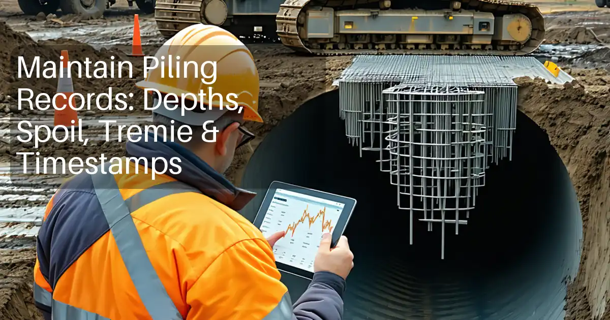
Pile Casing Inspection Checklist for Straightness, Joints, and Extraction
Definition: Pile Casing Inspection Checklist guides site engineers and inspectors to assess temporary and permanent pile casings for straightness, joints and weld quality, alignment, and planned extraction, excluding drilling logs.
- Verify straightness and alignment to prevent off-axis bored piles.
- Inspect joints, welds, collars, and locks for integrity and leaks.
- Plan casing extraction with equipment limits, timing, and contingencies.
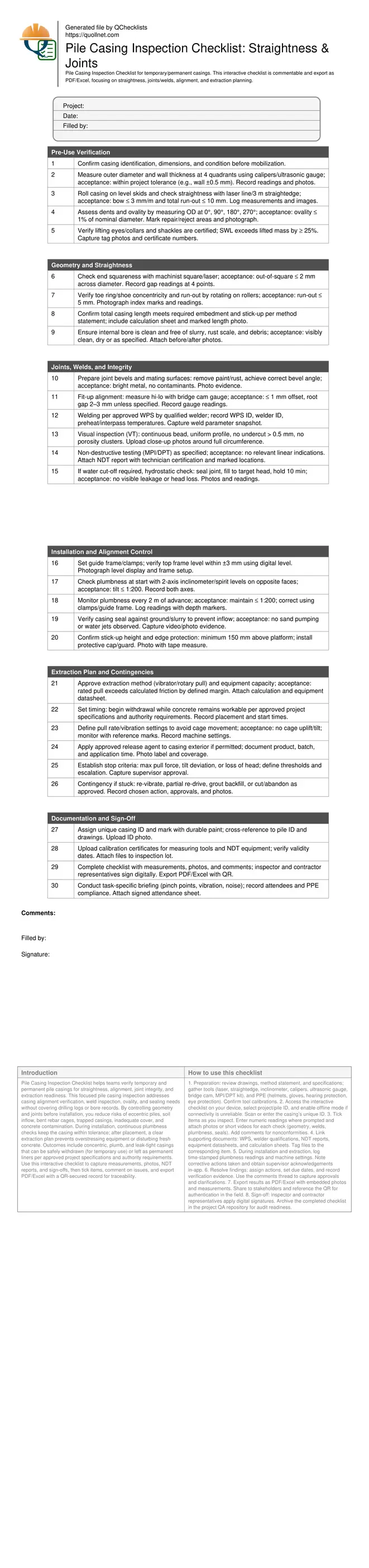
- Interactive, commentable checklist with export and QR code traceability.
Pile Casing Inspection Checklist helps teams verify temporary and permanent pile casings for straightness, alignment, joint integrity, and extraction readiness. This focused pile casing inspection addresses casing alignment verification, weld inspection, ovality, and sealing needs without covering drilling logs or bore records. By controlling geometry and joints before installation, you reduce risks of eccentric piles, soil inflow, bent rebar cages, trapped casings, inadequate cover, and concrete contamination. During installation, continuous plumbness checks keep the casing within tolerance; after placement, a clear extraction plan prevents overstressing equipment or disturbing fresh concrete. Outcomes include concentric, plumb, and leak-tight casings that can be safely withdrawn (for temporary use) or left as permanent liners per approved project specifications and authority requirements. Use this interactive checklist to capture measurements, photos, NDT reports, and sign-offs, then tick items, comment on issues, and export PDF/Excel with a QR-secured record for traceability.
- Ensure casing geometry meets project tolerances before use, preventing crooked piles, reinforcement clashes, and lost cover. Structured checks on straightness, squareness, ovality, and end preparation reduce rework and delays while improving concrete placement reliability and shaft stability.
- Validate joint fit-up, welding, and sealing with clear acceptance cues and required evidence. Visual, MPI/DPT, and optional hydrostatic tests confirm integrity in water-bearing soils, limiting laitance, inflow, and segregation risks during concreting and subsequent casing withdrawal.
- Interactive online checklist with tick, comment, and export features secured by QR code.
- De-risk extraction by sizing equipment to anticipated pull, setting timing and pull-rate limits, and defining stop criteria and contingencies. The plan minimizes damage to cages and fresh concrete while avoiding stuck casings and unplanned abandonment.
Pre-Use Verification
Geometry and Straightness
Joints, Welds, and Integrity
Installation and Alignment Control
Extraction Plan and Contingencies
Documentation and Sign-Off
Control Geometry: Straightness, Squareness, and Ovality
Geometry control begins before the casing reaches the guide frame. Rolling the tube on skids with a laser line or a 3 m straightedge reveals bows and flat spots that can force the pile off-axis. Measure OD and wall thickness at four quadrants to detect ovality and thin sections, which compromise seal performance and cause vibration chatter. End squareness is critical for concentric starts; even a few millimetres of bevel error can induce tilt. Verify toe ring/shoe concentricity so the cutting edge doesn’t track eccentrically. During installation, use a two-axis inclinometer or matched spirit levels to confirm tilt in orthogonal directions, and keep the guide frame level to within a few millimetres. These checks reduce rework, shorten setup times, and protect reinforcement. Record all measurements with photos and tie them to a unique casing ID for traceability and later comparison after extraction.
- Bow ≤ 3 mm/m; total run-out ≤ 10 mm.
- Ovality ≤ 1% from four-quadrant OD readings.
- End out-of-square ≤ 2 mm across diameter.
- Guide frame level within ±3 mm across span.
- Plumbness maintained at or better than 1:200.
Joints, Welds, and Sealing Integrity
Where casings are extended, reliable joints prevent leakage and misalignment. Start with clean bevels and proper gaps; document fit-up with a bridge cam gauge. Welding must follow an approved WPS with qualified welders, controlling preheat and interpass temperatures to avoid cracking. Visual inspection catches undercut, overlap, and porosity, while MPI or dye penetrant finds surface-breaking defects on ferromagnetic or nonmagnetic materials, respectively. In water-bearing strata, hydrostatic checks verify water-tightness before lowering. Keep a continuous evidence trail: WPS and welder IDs, VT photos around the circumference, NDT reports with indications and accept/reject fields. Address defects immediately to avoid delays during installation or extraction when rework is costly and disruptive.
- Record WPS ID, welder ID, and parameters.
- Use VT then MPI/DPT as specified.
- No relevant linear indications allowed.
- Hydro test joints where water cut-off required.
- Log and repair defects before use.
Plan and Control Casing Extraction
A proactive extraction plan minimizes damage to fresh concrete and reinforcement and prevents stuck casings. Size the vibratory hammer or puller to exceed anticipated skin friction with a clear margin, accounting for embedment length, soil type, and wall thickness. Time withdrawal while concrete remains workable as permitted, maintaining head to prevent necking. Set pull-rate and vibration limits to avoid cage uplift or lateral movement, using reference marks for visual confirmation. Establish stop criteria and contingencies: re-vibration, partial re-drive, backfilling with grout, or cutting and abandonment with approvals. Capture machine settings, start/finish times, and any anomalies. This documentation protects schedule and quality while providing a defensible record for stakeholders.
- Capacity > calculated pull with safety margin.
- Start withdrawal while concrete is workable.
- Monitor cage movement; stop if uplift occurs.
- Define stop criteria and escalation steps.
- Record settings, times, and outcomes.
How to Use This Interactive Pile Casing Inspection Checklist
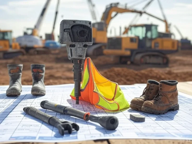
- Preparation: review drawings, method statement, and specifications; gather tools (laser, straightedge, inclinometer, calipers, ultrasonic gauge, bridge cam, MPI/DPT kit), and PPE (helmets, gloves, hearing protection, eye protection). Confirm tool calibrations.
- Access the interactive checklist on your device, select project/pile ID, and enable offline mode if connectivity is unreliable. Scan or enter the casing’s unique ID.
- Tick items as you inspect. Enter numeric readings where prompted and attach photos or short videos for each check (geometry, welds, plumbness, seals). Add comments for nonconformities.
- Link supporting documents: WPS, welder qualifications, NDT reports, equipment datasheets, and calculation sheets. Tag files to the corresponding item.
- During installation and extraction, log time-stamped plumbness readings and machine settings. Note corrective actions taken and obtain supervisor acknowledgements in-app.
- Resolve findings: assign actions, set due dates, and record verification evidence. Use the comments thread to capture approvals and clarifications.
- Export results as PDF/Excel with embedded photos and measurements. Share to stakeholders and reference the QR for authentication in the field.
- Sign-off: inspector and contractor representatives apply digital signatures. Archive the completed checklist in the project QA repository for audit readiness.
Call to Action
- Start Checklist Tick off tasks, leave comments on items or the whole form, and export your completed report to PDF or Excel—with a built-in QR code for authenticity.
- Download Excel - Pile Casing Inspection Checklist
- Download PDF - Pile Casing Inspection Checklist
- View Image - Pile Casing Inspection Checklist
Cite & Embed
“Pile Casing Inspection Checklist by Quollnet”
with a link to
this source page.
FAQ
Question: What tolerances are commonly used for casing straightness and plumbness?
Question: How should I inspect welds on-site when conditions are wet or raining?
Question: When is the right time to extract temporary casing during concreting?
Question: What evidence should I capture to satisfy quality assurance and audits?
Related Articles
Broader reading and guidance connected to this checklist topic.


Related Checklists
Keep the workflow moving with nearby templates chosen from similar checklist content.