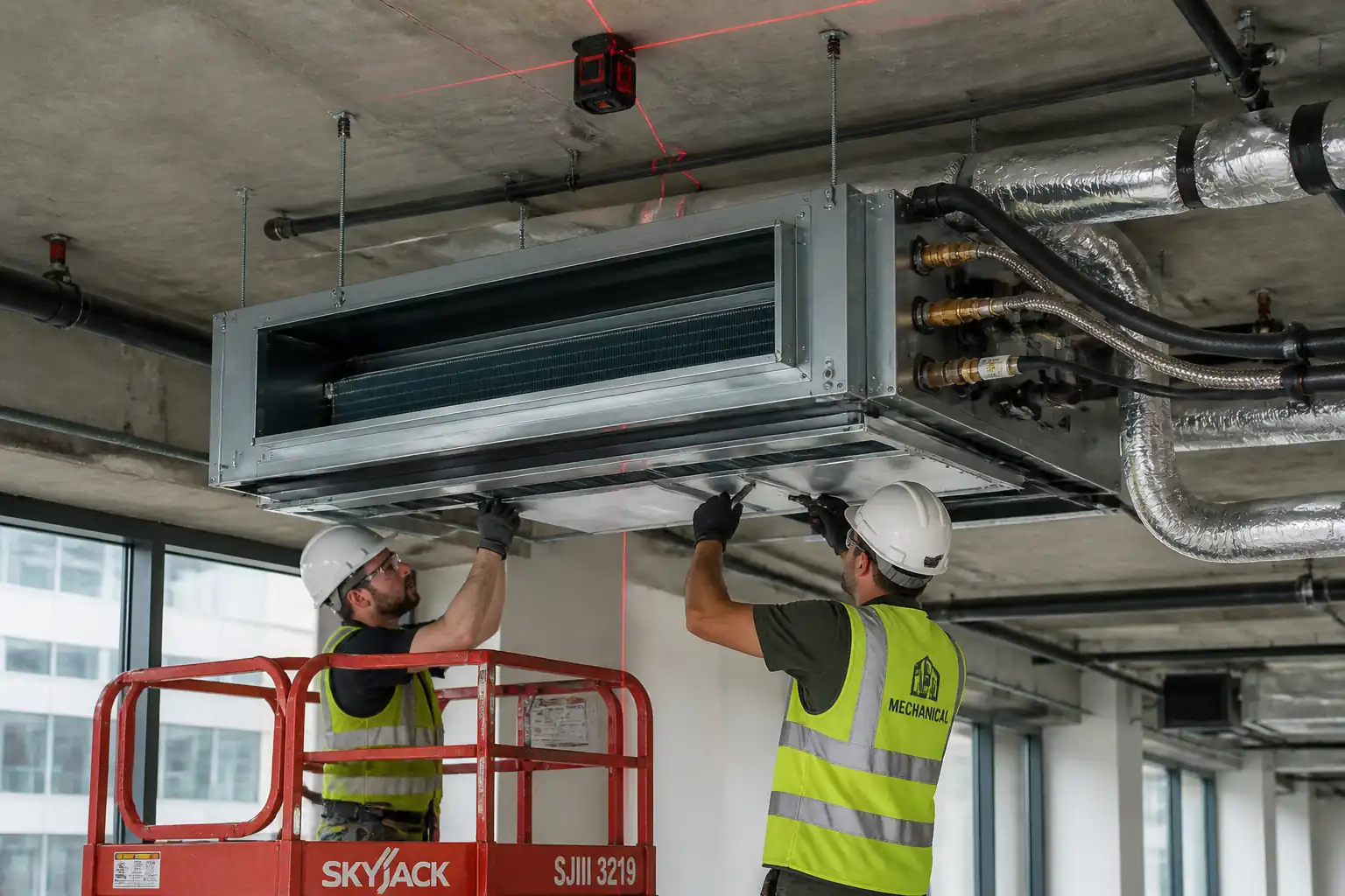

Method Statement: Installation of Ceiling-Suspended Fan Coil Units (FCUs) – Method Statement
AI-assisted method statement with matching ITP, PDF download, and Excel export.
More than a static template
Unlike a downloadable Word or PDF template, this method statement is an AI-assisted editable starting point connected directly to a matching Inspection and Test Plan. Every section is structured, project-adaptable, and ready to export.
- AI-assisted drafting — Customize every section with AI for your specific project scope.
- Linked ITP — A matching inspection and test plan is generated alongside the method statement.
- Multiple export formats — Download as a formatted PDF or editable Excel spreadsheet.
- Editable starting point, not a final document — Review, verify, and adjust all content against your project requirements before use.
Static template vs. Quollnet workflow
| Feature | Static template | Quollnet |
|---|---|---|
| Project-specific content | Manual fill-in required | AI-assisted customization |
| Linked ITP | Separate document, no link | Matching ITP included |
| Export formats | Usually PDF only | PDF and Excel |
| Structured sections | Free-form layout | 13 standardized sections |
| Saved to your account | Local file only | Cloud-saved, reusable |
| Content accuracy | You verify everything | AI-assisted, you still verify |
| Cost | Often free but time-intensive | Free to customize and download |
What you can customize
When you save this method statement to your account, every section becomes editable. The following 13 sections are included:
- Scope — Defines the activity and its boundaries.
- References — Standards, specifications, and drawings.
- Responsibilities — Roles and accountabilities.
- Resources — Labour, plant, and equipment summary.
- Materials — Materials and compliance requirements.
- Equipment — Tools and equipment details.
- Prerequisites — Hold points and pre-conditions.
- Method sequence — Step-by-step construction sequence.
- Safety controls — HSE risk controls and PPE.
- Environmental controls — Environmental mitigation measures.
- QA/QC — Quality inspection and test requirements.
- ITP — Inspection and Test Plan table (has its own page).
- Attachments — Referenced drawings and documentation.
Why this method statement is used
This method statement is used to define and communicate the approved procedure for carrying out method statement: installation of ceiling-suspended fan coil units (fcus) on site. It ensures the work is planned in advance, the correct resources and controls are in place, and all personnel understand responsibilities, sequence, quality requirements, and safety controls before work begins. It aligns site execution with the documented scope and acceptance expectations.
Who uses this method statement
This method statement is used by contractors, site supervisors, project engineers, QA/QC engineers, HSE officers, consultants, and client representatives. It serves as a shared reference for planning, execution, supervision, inspection, and approval of the activity on site.
When it is prepared and submitted
The method statement is prepared before the work activity starts and submitted as part of the pre-construction documentation package for review and approval.
Who reviews or approves it
The method statement is usually submitted to the client representative, consultant, resident engineer, or project management consultant for review and approval before the work commences.
Important approval note
This method statement is an AI-assisted editable starting point, not a pre-approved document. Before use on any project, all content must be reviewed and approved by the relevant parties (superintendent, principal contractor, or client representative) in accordance with your contract and project quality plan.
For example: if your specification requires a departure from a referenced standard, that departure must be documented and approved separately — this method statement will not capture that automatically. Always verify against your applicable drawings, specifications, and regulatory requirements.
Method statement content
Scope
Work Included
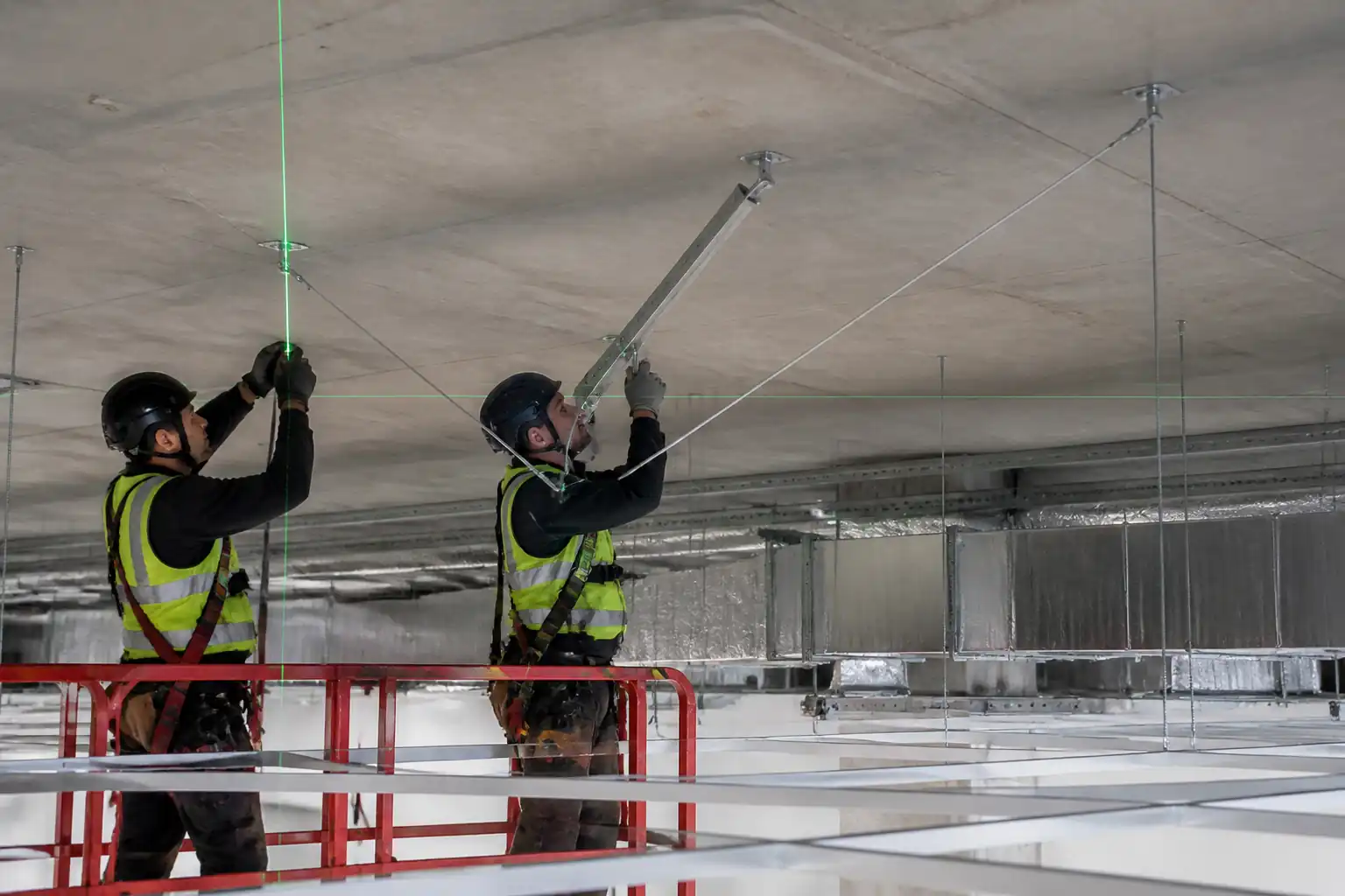
- Layout, marking, and installation of post-installed anchors in soffits for FCU suspension.
- Supply and installation of hanger rods, channels, and vibration isolators (spring/neoprene) for ceiling-suspended FCUs.
- Safe lifting, positioning, and fixing of FCUs to isolators; precise leveling/alignment per manufacturer.
- Connection of flexible air ducts, spigots, and plenums; sealing to required duct leakage class [Verify per project specifications].
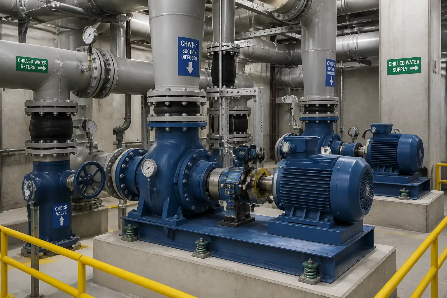
- Installation and connection of chilled water (CHW) valve packages (isolation valves, control valve, strainer with blowdown, unions, pressure/temperature test points), and flexible braided hoses.
- Installation of condensate drain, P-trap sizing and arrangement, cleanouts, and functional/leak testing.
- Insulation and vapor barrier continuity for CHW pipework, valves/boxes, flexible hoses, and condensate drains, including sealing of penetrations.
- Tagging/labeling, supports, and identification arrows; prelim functional checks (valve actuation, fan run test if power available).
- QA/QC inspections, records, and HOLD POINT: pre-close inspection prior to ceiling closure.
Exclusions
- Final TAB and system commissioning beyond pre-commissioning checks [By others unless stated].
- Permanent power supply and BMS programming [By others unless stated].
- Ceiling grid/tiles installation and builders' finishing works.
Interfaces
- Coordination with architectural ceilings, lighting, fire protection, and other MEP services.
- Coordination with structural engineer for anchor types/locations in load-bearing elements.
References
| Document Type | Reference / Number | Revision | Notes |
|---|---|---|---|
| ACI 318 (Anchoring to Concrete) and ACI 355.2 / ACI 355.4 (Qualification of Post-Installed Mechanical/Chemical Anchors) | Anchor selection, embedment, spacing, edge distances [Verify per project structural design] | ||
| SMACNA HVAC Duct Construction Standards; DW/144 (if UK projects) | Duct/flexible connector installation, leakage classes, sealing | ||
| UL 181 / UL 181A/B for flexible air ducts and duct sealing materials | Flexible duct and mastic/tape classifications | ||
| ASME B31.9 (Building Services Piping) / BS EN 13480 (Metallic Industrial Piping) | CHW piping workmanship and testing guidance [Verify project code basis] | ||
| ISO 5208 (Industrial valves—Pressure testing) / EN 12266-1 | Valve leakage testing criteria reference | ||
| International Mechanical Code (IMC) or local mechanical code | Condensate drain slope, trap, and termination [Verify per local code] | ||
| ASTM A307 (Carbon Steel Bolts), ASTM A563 (Nuts), ASTM F436 (Washers) | Threaded rod and fastener properties | ||
| AHRI 410 (Forced-Circulation Air-Cooling and Air-Heating Coils) | FCU coil ratings and performance—installation per manufacturer | ||
| Manufacturer installation manuals (FCU, isolators, anchors, valves, hoses, insulation) | Project-specific mandatory instructions [Verify per approved submittals] | ||
| Project Specifications and Approved Shop Drawings/Coordination Models | Governing requirements where more stringent |
Responsibilities
| Role | Responsibility | Name / Party |
|---|---|---|
| Mechanical Engineer | Mechanical Engineer | Contractor |
| MEP Supervisor | Site MEP Supervisor/Foreman | Contractor |
| QA/QC Engineer | QA/QC Engineer | Contractor |
| HSE Officer | HSE Officer | Contractor |
| Lifting Supervisor | Rigger/Lifting Supervisor | Contractor |
| Document Controller | Planner/Document Controller | Contractor |
| Consultant | Consultant/Engineer | Consultant |
Resources
| Resource Type | Description | Quantity | Remarks |
|---|---|---|---|
| Staff | 1 | On-call for technical decisions | |
| Staff | 1 | Full-time during inspections | |
| Staff | 1 | Shared resource; conducts PTW and audits | |
| Staff | 1 | Leads crew | |
| Trades | 2–3 | Valve package and CHW connections | |
| Trades | 1–2 | Flexible duct/spigot works | |
| Trades | 1–2 | CHW and condensate insulation | |
| Trades | 1 | Terminations and control valve actuator [If in scope] | |
| Trades | 2 | Lifting and positioning of FCU |
Materials
| Material | Specification / Grade | Quantity | Remarks |
|---|---|---|---|
| Ceiling-suspended FCU | Manufacturer standard; corrosion-protected casing; fan/motor per submittal | As per BOQ | AHRI 410 rated coils; factory drain pan with overflow provision |
| Post-installed anchors (mechanical wedge/undercut or adhesive) | Design per ACI 318; embedment/edge distances per calc [Verify per project] | As required | Install per ACI 355 and manufacturer torque/setting |
| Threaded rods, nuts, washers | ASTM A307 bolts/rods, ASTM A563 nuts, ASTM F436 washers | As required | Hot-dip galvanized where specified [Verify] |
| Vibration isolators (hangers) | Load rating to exceed 1.2 × operating load; corrosion-resistant hardware | Per FCU supports | Neoprene or spring isolators as per schedule |
| Flexible air duct/connector | UL 181 Class 1; mastic/tape UL 181A-M/181B-FX | As required | UL 181 listed; with clamps/bands |
| CHW valve package | Isolation ball valves to ISO 5208 leakage rate A; strainer mesh 0.6–1.0 mm [Verify] | Per FCU | Control valve may be PICV or 2-way with DPCV—per design |
| Flexible braided hoses | Stainless steel braid; rubber/PTFE liner; ISO 10380 compliant [Verify] | 2 per FCU (S/R) | With swivel ends to avoid twist |
| Condensate drain piping and P-trap | uPVC/PVC Sch 40 per ASTM D1785; cement ASTM D2564; slope ≥1% | As required | Solvent cement and primer compatible |
| Pipe insulation (CHW and condensate) | Closed-cell elastomeric foam per ASTM C534 Type II; thickness 13–25 mm [Verify] | As required | Seal all seams for vapor barrier continuity |
| Identification labels and flow arrows | Mechanical service labeling per project standards [Verify] | As required | Heat-shrink or engraved labels per spec |
Equipment
| Equipment | Capacity / Type | Quantity | Inspection Required |
|---|---|---|---|
| Scissor lift/MEWP | Working height as required | 1–2 | Daily inspection checklist |
| Rotary hammer drill (SDS) | Ø per anchor spec | 2 | PAT and guard checks |
| Concrete scanner | Depth ≥150 mm | 1 | Calibration cert valid |
| Blow-out pump/brush set and vacuum (HEPA) | 1 | Clean filter, test suction | |
| Torque wrench | 1 | Calibration cert ≤6 months | |
| Anchor pull-out tester | Up to 20 kN | 1 | Calibration cert valid |
| Laser level/digital inclinometer | 1 | Calibration cert valid | |
| Chain block and soft slings | SWL ≥ 2 × load | 1 | LOLER/third-party cert |
| Hydrostatic test pump and calibrated gauge | Up to test pressure | 1 | Gauge calibration cert |
| Pipe press tool / threading machine | 1 | Daily checks |
Prerequisites
Approvals and Documentation
- Approved shop drawings, coordination model, structural approvals for anchors, and manufacturer installation manuals available at site.
- Approved Materials Inspection Requests (MIR) for FCUs, anchors, isolators, valves, hoses, insulation, and drains.
- Lifting plan and rigging certificates; operators certified for MEWP/rigging.
- Calibrations valid for torque wrenches, pull testers, pressure gauges, laser levels, scanners.
Site Conditions and Permits
- Permits to Work (PTW): Working at Height, Lifting, Hot Work (only if brazing), and Electrical Isolation as applicable [Verify per project HSE plan and local regulations].
- Confirm clear work area, temporary lighting, protection of finished surfaces, and safe access/egress.
- Coordination clearance: verify no clashes with fire sprinkler mains/heads, lighting, cable trays, other ducts.
- Verify soffit substrate (concrete strength, thickness, presence of PT cables/rebar) using scanner and records.
- Availability of CHW isolation for tie-ins/pressure test drains; access to water and approved drain for hydro/flush water disposal.
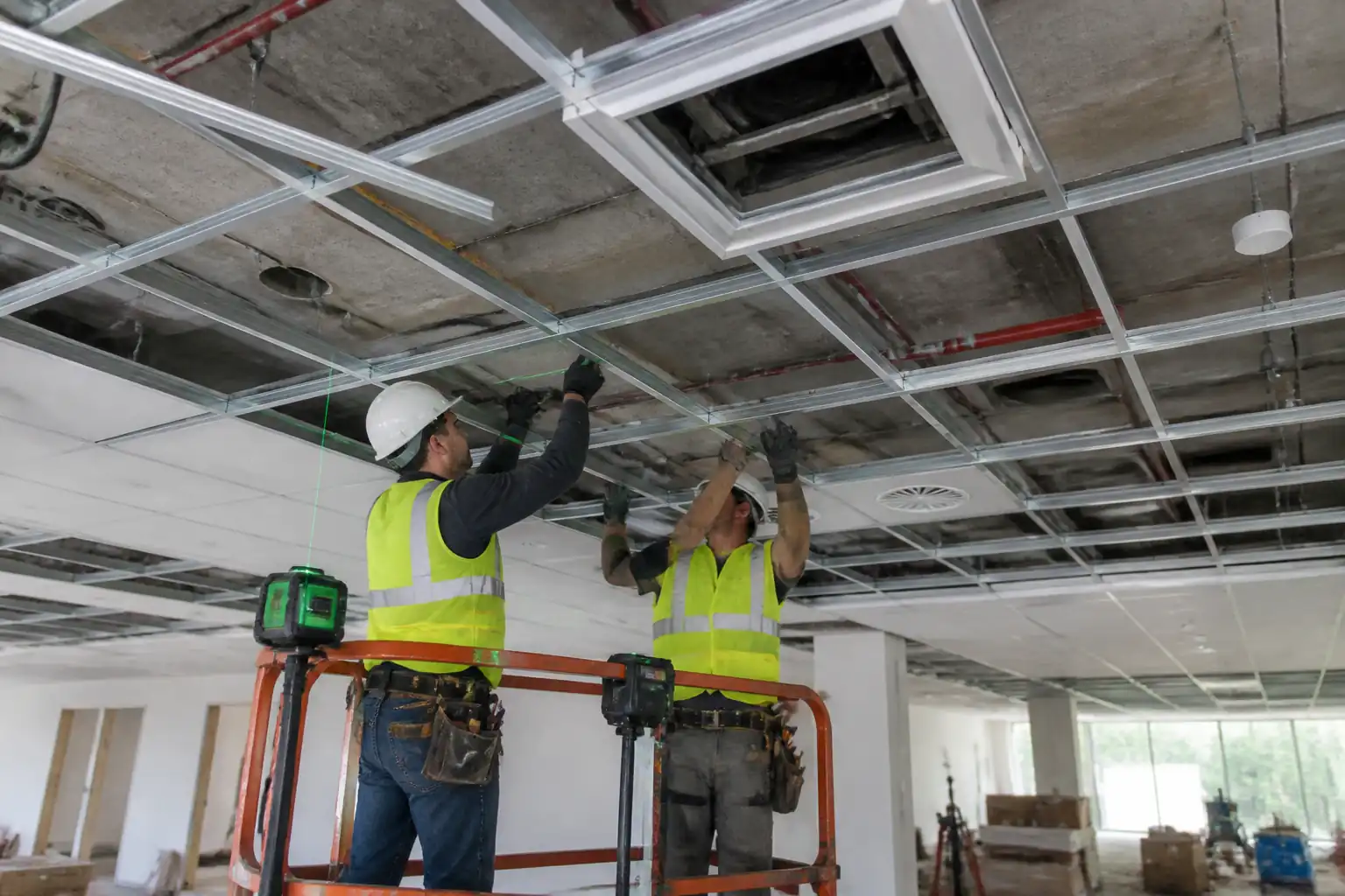
- Confirm ceiling grid datum; set benchmark elevation for FCU bottom relative to ceiling plane.
Method Sequence
| Step | Activity | Description | Responsibility | Inspection / Hold Point |
|---|---|---|---|---|
| 1 | Setting out & coordination | Mark FCU location, hanger points per approved drawings/manufacturer lifting points. Reference laser datum for bottom-of-FCU and ceiling plane. | MEP Supervisor | Internal check |
| 2 | Scan, drill, and install anchors | Scan soffit to avoid PT cables/rebar. Drill per anchor spec. Clean holes (brush-blow-vacuum). Install anchors to required embedment/torque; cure adhesive anchors per TDS. | Foreman | QA/QC and third-party as required |
| 3 | Install hanger rods and isolators | Fix threaded rods with double nuts and washers. Install spring/neoprene hanger isolators at specified elevations. | Foreman | QA/QC |
| 4 | Lift and suspend FCU | Under controlled lift, raise FCU using MEWP/chain block. Align with isolators and secure. Remove transport locks where applicable. | Lifting Supervisor | HSE and QA/QC |
| 5 | Level and final alignment | Adjust nuts to level FCU. If manufacturer requires fall to drain, set slight slope toward drain pan outlet. | MEP Supervisor | QA/QC |
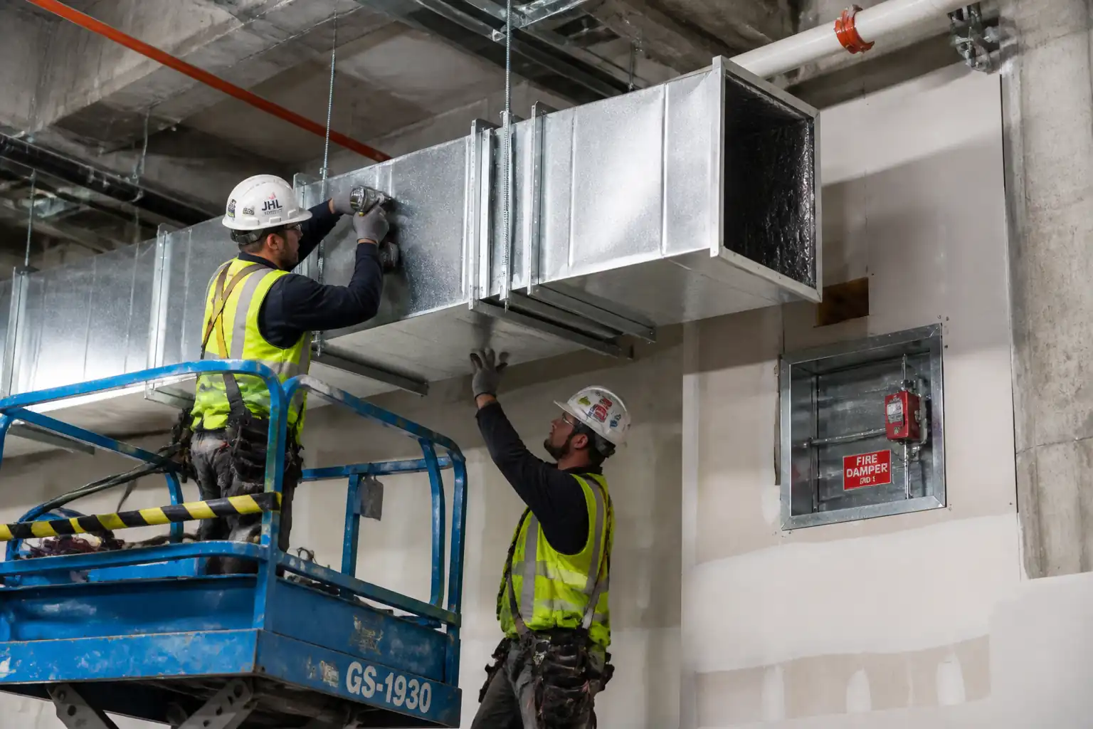
| 6 | Flexible duct/spigot connection | Connect supply/return air to FCU spigots. Keep flex length short and supported; avoid sharp bends; seal joints with UL 181 mastic/bands. | Duct Installer | QA/QC |
| 7 | Install CHW valve package and hoses | Fit isolation valves, control valve/actuator, Y-strainer with drain, unions, PT plugs as per flow direction. Connect braided hoses without twist; support to avoid strain on FCU. | Pipefitter | QA/QC |
| 8 | Hydrostatic test (local) | Isolate and pressure test FCU valve package and local CHW connections before insulation. | QA/QC Engineer | Consultant witness (Hold) |
| 9 | Condensate drain & P-trap installation | Install drain from pan outlet with cleanout and P-trap. Maintain continuous fall to riser; provide air break as required by code. | Pipefitter | QA/QC |
| 10 | Insulation and vapor barrier | Insulate CHW valves/hoses (with boxes as needed) and condensate drains. Seal all seams/joints to maintain vapor barrier; carry insulation over supports. | Insulator | QA/QC |
| 11 | Electrical/BMS terminations | Connect control valve actuator, fan motor, float switch, and thermostat as applicable. Dress cables; secure away from hot/cold surfaces. | Electrician/BMS Tech | QA/QC |
| 12 | Pre-functional checks | Clean strainer basket; confirm valve positions; verify airflow path unobstructed; remove debris; run fan briefly if power available. | MEP Supervisor | QA/QC |
| 13 | QA/QC Hold Point – Pre-ceiling closure | Offer WIR to Consultant for inspection of supports, connections, insulation continuity, labeling, and as-built photos before any ceiling closure. | QA/QC Engineer | Consultant HOLD |
Health, Safety, and Environment (HSE) – Task-Specific Safety Controls
Key Hazards and Controls
- Hazard: Overhead lifting of FCU; falling load.
- Likely consequence: Serious injury/fatality, property damage.
- Engineering/procedural control: Approved lifting plan; exclusion zone with barrier tape; pre-use inspection of chain blocks/slings; lift under Lifting Supervisor; tag lines; no standing under load.
- Required PPE: Hard hat, safety boots, cut-resistant gloves, eye protection.
- Collective preventive measure: MEWP with guardrails; secondary retention (safety wires) on heavy components where specified.
-
Inspection/permit/supervision: Lifting PTW; 3rd-party certs for lifting gear; recorded pre-lift checklist; competent rigger on site.
-
Hazard: Drilling overhead into soffit; striking PT cables/rebar or embedded services; falling dust/debris.
- Likely consequence: Structural damage, electrocution, injury to eyes/respiratory system.
- Engineering/procedural control: Concrete scanning and marked safe zones; drilling stoppers for depth control; dust extraction attachments; use catch trays; isolate nearby electrical circuits where necessary.
- Required PPE: Safety glasses/face shield, FFP2/FFP3 respirator, gloves, hearing protection.
- Collective preventive measure: Task lighting; debris nets; spotter to control area.
-
Inspection/permit/supervision: Permit to Drill where applicable; toolbox talk; equipment PAT and guards verified.
-
Hazard: Working at height (MEWP/step-ups) in ceiling voids.
- Likely consequence: Falls, entrapment, sprains.
- Engineering/procedural control: MEWP operator certification; pre-use inspection; firm level floor; do not overreach; maintain 3-point contact on ladders; keep tools tethered.
- Required PPE: Harness with lanyard if required by MEWP type, non-slip footwear, helmet with chin strap.
- Collective preventive measure: Proper access platforms instead of improvised stands; edge protection where floor openings exist.
-
Inspection/permit/supervision: Working at Height PTW; supervisor to monitor; daily MEWP checklist.
-
Hazard: Manual handling of FCU and materials in confined ceiling spaces.
- Likely consequence: Musculoskeletal injuries, crush/pinch points.
- Engineering/procedural control: Use mechanical aids (MEWP/chain block); team lifts; planned handling route; keep hands clear during mating of isolators.
- Required PPE: Gloves, safety boots.
- Collective preventive measure: Pre-stage materials; reduce carry distances.
-
Inspection/permit/supervision: Manual handling briefing; supervision during lift.
-
Hazard: Hydrostatic testing and unexpected pipe rupture.
- Likely consequence: Water jet injury, flooding, slip hazards, damage to finishes.
- Engineering/procedural control: Temporary caps and restraints; pressure relief; slow pressurization; barricade area; use calibrated gauge.
- Required PPE: Eye protection, gloves, boots with slip resistance.
- Collective preventive measure: Spill trays; floor protection; wet vac available.
-
Inspection/permit/supervision: Test permit/log; gauge calibration check; supervisor present.
-
Hazard: Electrical/BMS terminations near metal casings.
- Likely consequence: Electric shock, short circuits.
- Engineering/procedural control: Lockout/Tagout (LOTO) for circuits; verify dead; correct fusing; strain relief and grommets; segregate power/control cables.
- Required PPE: Insulated tools, arc-rated gloves as required, eye protection.
- Collective preventive measure: Temporary power RCDs.
-
Inspection/permit/supervision: Electrical PTW; testing by competent electrician.
-
Hazard: Use of adhesives/mastics and insulation in confined areas (VOC exposure).
- Likely consequence: Respiratory/skin irritation, fire risk.
- Engineering/procedural control: Use low-VOC products where available; ensure ventilation; follow SDS; no ignition sources.
- Required PPE: Nitrile gloves, FFP2 mask (as needed), safety glasses.
- Collective preventive measure: Local exhaust or fans.
- Inspection/permit/supervision: SDS available; Hot Work PTW only if brazing is required [Verify per project HSE plan and local regulations].
Environmental Controls
Controls
- Dust and noise: Use drills with dust extraction and HEPA vac; wet methods not typically required; schedule high-noise tasks outside sensitive hours. Monitor noise per project limits [Verify].
- Waste segregation: Collect scrap metal (rods/channels), plastic (flex duct offcuts), and cardboard separately. Dispose adhesive/chemical containers as hazardous if labeled.
- Water management: Capture hydrotest water; discharge to approved drains only; prevent silt/debris entry via strainers; no discharge to landscape.
- Spill prevention: Use drip trays under valve package during testing; keep absorbent pads/spill kits at workface.
- Material storage: Store FCUs and insulation dry, off the floor, protected from UV and moisture.
- Energy and emissions: Switch off MEWPs and tools when not in use; minimize idling of delivery vehicles.
- Protection of finishes: Lay protective sheeting; avoid staining from primer/cement; immediate cleanup of any adhesive spills.
- Compliance: Follow project Environmental Management Plan and local regulations [Verify].
Quality Assurance / Quality Control
QA/QC Controls
- Submittals: Use only approved makes/models per MIR. Maintain on-site copies of approved drawings and manufacturer instructions.
- Anchors: Verify type, diameter, embedment, spacing, and edge distances per design. Record torque values and curing times for adhesive anchors. Proof-test sampling: 1 per 20 anchors per area or minimum 3 per day [Verify per project].
- Hangers/isolators: Check rod plumb (±2°), thread engagement (≥1.5×Ø), isolator deflection near design (±2 mm). Provide lock nuts and anti-vibration washers.
- Level/alignment: Record digital level readings; ensure FCU level within ±1 mm/m unless manufacturer requires fall to drain (typ. 0.5–1.0%).
- Duct connections: Confirm flex length ≤1.2–1.5 m and bend radius ≥1×Ø; joints sealed to specified leakage class; install balancing devices where shown.
- CHW valve package: Check valve orientation, union accessibility, strainer blowdown clearance; actuator stroke and fail position per controls strategy.
- Hydrostatic testing: Pressure, duration, and acceptance per ITP; protect finishes and record gauge serials and calibration.
- Condensate system: Slope ≥1%; trap height sized to fan negative pressure; perform leak and functional tests by filling drain pan; confirm float switch cutout if provided.
- Insulation/vapor barrier: Thickness per spec; no gaps; seams sealed; insulation carried over hangers; valve boxes accessible and sealed.
- Documentation: Maintain checklists, photos before ceiling closure, as-built markups, labels and tag lists. Close all punch items before HOLD point release.
- Measuring/test equipment: Use calibrated instruments; keep certs available.
Attachments
Attachments/Records
- Approved shop drawings and coordinated reflected ceiling plans.
- Manufacturer installation manuals: FCU, anchors, isolators, valves, hoses, insulation, flexible ducts.
- Structural anchor design/calculations and anchor layout drawings.
- Lifting plan and lifting gear third-party certificates.
- Calibration certificates: torque wrench, pull tester, gauges, laser level, scanner.
- Checklists: layout, supports, valve package, duct connection, insulation, pre-functional.
- Test reports: anchor pull-out, hydrostatic test, condensate drain test.
- WIR/MIR logs; signed HOLD POINT release before ceiling closure.
- As-built markups and photographic records prior to ceiling closure.
This content is a read-only public reference. Download or customize to get an editable version.
ITP preview
The first inspection activities from the linked ITP for Method Statement: Installation of Ceiling-Suspended Fan Coil Units (FCUs):
| Activity | Inspection / Test | Acceptance Criteria | Responsibility | Record |
|---|---|---|---|---|
| Materials receipt and storage | Check against MIR and submittals; damage/labels; certificates/calibrations | Compliant make/model; no damage; certificates valid; storage as per manufacturer | QA/QC Engineer | MIR; delivery inspection report |
| Setting out and soffit scan | Dimensional check; scanner report/photos | Location within ±10 mm; no conflict with PT cables/utilities | MEP Supervisor | Layout checklist; scan record |
| Anchor installation and proof testing | Visual embedment/edge distance; torque check; pull-out proof tests (sampling) | Embedment/spacing per design; torque per TDS; proof load ≥ specified; no cone failure | QA/QC Engineer | Anchor log; pull test report; photos |
Showing 3 of 13 inspection activities. View full ITP →
Related Inspection and Test Plan
An Inspection and Test Plan (ITP) is available for Method Statement: Installation of Ceiling-Suspended Fan Coil Units (FCUs). The ITP defines the inspection activities, acceptance criteria, hold and witness points, responsible parties, and records required to verify the work described in this method statement.
View the Method Statement: Installation of Ceiling-Suspended Fan Coil Units (FCUs) ITP →Frequently asked questions
Continue with related Quollnet resources connected to this method statement.